Advantages and disadvantages
 As a result of the combustion of hydrogen, no harmful substances are formed, in contrast to the cases when acetylene is used for welding. This happens because when hydrogen is burned in an oxygen environment, water is formed, or rather water vapor, which does not contain any harmful impurities.
The flame temperature of the hydrogen-oxygen mixture can be adjusted within the range of 600-2600 °C, which allows welding and cutting even the most refractory materials.
All of the above properties make it possible to use hydrogen welding in confined spaces, rooms with poor ventilation, in wells, tunnels, basements of houses.
It is worth noting such an advantage of hydrogen welding as the possibility of changing the burner nozzle. Hydrogen supports flames of almost any configuration and size.
It is possible to use a thin jet of gas, giving a flame no thicker than a sewing needle, even when working with jewelry made of precious metals. A thin flame does not require the presence of additional oxygen, sufficiently dissolved in the air.
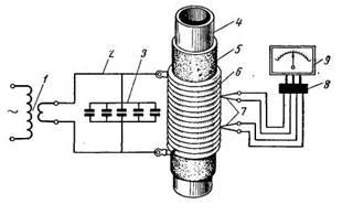
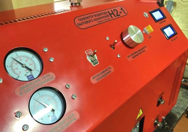 Domestic hydrogen generator
The disadvantage of hydrogen welding can be considered its dependence on the availability of a source of electricity necessary to produce hydrogen. The use of hydrogen cylinders is not allowed due to the danger of their transportation and operation.
Atomic hydrogen method
One type of welding that uses hydrogen is atomic hydrogen welding. Its process is based on the phenomenon of dissociation (decay) of molecular hydrogen into atoms.
To decay, a hydrogen molecule must receive a significant amount of thermal energy. The atomic state of hydrogen is so unstable that it lasts only a fraction of a second. And then there is the reduction of hydrogen from atomic to molecular.
During the reduction, a large amount of heat is released, which is used in atomic hydrogen welding to heat up and melt the welded metal parts.
In practice, the whole process is implemented using electric welding with two non-consumable electrodes. A conventional welding machine can be used to obtain the required current to start the arc. But the holder or burner has an unusual design.
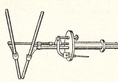
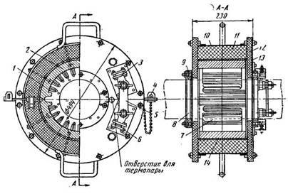
Electrodes and burner
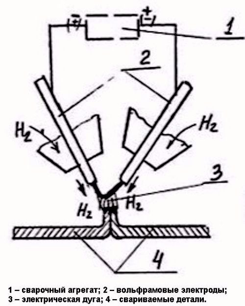
Electrodes with a burner, into which hydrogen is supplied, are located at an angle to each other. The arc is initiated between these two electrodes. Hydrogen, or a nitrogen-hydrogen mixture, supplied to the arc zone, under the influence of high temperature, passes into the state of atomic hydrogen.
Further, when returning to its molecular form, hydrogen gives off heat, creating a temperature that, together with the temperature of the arc, can reach 3600 °C.
Since dissociation occurs with the absorption of heat (hydrogen has a cooling effect), the voltage to start the arc must be quite high - about 250-300 V. Later, the voltage can be lowered to 60-120 V, and the arc can burn perfectly.
The intensity of combustion will depend on the distance between the electrodes and the amount of hydrogen supplied to the welding zone.
Arc burning
 The arc is ignited by briefly shorting the electrodes to each other or on a graphite plate when the electrodes are blown with gas. After ignition of the arc, the distance to the parts to be welded is maintained within 5-10 mm.
If the arc does not touch the metal being welded, it burns evenly and steadily. They call her calm. At small distances to the workpiece, when the arc flame almost touches the workpiece, a strong sharp sound is produced. Such an arc is called ringing.
Welding technology is similar to conventional gas technology.
Welding using the atomic hydrogen method was invented and investigated in 1925 by the American scientist Langmuir. In the process of research, instead of an arc, the heat from the combustion of a tungsten filament was used, through which hydrogen was passed.
Technology
The essence of such a phenomenon as welding under water is explained by the fact that when the arc burns, a gas is released that forms a bubble. Enveloping the electrode and the parts to be welded, the gas releases space for the arc to burn.
As a result, all the heat released by it is spent on heating and melting the metal, which actively resists this, being constantly cooled by the surrounding water.
Its temperature in some cases can reach negative values if the water is saturated with a sufficient amount of salts.
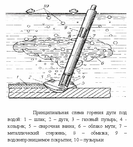
The gas released during the burning of the arc is partly a product of the combustion of metals. Some of its share (hydrogen and oxygen) is formed during the decomposition of water under the influence of electric current and high temperature.
Gas bubbles constantly tend upwards, having less weight and density than water, and a new portion of gas is constantly formed in the welding zone.
Seam shape
Due to the gas floating up in the chaotic movement, as well as due to the combustion products in it (soot, smoke), visibility in the welding zone is very difficult.
This circumstance determines the design features of the seams when welding under water. They are produced in the form of tees, that is, when the parts to be joined are located relative to each other at an angle close to a right one. If the parts to be joined must be located in the same plane, then they are welded not end-to-end, but overlapped.

These types of seams make it possible to work with an electrode under water even in the absence of sufficient visibility, focusing on the edge of the parts to be joined, as if “by touch”.
Voltage and current
The voltage at which welding is carried out under water must be high enough to ensure stable arc burning. As a rule, it varies between 30-35 V.
To supply such a voltage to depth, welding machines are required that can “give out” a voltage of 80-120 V and a weld current of 180-220 A. Underwater welding can be done with both direct and alternating current, but the best results are obtained using direct current.
With an increase in the depth at which welding work is carried out, the intensity of the arc burning, as well as the quality of the resulting welds, does not change. It is only necessary to increase the voltage for stable combustion. Therefore, the possibilities of welding under water are technically unlimited. The depth limit is set only by the capabilities of the human body of the welder and the stability of the equipment for underwater use.
High pressure pipe welding features.
When choosing the type of welding, it is necessary to take into account both the material from which the pipes are made and their diameter.
Welding of the high-pressure pipeline is carried out by gas or electric arc welding. In this case, gas welding can only be used if the diameter of the pipeline pipes is in the range from 6 to 25 mm. For larger pipes, arc welding should be used. With pipe diameters from 25 to 100 mm, manual electric arc welding is used, but if the pipe diameter exceeds 100 mm, then there is a need for semi-automatic or automatic submerged arc welding, while welding the root of the seam in any case is done manually. It should also be borne in mind that in cases where the diameter of the pipes does not exceed 40 mm, as a rule, a conventional weld is used and a V-shaped groove is made. But when welding pipes with a diameter of more than 60 mm, backing rings are most often used.
And another feature of welding work carried out with high-pressure pipes is that it is necessary to perform several layers of the weld - the number of layers depends on the type of pipeline and on the characteristics of the metal and can be from 4 to 10 pieces.
Control of welded joints. Correction of defects in a welded joint
During additional production at the place of operation, installation, repair, reconstruction of pressure equipment, a quality control system for welded joints should be used to guarantee the detection of unacceptable defects, high quality and reliability of operation of this equipment and its elements.
Quality control of welded joints must be carried out in the manner prescribed by the design and process documentation.
All welded joints are subject to visual inspection and measurements in order to identify the following defects:
a) cracks of all types and directions;
b) fistulas and porosity of the outer surface of the weld;
c) undercuts;
d) influxes, burns, unmelted craters;
e) deviations in geometric dimensions and relative position of the welded elements;
f) displacement and joint removal of the edges of the elements to be welded in excess of the prescribed standards;
g) non-compliance of the shape and dimensions of the seam with the requirements of technological documentation;
h) defects on the surface of the base metal and welded joints (dents, delaminations, shells, lack of penetration, pores, inclusions, etc.).
Ultrasonic flaw detection and radiographic control are carried out in order to identify internal defects in welded joints (cracks, lack of penetration, slag inclusions, etc.).
The control method (ultrasonic, radiographic, both methods in combination) is selected based on the possibility of providing the most complete and accurate detection of defects in a particular type of welded joints, taking into account the characteristics of the physical properties of the metal and this method of control.
The scope of control for each specific type of pressure equipment is established based on the requirements of the relevant safety manuals and is indicated in the technological documentation.
Welded joints must not have external or internal defects (damages) that may affect the safety of the equipment. The minimum values of the mechanical characteristics of the welded joints of the equipment must not be lower than the minimum values of the mechanical characteristics of the materials to be joined.
The items of equipment assembled together must ensure the safety of the equipment and be suitable for its purpose. All permanent or welded joints of equipment elements must be available for non-destructive testing.
Installation quality control (pre-production) must be confirmed by a certificate of installation quality.
The installation quality certificate must be drawn up by the organization that performed the installation, signed by the head of this organization, as well as the head of the organization - the owner of the mounted pressure equipment and sealed.
An organization that poorly performed installation (additional manufacturing), repair, reconstruction of pressure equipment is liable in accordance with applicable law.
Inadmissible defects found during installation (additional manufacturing), reconstruction, repair, testing must be eliminated with subsequent control of the corrected sections.
The technology for eliminating defects is established by the technological documentation. Deviations from the accepted defect correction technology must be agreed with its developer.
Methods and quality of elimination of defects must ensure the necessary reliability and safety of the equipment.
Removal of defects should be carried out mechanically, ensuring smooth transitions at the sample points. The maximum dimensions and shape of the samples to be brewed are established by the technological documentation.
It is allowed to use thermal cutting (gouging) methods to remove internal defects, followed by mechanical processing of the surface of the sample.
The completeness of defect removal must be checked visually and by non-destructive testing (capillary or magnetic particle flaw detection or etching).
Sampling of detected places of defects without subsequent welding is allowed, provided that the minimum allowable wall thickness of the part is maintained in the place of the maximum sampling depth and confirmed by a strength calculation.
If defects are found during the inspection of the corrected area, then a second correction must be carried out in the same order as the first.
Correction of defects in the same section of the welded joint is allowed to be carried out no more than three times.
In the case of cutting out a defective welded pipe joint and subsequent insertion of a pipe section in the form of welding, two newly made welded joints are not considered corrected.
semi-automatic way
Due to the fact that a large amount of hydrogen is present in the water during welding, the seam is porous. At the same time, increased cooling of the material with water has a negative effect.
The seam turns out to be fragile, unstable in bending. To obtain a satisfactory result, it is necessary to take into account a large margin of safety and reliability when calculating structures.
Welding under water in an argon environment does not give a tangible effect, since it only slightly reduces the hydrogen content in the seam.
A good result is obtained by the use of semi-automatic welding using flux-cored wire. It has a smaller diameter than the electrode.
When welding with a semi-automatic device, it is possible to organize a constant and continuous mechanized wire feed, which, in combination with the use of non-consumable electrodes, will make it possible to obtain uniform seams of great length.
Materials and equipment
Power equipment for underwater welding - transformers, converters - may not differ in any way from those used for conventional welding. The exception is constructions, the work of which is provided for at great depths. Sometimes the cooling system of such devices is changed.
Hoses and cables
Hoses and cables must be carefully selected and checked for integrity. This need is due to both the requirements of electrical safety and the technology of work.
Welding is very often carried out in sea water, the salt content of which is high. Such water is a good conductor of electricity, therefore, if the cables are not sealed, it may leak, which can have a negative effect on the quality of the arc.
suit
Obviously, scuba equipment is necessary to protect the welder. For work at great depths, a suit or spacesuit can be made of metal. Here lies another trick.
In salt water, the arc can ignite at a decent distance from the metal, without even touching it. And since positive conductivity can be established in the water between the part to be welded and the welder's suit, a discharge may occur with a small distance between the electrode and the suit.
Electrodes and wire
Electrodes for underwater welding deserve special attention. They must be made of a material that is not exposed to water. Welding under water is carried out with mild steel electrodes.
The coating is coated with special compounds that prevent its destruction for a long time, creating a waterproof layer on the surface.
Paraffin, wax, celluloid dissolved in acetone can be used as such compositions. The diameter of electrodes for underwater welding is 4-6 millimeters. There are special brands - Sv-08, Sv-08A, Sv-08GA, Sv-08G2.
When welding with a semiautomatic device, the welding wire of the following brands is used - SV-08G2S, PPS-AN1.
Difficult working conditions require proper organization of the workplace, and compliance with all safety measures.The workplace must be chosen in such a way that waves and currents do not interfere with the welder.
There should be no floating loose objects near the work site. Electrodes should only be changed when the power is off.
Compliance with all the rules and technology of underwater welding will allow you to get excellent results when installing and repairing hydraulic structures, ships, and installing underwater equipment.
Processing of a welded seam when connecting high-pressure pipes.
When welding thick-walled pipes that make up a high-pressure pipeline, the metal is exposed to high temperature, which leads to changes in its structure at the site of the weld itself and at a distance of about 1-2 centimeters from it (that is, in the heated zone) . This leads to the fact that the characteristics of the weld are reduced, which means that there is no guarantee that it will withstand the adverse effects of the environment passing through the pipeline and its environment. In order to avoid this, it is necessary to carry out special processing of the weld and the area located near it.
Most often, heat treatment is used for this, the features of which depend on which steel the pipes are made of and on their exact dimensions. If the pipeline is manufactured under production conditions, then special furnaces are used for heat treatment of joints - these can be resistance muffle furnaces, gas burners with rings or induction heaters.
The resistance muffle furnace is used for heat treatment of joints of thick-walled pipes with a diameter of 30 to 320 mm. In this case, the exact thickness of the walls of the pipes does not matter. In such a furnace, the junction is heated to 900 degrees.
Induction heaters process the connection of pipes by heating the junction with an electric current of industrial frequency (at 50 Hz). Such a heater is used to process the connection of pipes with a diameter exceeding 100 mm and a wall thickness of -10 mm. In order to carry out such a heat treatment, the joint itself and the pipe area located next to it are wrapped with an asbestos sheet, on top of which several turns of stranded copper wire are laid, the cross section of which should be at least 100 sq. mm. When winding the wire, it is necessary to ensure that the turns are simultaneously close enough to each other, but do not touch each other - otherwise a short circuit may occur.
As can be seen from the above, the welded connection of pipes and its subsequent processing are tasks designed for craftsmen with extensive experience in such work.
When carrying out welding, it is necessary to take into account all the features of a particular pipeline - from which pipes it is mounted from, and ending with the conditions under which it will be operated. As for the subsequent heat treatment, here it is also necessary to know the nuances of such an operation and comply with all technological requirements - only such an approach as a result will guarantee a high quality connection.
Getting hydrogen
Hydrogen can be obtained by electrolysis of water, more precisely, an alkaline solution of sodium hydroxide (caustic soda, caustic soda, these are all names for the same substance). Hydroxide is added to water to speed up the reaction.
To obtain hydrogen, it is enough to lower two electrodes into the solution and apply direct current to them. During the electrolysis process, oxygen will be released at the positive electrode, hydrogen will be released at the negative. The amount of hydrogen released will be twice as much as the amount of oxygen released.
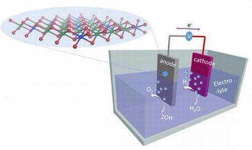
In chemical terms, the reaction looks like this:
2H2O=2H2+O2
It remains technically to separate these two gases and prevent them from mixing, since the result is a mixture with enormous potential energy.Leaving the process uncontrolled is extremely dangerous.
For welding, hydrogen is obtained using special devices - electrolyzers. To power them, electricity with a voltage of 230 V or more is required. Electrolyzers, depending on the design, can operate on three-phase current and on single-phase current.
At home
To use hydrogen welding in everyday life, it is not necessary to buy devices for producing hydrogen. They usually have great performance and power. In addition, such generators are bulky and expensive.
Power and working fluid
Power can be supplied from a car charger or from a homemade rectifier, which can be made with a suitable transformer and a few semiconductor diodes.
Sodium hydroxide solution must be used as the working fluid. It will be a better electrolyte than plain water. As the level of the solution decreases, you just need to add water. The amount of sodium hydroxide will always be constant.
Housing and tubes
As a housing for a hydrogen generator, you can use an ordinary liter jar with a polyethylene lid. In the lid, it is necessary to drill holes for the diameter of the glass tubes.
Tubes will be used to remove the resulting gases. The length of the tubes must be sufficient so that the lower ends are immersed in the solution.

Electrodes must be placed inside the tubes, through which a direct current is supplied. The places where the tubes pass through the cover must be sealed with any silicone sealant.
Hydrogen withdrawal
Hydrogen will be released from the tube containing the negative electrode. It is necessary to provide for the possibility of draining it with a hose. Hydrogen must be removed through a water seal.
It is another half-liter jar of water, in the lid of which two tubes are mounted. One of them, through which hydrogen is supplied from the generator, is immersed in water. The second one removes the hydrogen that has passed through the water from the shutter and delivers it through hoses or elastic tubes to the burner.
A water seal is necessary so that the flame from the burner does not pass into the generator when the hydrogen pressure drops.
Burner
The burner can be made from a needle from a medical syringe. Its thickness should be 0.6-0.8 mm. For the needle holder, you can adapt suitable plastic tubes, parts of ballpoint pens, automatic pencils. It is also necessary to provide oxygen supply to the burner from the generator.
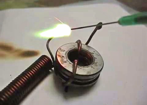
The intensity of the formation of hydrogen and oxygen in the generator will depend on the magnitude of the applied voltage. By experimenting with these parameters, it is possible to achieve a burner flame temperature of 2000-2500 °C.
A self-made apparatus that performs hydrogen welding can be successfully used for cutting or for joining by welding or soldering various small parts made of ferrous and non-ferrous metal. This may be necessary when repairing various household items, car parts, various metal tools.