The process and specifics of installing a storm drain
The rules for the construction of stormwater are similar to those used when installing conventional gutters. However, if the house does not have a drainage piping system, it must be installed.
Construction of the roofing component
When installing a drain, homeowners perform the following actions:
- holes are made in the ceilings of the house for water collectors. After installation and installation of storm water inlets on bitumen, the places of their junction with the storm drain are carefully sealed;
- then, install downpipes and risers;
- elements of the drainage pipeline system are attached with clamps to the cottage or summer cottage;
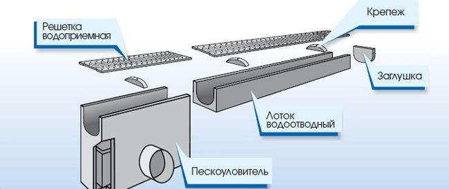
- upon completion of work, trays are installed - when installing a linear-type drain or a water drainage pipe, if the drainage pipeline system is mounted according to a point scheme.
Roof drain
Underground installation
After drawing up a stormwater plan - taking into account the slopes and the specific installation depth of the channels installed in a particular region of the Russian Federation - they make a trench.
If you need to insulate the pipeline with geotextiles and crushed stone, or you need to build a sand cushion, the installation plan for the underground part of the sewer also takes into account the power of the stormwater elements.
Next, perform the following actions:
- before starting installation work, the bottom of the trench is rammed. At the same time, large stones are removed from the trench, the pits from which are subsequently covered with soil;
- a sand cushion is placed at the bottom, the thickness of which is 20 cm;
- the result is a pit in which the collector is installed. A pre-purchased plastic container is used as a collector. However, you can make a collector well with your own hands - just pour the concrete solution into a pre-prepared formwork;
- further, tubes are placed in the grooves, which, with the help of fitting pipeline elements, are connected into 1 system;
- then, inspection wells are placed on straight 10-meter branches of the stormwater;
- sand traps are installed at the junction points of the collectors-water collectors and the pipeline;
- as a result, all elements of the stormwater are connected into 1 circuit. At the same time, the junctions of such elements are carefully sealed.
Before backfilling the trench, they check its performance - pour water into it.
If no weaknesses were found during testing of the trench, then after the test, the pipeline system installed in the trench is buried, filling it with soil. Also in a similar situation, gutters and drainage trays with gratings are placed on the storm drain.
Upon completion of the installation, the owner of the cottage or summer cottage connects the storm drain system to the general sewer.
So, when installing a storm drain on your own in a private household or in a country house, you need to use all the recommendations and rules for installing a drainage system that were given in this article.
Using this information, you can easily troubleshoot problems that arose during the installation of a storm drain.
With the improvement of stormwater in the house and in the adjacent territory, the life of the house is extended, puddles and slush do not form on the roads to the cottage or dacha, and the rotting of plants also stops.
WATCH VIDEO
Each owner of a country house can independently install storm sewers - without seeking help from professional builders. In such a situation, you just need to delve into the essence of the matter - and everything will work out.
Horizontal sand traps with circular movement of water
Horizontal sand traps with circular movement of water are used to remove sand particles larger than 0.2-0.25 mm; they are recommended for station capacity up to 100 thousand m3/day. As a rule, it is planned to install 2-4 sand traps with common water distribution chambers.
The advantage of this type of sand trap is that there are no devices for collecting sand, since the latter settles and accumulates in the conical part of the sand trap. Sand removal is carried out at least once every two days by airlift or hydraulic elevator.
Speeds of 0.15-0.30 m/s are supported in the annular trays of sand traps; the duration of stay of water in the tray is not less than 30 s. A constant water speed with fluctuations in its flow rates is ensured by installing a regulating weir with a wide threshold without a bottom protrusion or a proportional weir in the collection channel behind the sand traps.
The scheme of the sand trap is shown in fig. 3.1.
When designing, the maximum and minimum hourly water consumption and the reduced number of inhabitants are known.
When calculating, the number of sand traps and the minimum diameter of sand particles retained by the sand trap are specified. The calculation procedure is given in table. 3.1.
Rice. 3.1. Horizontal sand trap with circular movement of water: 1 - hydraulic elevator; 2 - shield gate; 3 - switching chamber; 4 - inlet tray; 5 - outlet tray; 6 - slurry pipeline; 7 - working water pipeline; 8 - device for collecting oil; 9 - oil pipeline; 10 - semi-submerged shield; 11 - distribution chamber
Table 3.1
The procedure for calculating horizontal sand traps with a circular movement of water
|
Estimated value and dimension |
Formula or value |
|
Maximum productivity of one sand trap, m3/h |
|
|
Maximum hourly wastewater consumption, m3/h |
- according to the original data |
|
Number of sand traps, pcs. |
= 2 accepted |
|
Estimated value and dimension |
Formula or value |
|
Sand trap diameter, m |
Ds - it is recommended to take according to the table. 3.1.1 depending on qs and the minimum diameter of sand particles retained by the sand trap dp, mm Table 3.1.1 Approximate capacity of sand traps qs with circular movement of water, m3/h Ds, m 0,3 0,5 0,8 1 1,2 1,5 2 With dp = 0.2 mm 4 64 102 145 184 212 250 302 5 100 160 227 228 331 390 473 6 144 230 327 414 477 562 680 With dp = 0.25 mm 4 174 267 371 455 513 584 674 5 272 421 580 712 801 913 1053 6 391 607 835 1025 1153 1315 1517 Notes. 1. The table is compiled for the speed V = 0.3 m/s. 2. Intermediate values are obtained by interpolation |
|
Sand trough settling width, m |
Bs = Hs |
|
Coefficient |
taken according to the table. 3.1.1 |
|
Working water depth, m |
|
|
The area of the living section of the tray, m2 |
|
|
Speed of water movement in the tray, m/s |
Vs = 0.15-0.30; usually taken Vs = 0.3 m/s |
|
Tray length along its axis, m |
Ls = D1 30Vs |
|
Tray diameter along its axis, m |
D1 = Ds - Bs |
|
Retaining capacity of the sand trap, s/mm |
|
|
Hydraulic fineness, mm/s |
U0 = 18.7 mm/s at dp = 0.20 mm U0 = 24.2 mm/s at dp = 0.25 mm |
|
Coefficient |
Ks = 1.7 at dp = 0.20 mm Ks = 1.3 at dp = 0.25 mm |
|
Full height of the tray, m |
|
|
Estimated value and dimension |
Formula or value |
|
Height of the triangular part of the tray, m |
|
|
Tray wall inclination angle, degrees |
= 5060 accepted |
|
Height of the rectangular underwater part of the flume, m |
|
|
Height from water level to side, m |
0.3 accepted |
|
Height of the conical part of the sand trap, m |
|
|
Bottom base diameter, m |
d = 0.40.6 accepted |
|
Full height of sand trap, m |
|
|
Working height of the conical part, m |
|
|
Working volume of the conical part, m3 |
|
|
The diameter of the conical part according to the maximum allowable sand level, m |
|
|
The amount of sand accumulated between cleanings, m3 |
|
|
The given number of inhabitants, pers. |
Npr1 - according to the initial data |
Preliminary calculations and design
Building a storm drain without calculations is a waste of money.
After all, if the installed simple storm system does not work well, then you do not need to install it at all. At the same time, a lot of money needs to be spent on installing a storm drain that is too powerful.
Information required for calculations
When designing a storm drain, the following data are used:
- the average amount of precipitation recorded by meteorologists in a particular area. Such information can be found in SNiP 2.04.03–85;
- meteorological information about the frequency of rainfall and snow thickness. Such data is also used during the installation of a storm drain for the removal of melt water;
- data on the area of the drain - the area of \u200b\u200bthe roof. In such a situation, not the full value is taken into account, but the value of the projection of the area in the plane.
During the construction of a linear storm system, the area of \u200b\u200bthe drain is equal to the sum of the areas of all drain objects;
The principle of operation of the sewer in the context
information about the physical characteristics of the soils that make up the suburban area.
Also, when making calculations, pay attention to the presence and location of underground communication drainage systems already erected on the site.
Calculation of the volume of drains
The volume of drained water is calculated according to the following formula:
The correction factor values used in this formula are used at the following sites:
- 0.4 - on sites that are covered with rubble;
- 0.85 - on a concrete platform;
- 0.95 - on asphalt;
- 1.0 - on the roof.
After determining the volume values, according to SNiP, the diameter of the pipeline drainage system is calculated.
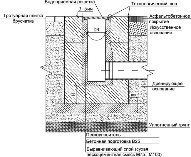
Determining the installation depth of channels
The installation of trays or pipeline channels is done at the same depth at which they are installed in a particular region.
Owners of dachas and private households will find out specific depth values from a construction company or from a neighbor who has already installed a storm drain on his site.
In the central regions of the Russian Federation, storm water is placed at a depth of 0.3 m, if the diameter of the tray is 50 cm as a maximum. Reinforced concrete, metal or plastic gutters and pipes with large dimensions are installed at a depth of 0.7 m.
Due to the high cost of excavation, many owners of country houses do not make strong depressions in the ground. In addition, when arranging a storm drain with your own hands, there is no need to dig it too deep into the ground.
According to GOSTs, collectors and manholes are set at the level of seasonal freezing, and not lower. Also, these stormwater elements can be installed above a similar level - while the collectors and manholes are insulated with geotextiles and gravel, which protects the stormwater from freezing.
Due to the small recess, the complexity of installation is significantly reduced.
In such a situation, storm channels are installed at a specific angle to the drainage and treatment devices of the drainage system.
The device and location of pipes for wastewater
Accordingly, the level of installation of the place of entry into the collector well is below the installation level of the water collector or pipe, which departs from the storm water inlet. When calculating the depth of their installation, they draw up an installation plan in advance and, taking into account the slopes of the drain channels, make all the necessary calculations.
Standards and norms of slopes
According to GOST, tubes with a diameter of 150 mm are set at an angle of 0.008 (the slope is measured in mm / m). Tubes that have a diameter of 200 mm are placed at an angle of 0.007.
Depending on the characteristics of the territory where the storm drain is laid, the installers slightly change the values of the pipe slopes.
A slope equal to 0.02 is made at the junction of the drain channels and the water collector, because in such a place the speed of the drain increases.
Before the sand trap, water flows more slowly than in other areas of the stormwater runoff. In such a situation, suspended particles settle. In this regard, the angle of inclination in this place is made the smallest.
Water collectors in storm drains with a ladder with a sand trap (drain funnel) are placed in those places where the pipe slopes intersect with each other.
Sand trap installation
Video - installation of a sand trap
Before proceeding with the installation of sand traps in a storm sewer system, you should familiarize yourself with some important principles that cannot be neglected in the process:
- First of all, you should take care of the presence of a ditch for a sand trap, which is lined with sand with the addition of gravel or crushed stone.
- Accurately determine the place for installation, which should be in the gap between the gutters and the drain that transports water to the central receiver.
- Care should be taken to ensure that the top of the cleaner is protected by a grid with lockable joints. For devices made of concrete, gratings of the same material are usually used.Cast iron lattice structures are used for concrete fixtures.
- The last nuance will be to provide enough space for periodic cleaning of the device from accumulated debris and sand. Regular cleaning of this device is very important, because if the sewer system is heavily polluted, not only the work stops, but the destruction of buildings and roads begins due to the fact that water begins to wash them away.
Considering the difference in the overall dimensions of the devices relative to the place of application of the sand trap, it is better to consider the installation using the example of a private house or plot. The correct installation process can be described by the following steps, the material of the device is plastic:
- To prevent the storm sewer grit trap from floating up, care should be taken to lay a concrete slab that secures the grit trap with straps. The dimensions of such a plate should not be smaller than the size of the device, even a little more, and it should weigh more than a sand trap with water. It is possible to use metal plates in this design.
- The calculation of a concrete slab is based on the fact that its specific gravity exceeds 2.5 times the mass of water. If the sand trap has a volume of 2 m3, then the mass of the slab should exceed 800 kg, taking into account that its thickness is 15 cm. Calculations for other situations are carried out in a similar way.
- In order to attach the belts to the slab, it is necessary to build locking joints, which must be attached to the holes prepared in advance. You can attach locks both with the help of anchors and with the use of welding equipment.
- In the case of installing a sand trap at a high level due to the fact that groundwater is close enough, then installation is carried out, excluding weighting agents.
- If the device is installed where a load on the soil layer of a sufficiently large force is expected, then the slab must also be laid at the top of the structure.
- In the outer part of the pit, the sand trap is fastened with belts, before that, up to 40 cm of sand fraction or crushed stone is poured to the bottom and rammed.
- After that, the device itself is installed for cleaning waste water from sand, which must be filled 1/3 with water.
- The next step is to fasten the device with a belt structure and fill it with sand and soil up to 2/3 of the level of the sand trap. Compacting the backfill is carried out every 30 cm.
- If the installation of cleaning equipment was carried out without a weight plate, then it is possible to make the backfill a single layer.
- The last step in installing a storm sewer grit trap will be to connect to the entire system, and then continue to backfill until it is all the way to the top. It should also be carefully rammed.
Principle of operation
The functioning of sand traps is based on the use of gravity
When calculating the characteristics of a structure, it is taken into account that sand and other heavy particles should precipitate in them, but impurities of organic origin should not settle. For urban wastewater treatment plants, sand traps are built from reinforced concrete elements.
Aerated sand traps are structures with translational-rotational movement of fluid. They are constructed in the form of elongated tanks. The rotational movement of effluents in these sand traps is created by aeration of the effluents that are in it. In addition, horizontal and vertical sand traps are designed (designing the receiving unit).
Due to the movement of water, each particle in the drains is influenced not only by gravitational, but also by centrifugal forces. As a result of this, an intensive process of separation of sand from water and organic particles takes place, which, due to rotation, remain in suspension.
The amount of sand that falls in aerated sand traps depends on many factors:
- the length of the sewer network;
- slopes in pipeline sections;
- the sewerage system used;
- composition of effluents;
- network operating conditions, etc.
For the city sewer network, the following volume of sediment in sand traps per person per day is accepted (with its humidity of about 60% and density of 1500 kg / m3):
- with a common alloy system - 0.04 l;
- with separate - 0.02 l.
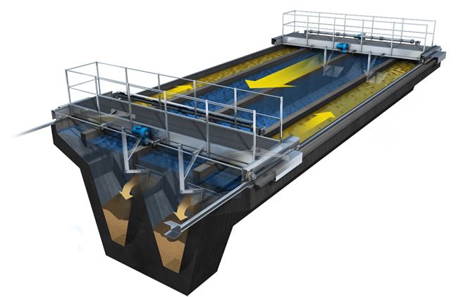
Fig 02 - Sand trap
Characteristics and features
Along the wall of the aerated sand trap (45–60 cm from the bottom of the tank), aerators are tripled, under which trays are laid to collect sediment. For efficient operation, the bottom of the sand trap is arranged with a slope of 0.2–0.4 to collect sand. When calculating the sand trap, the rotational speed along the perimeter of the section of the structure is 0.25–0.3 m/s and the translational speed is 0.08–0.12 m/s. The residence time of wastewater in an aerated sand trap is 2–3 minutes.
To maintain the required rotational speed, 3–5 m3 of air is supplied to the sand trap tank per 1 m2 of the structure area for 1 hour. The rotation is maintained at a constant level without reference to the volume of incoming effluents. Subject to all the necessary conditions at the outlet of the aerated sand traps, a sediment with a minimum amount of organic impurities is obtained. The resulting sediment contains up to 95% sand, which does not rot during long-term storage.
Aerators that are used in sand traps are made of plastic pipelines with holes up to 5 mm. Removal of sand from the surface of the tray is carried out by a flush pipeline. The sediment is washed off without stopping the facility. The effluents cleared of sand are fed into sedimentation tanks.
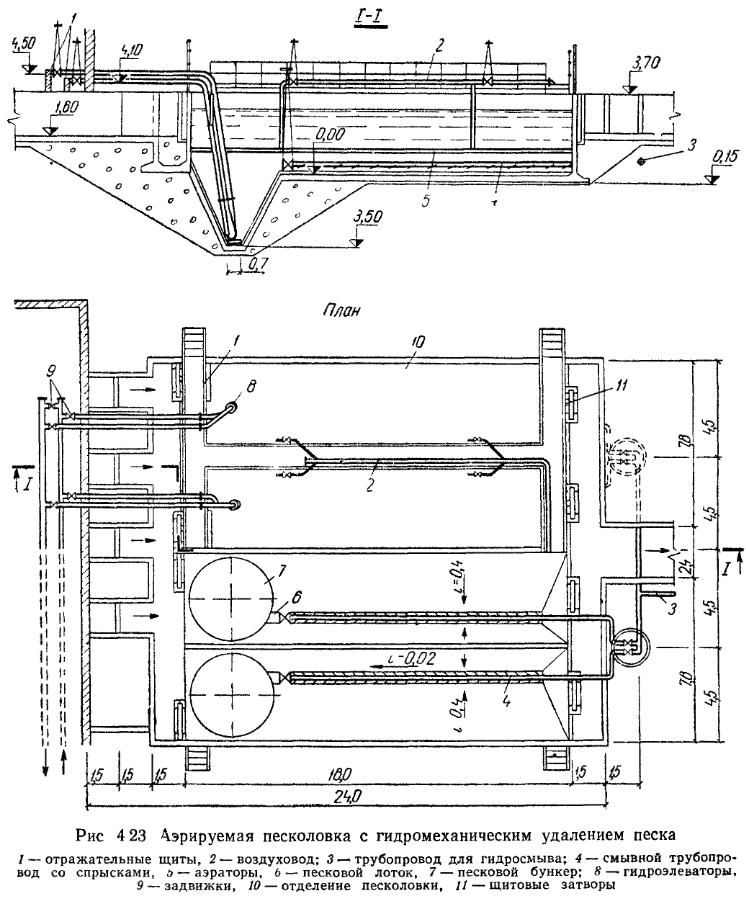
Fig 03 - Scheme of aerated sand trap
In addition to aerated, other types of sand traps are used at city sewage treatment plants:
- horizontal (more than 10,000 m3/day) - elongated rectangular tanks with rectilinear movement;
- vertical - with the movement of drains from the bottom up (in modern conditions they are rarely used);
- tangential, which are a structure with a rotational movement of wastewater (up to 50,000 m3 / day).
The device of sand traps is mandatory as part of structures with a volume of treated wastewater above 100 m3 / day.
| We work throughout Russia | Contacts. Tel/fax + 7(812) 627-93-38; info@dc-region.ru |
- Terms of use
- Personal data processing policy
Description and principle of operation of sand traps
Sand traps are used to retain sand and other impurities from wastewater with a particle size of more than 0.15-0.25 mm at wastewater flow rates of more than 100 m3 / day. The number of compartments of sand traps is taken at least two, while both are working. Depending on the direction of the main flow of wastewater, sand traps are divided into vertical and horizontal, which, in turn, are divided into simple and aerated. The type of sand trap must be selected taking into account its throughput, the composition of wastewater and local construction conditions.
Horizontal sand traps with a circular movement of wastewater are designed to remove sand from wastewater that has a neutral or slightly alkaline reaction. Waste water is brought to sand traps and drained from them by trays. To turn off the sand traps from work, shutters are installed on the supply trays in the distribution chamber. The sediment from the sand traps is removed by hydraulic elevators. The supply of the working fluid to the hydraulic elevators and the removal of the pulp are carried out by independent pressure pipelines, through a switching chamber equipped with valves.
Horizontal sand traps with rectilinear flow of wastewater and a capacity of 70-280 thousand m3/day are operated at a number of sewer aeration stations. Sand traps work effectively when the average velocities are equalized along their length. This is achieved by using single flat gratings at the inlet, made of wooden rods 15 cm wide with 6 cm gaps. In sand traps with gratings of this design, the water load is increased by increasing the flow rate while maintaining the efficiency of sand retention.
Aerated sand traps are used to isolate mineral particles contained in wastewater with a hydraulic particle size of 13-18 mm/s.
The supply of sewage to the sand traps and its removal are carried out by open trays. For the aeration system, air is used from the pump and air blower station. The sludge is washed into the sand trap hopper by a hydromechanical system, including a longitudinal tray and pipelines with showers, the sludge is removed from the hopper using a hydraulic elevator. Aerated sand traps are made in the form of horizontal tanks. Aerators are installed along one of the walls at a distance of 45-60 cm from the bottom along the entire length of the sand trap, and a sand chute is arranged under them. In cross section, the bottom is given a slope
i = 0.2-0.4 to the central tray for gravity discharge of the sand mass into it.
Vertical sand traps consist of receiving and settling compartments and a sedimentary part. The sand trap may be round or rectangular in plan and must consist of two sections.
With a throughput capacity of mechanical treatment facilities of more than 100 m3 / day of wastewater, a vertical tangential type sand trap or a sand trap with a downward-upward movement of the liquid is used.
The operation of such sand traps is based on a qualitatively new principle. Waste water enters the sand trap tangentially, resulting in its rotational movement. The sand contained in the waste water is pressed against the walls by centrifugal force and separated from the water as a result of the resulting downward flow.
The removal of water from the sand trap by the central telescopic pipe further intensifies the separation of sand by creating a water funnel around the inlet of the pipe. Washing sand from organic impurities is carried out in the process of its removal in a screw sand washing machine.
Principle of operation
Of course, it is easiest to choose and purchase a ready-made sandblasting unit, but not everyone can afford it.
A way out of the situation may be to rent the device, but in this case, its service life will be limited, and in the event of any breakdown, you will have to pay for repairs.
Anyone who is familiar with the basics of mechanics and regularly needs a sandblasting device designed to process various types of surfaces, but does not have extra money, can easily assemble it with his own hands.
Such an automatic home-made sandblaster, subject to the assembly technology, will in no way be inferior in its functionality to the device assembled at the factory.
In this case, you will have to make some efforts and acquire all the necessary material and tools that will be required in the process.
First of all, it is necessary to study well the principle of operation of the sandblasting machine and understand the concept of its operation.
The compressor, which is part of the operation scheme of the apparatus, supplies air under high pressure, which, having captured the abrasive material, with the help of a nozzle, enters the surface that requires processing.
For a homemade device, it is better to use a factory compressor that can create the necessary pressure. In some cases, you can create the necessary pressure in the system using a gas cylinder.
In addition to the air source, the general circuit of the apparatus must necessarily include supply hoses of a given diameter, cables, and a main power source.
The operation of a sandblasting unit is also impossible without a special nozzle, which has some design features.
It should also be noted that the nozzle material should be either tungsten carbide or boron. It is strictly forbidden to use nozzles made of cast iron or ceramics, as they will fail very quickly.
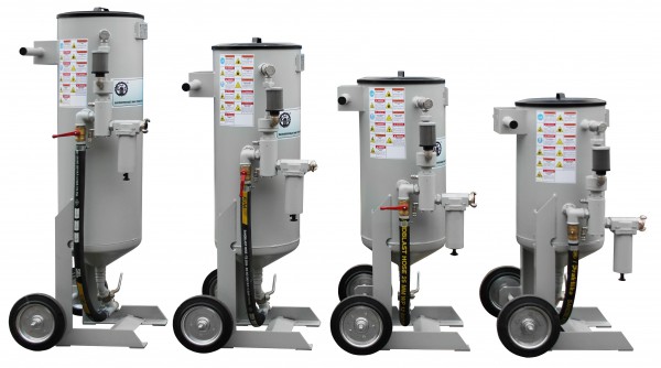
The photo below shows factory-made sandblasters and nozzles that are suitable for processing various types of surfaces.
Advantages and disadvantages
Buying or renting a sandblasting device requires certain financial costs, and in this case, many craftsmen try to make a unit for processing various surfaces on their own.
If you follow the assembly sequence and use high-quality components, then the device will in no way be inferior to professional equipment in terms of its operating parameters.
In addition, it can be additionally equipped with air recirculation, which will only increase the capabilities of a home-made device.
In general, devices with air recirculation work several times more efficiently and provide better processing.
In the photo below, you can see a variant of a home-made device of this type with air recirculation.

If you have minimal knowledge in mechanics, the process of assembling the device will not take much time and will save you on the purchase of a sandblasting unit assembled at the factory.
A truly high-quality result can only be achieved if only high-quality components are used when assembling an apparatus with recirculation.
The video below will help with self-assembly of this unit.
When assembling a sandblasting unit on your own, you should not rush, as such an apparatus may subsequently work incorrectly and quickly fail.
Particular attention should be paid to the compressor. For this device, use the compressor that is able to create the required air pressure.
Video:
The same fully applies to the nozzle, which must be of a certain size, and besides, made only of tungsten materials.
According to some operating parameters, a self-assembled sandblasting device may be inferior to factory units, but this will not affect the quality of processing much.
If this equipment is required for one-time work, then in this case, the way out may be to rent the unit at any specialized center.
If financial possibilities allow and a machine of this type is used regularly, as a result of which it is necessary, then it is best to choose a factory sandblaster, similar to the one shown in the photo at the beginning of our article.
Video: