Classification of toilet bowls depending on the drain
In the picture above, you can clearly see what kind of drain toilets have.
The vertical outlet toilet is attached with special parts directly to the floor surface. The most widespread direct outlet of the toilet was in the countries of the Northern Hemisphere. This is very simple to explain: most of the sewer line is located under the floors, and communications are not connected with internal partitions and walls. In the United States of America, almost all communication networks (water supply, electricity supply) are laid according to this principle.
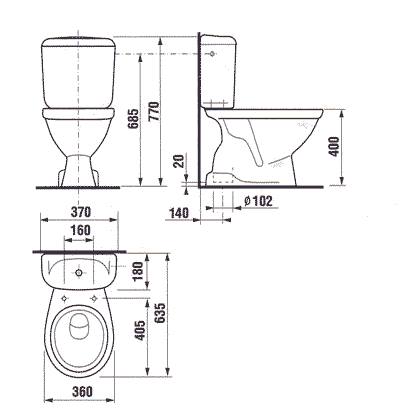
Toilet bowls with a horizontal drain, which is parallel to the floor surface, are more common in European countries and in the CIS. During the 1970s and 80s, houses were built according to the principle that it was possible to install a toilet bowl in them, which has a horizontal or oblique (corner) drain.
And the third type of structures - having an oblique (angular) drain, which is at an angle of 45 ° with respect to the floor surface.
More about installing a toilet with a corrugated pipe
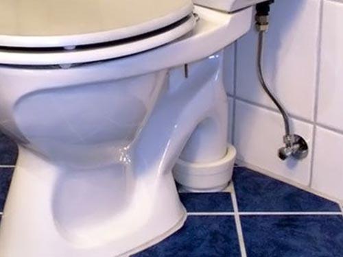
A direct outlet toilet can be installed using a corrugated pipe. This element is used when it is not possible to use other materials. To do this, the pipe is installed in the sewer hole, and the joints should be treated with silicone
The device is connected to the other end of the pipe, and it is important to make sure that the connection is as reliable as possible. To do this, draw water into the tank and drain it
If there are no leaks, then you did everything right.
It is important to determine the drilling location for installing fasteners in the form of dowels. To do this, the toilet is installed in the intended place so that it is possible to mark the holes with a pencil
When a toilet is installed, with a direct outlet to the floor, it is necessary in the next step to remove the device from the attachment point in order to drill holes. Dowels are installed in them, and the toilet bowl is mounted to the sewerage system.
Inside, the pipe is coated with sealant, and before further action, you should make sure that the connection is secure. If the water flows freely, then all fasteners can be mounted
It is important to check the stability of the device, if it sways, then a cement-sand mortar screed is made under the toilet. Toilets-compacts, which have a direct outlet, must be sealed in those places where the device was docked with the tile
In this case, you can use silicone or sealant. On this we can assume that the installation with the help of corrugations is completed.
WARNING WHEN DISCONNECTING THE SHOCK ABSORBER INSTALLED ON THE UPVS 80S AND UPVS 80SN UNITS, BE CAREFUL AS THE SPRINGS IN THE SHOCK ABSORBER ARE IN A COMPRESSED STATE AND MAY CAUSE INJURY.
1 - riser I, 2 - riser II, 3 - manual pump, 4. - elbow, 5 - quick coupling 3P-00, 6 - quick coupling 3-80-0-00, 7 - ball valve, 8 - USN type installation (not included in the delivery set), 9 - sleeve 25x35 -1.6 (8 m), 10 - sleeve 25x35
-1.6 (1.5 m).
Figure A.1 - Portable installation for the top discharge of oil and oil products from railway tank cars UPVS - 80. Mounting dimensions.
814.00.00.00 RE 1 - riser, 2 - riser, 3 - manual pump, 4 - ball valve, 5 - VK80SSE connection, 6 - MK80SSE connection, 7 - elbow, 8 - riser, 9 - pipeline, 10 - pipeline, 11 - drain manifold valve. (not included).
Figure A.2 - Portable installation for the top discharge of oil, oil products and corrosive liquids from railway tank cars UPVS-80N.
Connecting dimensions.
814.00.00.00 RE 1 - riser, 2 - tip, 3 - pipe, 4 - quick coupling, 5 - hand pump, 6 - drain manifold valve (not included in the delivery), 7 - housing.
Figure A.3 - Installation for the top discharge of oil and oil products from railway tank cars UPVS - 80S.
Connecting dimensions.
814.00.00.00 RE 1 - riser, 2 - tip, 3 - pipe, 4 - quick coupling, 5 - housing, 6 - drain manifold valve (not included in the delivery set), 7 - vacuum pump (not included in the delivery set).
Figure A.4 - Installation for the top discharge of oil and oil products from railway tank cars UPVS - 80S without a pump.
Connecting dimensions.
814.00.00.00 RE +5.500 +5.360 4 +4.600 +0.655 0.000 255* 200* 22* 4. 7 195* 140*
— 205 17 4.
170 ± 0.3 1 - riser, 2 - tip, 3 - pipe, 4 - quick coupling, 5 - housing, 6 - drain manifold valve (not included in the delivery set), 7 - vacuum pump (not included in the delivery set) .
Figure A.5 - Installation for the top discharge of oil, oil products and corrosive liquids from railway tank cars UPVS - 80SN.
814.00.00.00 OM Figure A.6 - Installation for the top discharge of oil, oil products and corrosive liquids from railway tank cars UPVS - 80S and UPVS - 80SN.
Service zone.
814.00.00.00 RE
Figure A.8 - Manual pump for portable units for top discharge of oil products from railway tank cars UPVS - 80, UPVS - 80S and UPVS - 80N 814.00.00.00 RE - body, 6. - hinge, 7 - knee. eight
- hinge; 9- knee; 10 - quick-detachable connection.
Figure A.9 - Riser for UPVS - 80S and UPVS - 80SN units.
1 - casing; 2 - spring; 3 - hairpin M20; 4 - hairpin M20; 5 - hairpin M16; 6 - nut M16.
Figure A.10 - Shock absorber. Dimensions.
814.00.00.00 RE 1 – outer clip, 2 – inner clip, 3 – separator; 4 - ring; 5 - cuff; 6 - ball; 7- oiler; 8 - cuff.
Figure A.11 - Ball joint. Dimensions.
1 - outer clip, 2 - inner clip, 3 - ring; 4 - ring; 5 - cuff; 6 - roller; 7- oiler; 8 - cuff.
Figure A.12 - Roller joint. Dimensions.
Russia, 303 858 Livny, Oryol region, st. Mira, 40
Installation of sinks
Each type of shell has its own mounting method; most often, plumbing installers install sinks on brackets. With this installation method, special brackets are required that are attached to the wall with screws, the main thing in this matter is to choose a drill of a suitable diameter.
Sometimes there are no holes for fastening in the mounting “ears” of the sink, therefore, before fixing the sink with threaded brackets, holes should be drilled in them and, after installing the brackets in their place, fix them with a nut and a wrench.
Drain assembled (whole system)
After installing the sink, the faucet and sink drain are mounted, the system of which together includes:
- Siphon;
- corrugated tubes;
- Hydraulic shutter;
- And additional items.
The drain hole of the sink should be blocked by a drain grate, on top of which a rubber seal is installed, which is fixed by a nut located under the sink.
A siphon is attached to the tube draining from the drain hole with a lock nut, which fixes it in a fixed position, and a sealing wedge-shaped ring is inserted between them. Next, a drain pipe is attached to the siphon, connecting it to the sewer.
The socket of the sewer pipe is equipped with a special rubber cuff, which will help contain the smell from the sewer so that it cannot spread throughout the room. The cuff should tightly cover the flexible outlet tube, so its inner diameter should be slightly smaller than the outer diameter of the tube.
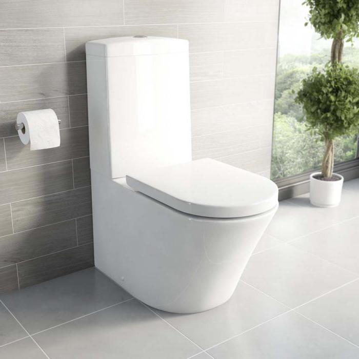
Features of the toilet with direct outlet to the floor
Vertical drain has its own distinctive features. Before choosing the right edition, you need to familiarize yourself with them. This will help determine the type of drain.
 A toilet with a vertical release of human waste is installed using a special adapter directly into the sewer hole
Key Features of Direct Release:
- This type has a hidden pipe.At the same time, the siphon, which protects the premises from unpleasant odors, is located inside the body of the product. This allows you to install the drain in any corner of the room. In addition, this is a significant space saving.
- You can install the device yourself. All installation steps are quite simple and do not require special skills.
- Pleased with the hygiene of the drain. The required high level guarantees this.
- Rinsing is fast and good. The toilet bowl does not create splashes, and the dirt from the walls of the bowl is perfectly self-cleaning with water.
- Good flushing is ensured by the pulling forces of the siphon.
All features characterize the vertical drain from the best side. For toilets with floor outlet, there is no problem with the constant cleaning of unwanted splashes. A hidden design is especially relevant for small rooms.
Main differences
Among the masters, it is believed that the oblique outlet of the toilet bowl is optimal. It is easier to connect such a compact to the sewerage system, since it is located in relation to the toilet within 0 to 35 degrees. Unfortunately, for a toilet with a vertical outlet, including a horizontal (straight) pipe, a strictly fixed connection point is needed, which will additionally be located in a certain place on the floor.
In addition, the toilet with an oblique outlet has the following distinctive advantages:
A slanted outlet gives less resistance to faeces passing through, so it will be less likely to clog and need to be unclogged. The opinions of experts are unanimous that when installing sewerage systems it is better to purchase a compact with smooth turns (two rotary parts at an angle of 45 degrees) than one knee with an angle of 90 degrees.
Installation of a slanted outlet toilet is much easier due to the lack of a fixed connection point on the floor. But even if, when summing up the sewer, the outlet socket of the toilet is not exactly located - this will not be a hindrance for you.
Popularity
If you take a walk through plumbing stores for the sake of interest, including on the Internet, then pay attention to this feature - for about every ten models with an oblique toilet outlet, you will have two or three versions of toilets with a horizontal outlet and one with a vertical outlet.
5 MANUFACTURER WARRANTY
5.1 Warranty period of operation - 12 months from the date of commissioning of the units, but not more than 18 months from the date of shipment by the manufacturer.
5.2 The manufacturer guarantees the compliance of the installations with the requirements of TU 3689-252-05806720-2007, subject to the conditions and rules of operation, the rules of storage, transportation and installation established in the operation manual.
6 DISPOSAL
At the end of the service life, carry out work on the disposal of the installation:
— clean the installation from the remnants of oil products;
- disassemble it into assembly units and parts, depending on the materials (ferrous and non-ferrous metals, rubber) and dispose of it in accordance with the regulations of the consumer enterprise.
4 INFORMATION ON PRESERVATION, PACKAGING, TRANSPORTATION AND STORAGE
4.1 Preservation information 4.1.1 After the acceptance tests, the internal cavities of the installations must be freed from the test liquid and preserved with industrial oil I-20 GOST 20799-88, and the inlet and outlet openings should be closed with plugs. Before packaging, all external unpainted surfaces must be preserved in accordance with GOST 9.014-78, protection option VZ-1, preservation period - 2 years.
4.2 Packing information 4.2.1 Component parts of the unit are packed in crate type II-1 according to GOST 12082-82 or other container as agreed with the customer and have their own separate packing place.
814.00.00.00 РЭ Packaging excludes the movement of units and parts of the unit inside the container during transportation and protects them from mechanical damage.
4.2.2 Operational documentation is packed in a plastic bag or waterproof paper. Accessories, spare parts and accessories are wrapped in waterproof paper. Operational documentation, components and spare parts are placed inside the package.
4.2.3 The packing list is located along with the operational documentation.
4.3 Information about storage and transportation 4.3.1 Storage conditions for installations in terms of the impact of climatic factors - according to group 4 of GOST 15150-69.
4.3.2 Assigned shelf life is 9 years.
4.3.3 The units must be stored indoors or under a shed. The installation method is in one row.
4.3.4 When storing units in warehouses in the ambient air, there should be no vapors of acids, alkalis and other aggressive impurities.
4.3.5 During long-term storage, it is necessary to check the state of conservation at least once every six months.
4.3.6 The units are transported by all modes of transport, in accordance with the rules for the carriage of goods in force for each specific mode of transport, at an ambient temperature of plus 50 to minus 50 0C and a relative humidity of 80% at a temperature of 20 0C.
4.3.7 Conditions for transportation of the installation in terms of the impact of mechanical factors "L" in accordance with GOST 23170-78.
— THERE ARE VISIBLE LEAKS AND DROPS
2.2 Installation of installations 2.2.1 Safety measures during installation 2.2.1.1 Installation work is allowed for persons with the necessary qualifications who have studied this manual and the safety instructions approved by the head of the consumer enterprise.
2.2.1.2 Installation and operation of the unit must be carried out in compliance with safety rules, production instructions developed taking into account PB 09-540-03 and PB 09-560-03.
2.2.1.3 The installation must be grounded using a grounding clamp. In this case, it is necessary to be guided by the PUE and Instruction VSN-332-74 / MMSS. The connection point of the external earth conductor must be carefully cleaned and protected from corrosion by applying a layer of grease.
Upon completion of the installation, check the resistance value of the grounding device, which should be no more than 10 ohms.
Checking the resistance value should be done 2 times a year.
2.2.2 Inspection procedure and checking the readiness of the product for installation
In doing so, you need to pay attention to: — warning labels;
— warning labels;
- the presence of fasteners /bolts, nuts, washers./;
— state of grounding;
— tightness of plant connections;
- Availability of operational documentation.
2.2.2.2 All fixing bolts must be tightened. The tightening of threaded connections must be uniform.
2.2.3 Rules and order of installation 2.2.3.1 Installation of the installation is carried out according to a standard project agreed with the local fire inspection in compliance with safety requirements.
2.2.3.2 Install the unit with the body on the support, install the studs and evenly tighten the nuts on the studs.
2.2.3.3 The installed unit must be grounded by connecting it to the ground loop in accordance with the regulations on grounding industrial installations and removing static electricity.
2.2.3.4 After installation, check the joints and seals, and in case of product leakage, eliminate the leak by replacing gaskets and seals.
2.3 Preparing the product for use 2.3.1 Safety measures in preparing the product for use 2.3.1.1 When preparing for start-up and operating the units, it is necessary to follow the sequence of operations specified in the technological regulations and equipment operating instructions. Operating personnel should only perform work for which they have been instructed and trained.
814.00.00.00 OM 2.3.1.2 When working in places where the formation of an explosive mixture of gases and vapors with air is possible, a tool made of intrinsically safe material should be used.
2.3.1.3 Explosion-proof lamps shall be used as portable lighting during drain operations or repair work.
2.3.1.4 The execution of technical means of communication during discharge operations or repair work must comply with the class of explosive zones.
2.3.1.5 Open and close manhole covers of tanks, railway and road tanks carefully, preventing them from falling and hitting the manhole neck. 2.3.1.6 Employees performing work at heights, who are in the danger zone of falling from a height or objects falling on them from above, must wear helmets in accordance with GOST 12.4.087-84
2.3.1.6 Employees performing work at heights, who are in the danger zone of falling from a height or objects falling on them from above, must wear helmets in accordance with GOST 12.4.087-84.
2.3.1.7 Heating of frozen or crystallized products in pipelines shall be carried out with hot water or steam.