How a drainage system project is created
It is desirable to develop a drainage system project at the site development stage, since surface and groundwater can have a destructive effect both on green spaces on the site and on structures. This approach will effectively and comprehensively solve the problem of flooding, avoid unnecessary financial and labor costs. But employees of our company can carry out drainage after construction. It will just take longer, and, accordingly, will cost a little more.

The design of drainage systems in our company is regulated by the relevant regulatory documents - SNiP 2.06.15-85 and 2.04.03-85 and is based on modern developments of such organizations as Mosproekt, NII Mosstroy and others in the field of drainage from polyethylene pipes with a filter shell.
Information you need to work on a drainage project:
- Plan of the site with buildings marked on it and indicating the depth of laying the foundations
- Topographic survey of the territory (for complex reliefs or geoplastics that are complex in concept - mandatory, for flat areas with simple relief - not mandatory)
- A landscaping map (denroplan) is required to link the drainage system to the planned landscaping areas
- A road and path plan is needed in any case (for the effective collection and removal of water from paths and solid paving areas)
- Geological and hydrological data of the developed area. This data may not be needed if the building block on which the site is located has already been studied and the soil has the same structure. Those. re-ordering "geology" is not required.
- Communication plan on the territory (existing and planned).
Types of drainage used in drainage projects
Extract from SNiP 2.06. 15-85 (clause 3.23 "Engineering protection of the territory from flooding and flooding"): "When choosing systems of drainage structures, the shape and size of the territory requiring drainage, the nature of the movement of groundwater, the geological structure, filtration properties and capacitive characteristics of aquifers should be taken into account , the area of distribution of aquifers, taking into account the conditions of recharge and discharge of groundwater, the quantitative values of the components of the groundwater balance were determined, a forecast was made for the rise in the level of groundwater and its decrease during the implementation of protective measures.

Drainage systems used today are classified according to many criteria - by objects of landscape architecture, by target orientation, by design, by principle of operation, by materials used, by hydrogeological conditions and soil properties. Here are just a few of them, the most relevant for the drainage of plots for private households.
According to the design of the watercourse, drainage is:
Open (cavitary) - the easiest to implement. Along the perimeter of the site, trenches are dug with a depth of 0.6-0.7 m and a width of 0.5 with a deviation of the walls from the vertical to the outside by 30 °. Open drains are used to collect and redirect melt and rainwater in areas located on slopes.
Zasypny (cavity with filler) - is equipped as follows: the bottom and walls of the trench are lined with geotextile, which acts as an additional filter material and prevents drainage from silting. The geotextile is laid out so that it protrudes 30 centimeters on each side of the ditch. Then half the trench is filled with broken bricks, large gravel, after which material of a finer fraction is poured almost to the top. The filling of the ditch is closed with the edges of the geotextile, soil is poured on top and turf is laid.
Closed (tubular) - differs from backfill in that in a ditch, on a prepared pillow of sand and gravel, drainage pipes are laid under a certain slope. Then a water-bearing layer of sand and gravel is created on top of the pipes. Geotextiles are used, as in the previous case. The scheme of the drainage system of a closed type, as a rule, is made in the form of a "herringbone" (other configurations may be possible). Water from the side channels flows into the central one and is diverted to the place of water discharge.

According to the principle of action, drainage is distinguished:
- systematic (distributed evenly across the site)
- selective (the drainage system is laid selectively, under separate sections of the territory)
- clipped (head) - to intercept and redirect groundwater that comes from the outside (for example, during flooding).
According to soil and hydrogeological conditions:
- horizontal drainage - differs in that the drains are laid horizontally with a calculated slope towards the discharge of water
- vertical drainage - is a system of wells and wells.
By types of objects of landscape architecture:
- double drainage - fits in areas where a high density of planting trees and shrubs is planned, due to which the repair of the system will be difficult in the future
- coastal drainage - carried out in floodplains
- wall drainage - to drain water from the walls and foundation of the building
- reservoir drainage - used in cases where water accumulates under the platform or structure.
Drafting of drainage systems
The design of the system begins with geodetic and hydrological calculations of the site. This work is being done for the purpose of determining the operating conditions, as well as the structure of the drainage system, as well as its key indicators.
The project must contain:
- Schemes and technical drawings of the sewage system and all its components, both on the surface and underground parts
- Installation properties of drainage systems - diameters, dimensions, laying depth and slope of the drainage pipe. SNiP gives norms for these values
- Dimensions of all components that make up the network - wells, connectors, fittings and other details
- Feasibility study of building drainage systems
The project documentation should include the following specifics:
- The geomorphology of this area
- Features of the climate of the territory in which it is located
- Groundwater level marks
- Characteristics and structure of soils
- Distance of water bodies from the construction site
Existing technologies for installing a drainage system
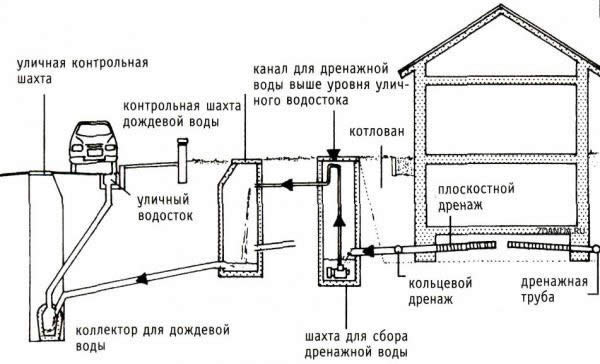
Scheme of closed drainage on the site.
The need for drainage is quite easy to determine. It is needed when the soil on the site consists of clay and various types of loam. After rains, large puddles form on the site. At the same time, the relief of the site can be either flat (there is nowhere for water to drain), or inclined and located at the bottom (water from the top of the site flows into it). In both cases, a drainage system is simply indispensable.
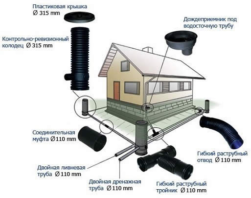
To carry out work on the creation of a drainage system, we need:
- pipes;
- couplings;
- fitting;
- wheelbarrow;
- 2 shovels: shovel and bayonet;
- hacksaw;
- roulette;
- level;
- rail;
- tamper;
- sand;
- crushed stone;
- gravel (fraction 2-4 cm);
- geotextile.
Drainage systems are divided into 3 main types: open, closed and backfill. The simplest is an open system. Her device is as follows. A ditch with a depth of 70 cm and a width of about 50 cm is dug along the perimeter of the site. The slope of the ditch wall should be 30 º. All water drains out of it into a large gutter that serves several sites at once. This method of drainage is very effective during the melting of snow in spring and heavy rains in autumn.
Above the slope, a transverse intercepting ditch should be dug. It collects water flowing from the top of the site.From its 2 ends at an angle, diverting channels go down, connected to a large common gutter.
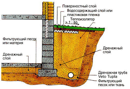
Sectional diagram of the drainage system.
An open drainage method is an acceptable option only for small areas with a uniform topography. If the area is large and, in addition, is characterized by different heights (sometimes with slopes in different directions), then it will be necessary to equip a closed or backfill drainage system.
Both systems are quite similar in execution technology. The only difference is that the closed drainage system provides for the laying of special perforated pipes into the ditches. With backfill technology, broken bricks or large gravel are poured into the ditches, on top of which a layer of finer gravel or soil is laid. Water is filtered through the filler. It leaves in a given direction along the clay outlet.
SNiP Rules for drainage, budgeting and design
The device and design of the drainage of the foundation of buildings should be carried out in accordance with the requirements of SNiP (Building Norms and Rules). Drainage, made in full compliance with all standards, will serve properly for many years and perform the proper functions.
Basic rules for drafting a drainage system.
measure the level of groundwater
calculate the average monthly rainfall
determine the composition of the soil
take into account the location of the nearest natural reservoirs
measure the level of soil freezing
carry out geodetic measurements of the landscape
At the second stage, the drafting of the project itself is carried out, which includes:
a schematic representation of the future drainage system is drawn up
the calculation of the parameters of the depth of the pipes, slope, section is performed, the features of the assembly are taken into account
components corresponding to the standard size are selected (drainage pipes, wells, fittings)
a list is compiled and the amount of necessary additional materials is calculated.
Properly drawn up project documentation will significantly reduce the installation time of the system, save money on building materials and equipment, and ensure reliable operation of the system.
What is the estimate of calculations for the arrangement of the drainage system
When drawing up the estimate, not only the cost of materials and equipment for laying the drainage system is taken into account, but also the cost of dismantling the coating or foundation pavement and the cost of the work itself, as well as restoring the coating and laying new soil for normal plant germination.
The main components of the estimate for the production of work on the installation of a drainage system are the costs of the following types of work:
dismantling of the old coating or blind area of the building
digging a trench for laying the system
backfilling of crushed stone under the pipe system
installation of inspection wells and a storage well
reinforcement of trench sides
flooring of a new coating or blind area
This is how the cost and quantity of the necessary materials are calculated:
paving slabs or asphalt pavement
new fertile soil
The estimated cost of work and materials will depend on the length of the pipeline and the depth of its immersion in the soil.
Rules for the installation of a drainage system
Drainage design is carried out in accordance with the rules and SNiP 2.06.15-85 and SNiP 2.02.01-83. The closed drainage system is mainly laid at a depth of 0.7 to two meters, with the exception of areas with deep freezing of the soil. The width of the drainage system should be in the range from 25 to 40 cm. It is necessary to take into account the slope of the system, as stated in the SNiP:
for clay soils, the slope value is calculated at the rate of 2 cm per linear meter of the pipeline
with sandy soils 3 cm per linear meter
The bottom of the trench is covered with a layer of crushed stone with a fraction of 5 to 15 mm, the thickness of the pillow is at least 15 cm. A pipeline system is laid on the crushed stone pillow, drainage wells are mounted, and soil is sprinkled. During the operation of the system, water passes through the drainage system, collects in a collector, and then drains into the nearest reservoir or ravine. The drain site must be cemented and located at an acute angle to the shore of the reservoir. Foundation drainage is controlled by inspection wells made of reinforced concrete or plastic pipes. The groundwater level will not only not rise, but also fall, which will significantly increase soil fertility if the drainage system is installed and designed in accordance with the rules of SNiP.
All these rules and standards are known to professionals, so if you decide to do the drainage of the foundation or the entire site with your own hands, first read and study all the rules and regulations, and only then proceed to work. In case the learning process seems difficult to you, entrust the drainage device to specialists.
Project Creation Basics
Design is the initial stage in the performance of any work. This directly applies to the creation of a drainage system.
Scheme of wall drainage.
When designing a drainage system, the following factors are taken into account:
- the level of resistance of soil rocks to the process of washing out particles;
- permeability index of individual rocks;
- the presence of tectonic disturbances in the area;
- groundwater composition;
- location of sources feeding groundwater and their intensity.
The drainage plan must comply with the provisions of the current regulations. The main requirements for are:
- the size of the slope from the top point of the pipeline to the catchment facilities is 0.5-0.7%;
- the presence of elements that control the functioning of the system and flush it;
- the bottom of the pipe is located 20 cm below the level of the foundation (if the drainage is close to the house)
If possible, the plan should include the installation of revision wells. They should be installed at pipe bends.
Cn drainage systems
Design of external sewerage, gutters and drainages
6.1.1 The choice of pipes should be made taking into account the composition of the effluents, their temperature, based on hydraulic and strength calculations.
6.1.2 For gravity sewerage, pipes of the sewerage range should be used. The use of pressure pipes must be justified.
6.2.1 For non-pressure sewage, smooth pipes are unified in terms of outer diameters, except for pipes made of glass and basalt plastics, which are made by winding.
According to the ring stiffness of the shell, pipes are divided into classes: non-rigid, semi-rigid and rigid. The class of pipes is given in Appendix A.
6.3.1 On gravity sewer pipelines, both detachable and permanent connections should be provided.
6.3.2 Flare connections sealed with rings of various profiles should be used as detachable ones.
6.3.3 The main types and methods of pipe connections are given in section 3.3.
6.3.4 For sewerage pressure pipelines, one-piece connections should be used predominantly - gluing and welding.
6.3.5 Detachable connections (flanged, etc.) on pressure sewers are usually used to connect pipes to equipment.
6.4.1 The tracing of external sewerage must be carried out taking into account the requirements of SNiP 2.04.03.
6.4.2 Gravity sewer pipelines must be straight only. Changing the diameter of the pipeline and its direction is allowed only in wells.
Pressure sewer systems are performed in accordance with Section 5.
Calculation of gravity pipelines for strength should be carried out according to the method given in Appendix D.
Hydraulic calculation of gravity underground sewer pipelines is carried out according to the formulas given in section 4.5.
6.7.1 The need to compensate for the thermal expansion of pipes in a pressure sewer is established by calculation in accordance with Section 3.7 of this Code of Rules, taking into account the pinching effect of the soil.
When the pipeline is pinched by soil, the elongation of the pipeline decreases. Reduction amount D lmind is determined by the formula
where fT - coefficient of friction of the material on the ground, determined empirically, in the absence of data can be approximately taken equal to 0.4,
g - volumetric weight of the soil, N / m 3,
H — pipeline laying depth, m,
L — pipeline length, m,
E szh is the modulus of elasticity of the material in the direction of deformation, Pa,
s — pipeline wall thickness, m,
Ky — coefficient of soil compaction, taken equal to 1 with a degree of compaction of 0.95 and 0.5 — with an uncontrolled degree of compaction when backfilling a trench.
6.7.2 Compensation for temperature deformations of pipelines in gravity sewers is provided by:
- socket connections, sealed with rings,
- partly in sewer wells by arranging a passage through the walls of the well and stuffing the tray.
6.8.1 For drainage systems, it is allowed to use sewer, drain and water intake wells made of: polymeric materials (PE, PVC, etc.), combined (elements made of polymeric materials in combination with reinforced concrete elements), reinforced concrete and brick. The dimensions of the wells must comply with those specified in SNiP 2.04.03.
6.8.2 Wells made of polymeric materials should be used in conjunction with a reinforced concrete protective slab and traditional metal hatch elements.
6.8.3 The tray part of the wells made of polymeric materials must have ready-made trays made of polymeric materials, as well as protruding branch pipes for connecting the pipeline.
Is wall drainage really necessary around the house Construction nuances
Wall drainage is arranged to drain rain, melt and groundwater (rising during floods) from the foundation. When is its installation necessary, and when can you do without building a drainage system around the house? Features of wall drainage, drafting.
Wall drainage device
Schematically, the drainage system near the foundation can be designated as follows:
- a closed network of perforated pipes around the house, made with a single slope towards the bottom point,
- where the collection well is installed,
- from there, the water flows out of the site,
- inspection and cleaning of the system is carried out through inspection wells installed at every second bend.
Of course, during the construction of the building, the foundation is protected with waterproofing materials. But even with their highest quality, the destructive effect of excess fluid will manifest itself in five years. And this negative moment is better to warn. With the help of wall drainage of the foundation.
When is its construction mandatory?
To answer this question, you need a hydrogeological map of the site. Surveys are carried out at a depth of three to four meters. The composition of the soil is being studied, a topographic survey is being carried out, and the location of buildings on the site is planned.
SNiP for wall drainage of the foundation calls the following conditions:
- basement floors, technical undergrounds, intra-quarter collectors, communication channels are located below the groundwater level or the distance from the floor to groundwater is less than fifty centimeters,
- basement floors, technical undergrounds, intra-quarter collectors, communication channels are located in clay and loamy soils (the level of groundwater is not important in this situation).
In the first case, wall drainage will protect the basement and foundation from the seasonal rise of groundwater.In the second - from seasonal swelling of the soil (clays and loams do not conduct moisture well, the water accumulated in the soil in autumn freezes in winter).
Ways to protect the foundation from moisture
The drainage system around the building is arranged according to two options:
1. Surface drainage.
Today, more and more prefer a deep system, hidden from human eyes and not violating the design. The area above the drainage can be used for planting plants, arranging flower beds.
Wall drainage in section:
A closed drainage network is a continuous pipeline sprinkled with sand and gravel. The pipes have perforations and stiffening ribs, due to which the strength factor in the cross section increases.
When designing wall drainage, a number of conditions must be observed:
1. Drainage pipes are laid with a slope of one and a half to two centimeters per linear meter. The direction of the slope along the entire perimeter is the same - to the lowest point, collection well or collector.
2. The optimal distance between manholes on a straight section of the pipeline is forty meters.
3. Drainage structural elements must be below the level of soil freezing.
4. Drains are laid at a distance of three or more meters from the foundation.
When drawing up a wall drainage scheme, the slope, the diameter of the drains are calculated. This affects the throughput of the entire system.
The simplest wall drainage
He is the most common. Suitable for both flat and sloping terrain.
1. Dig two trenches. One is at the top. The other is parallel to the first and slightly below it. The second ditch will, as it were, intercept the flowing water.
2. Connect the trenches with a pipe. Or make an additional ditch for water flow. From there, the liquid should flow into the drainage well.
When building this simple system, you must follow a few rules:
Thus, foundation drainage includes the following elements:
- main drainage pipe,
- collecting drains,
- water intake,
- manholes with sedimentation tanks.
Drains well absorb water, which flows by gravity to the place of discharge. It can be a drainage well or a natural reservoir.