Calculation of the volume of a septic tank
 The required capacity of a simple autonomous 2-chamber sewage collector is calculated as follows:
Vseptic = 0.2 × Kzh × 3 × 1.2, where:
- Vseptic tank - the volume of the septic tank, l;
- Kzh - the number of residents in the house, people;
- 0.2 - average daily water consumption per 1 person (200 l or 0.2 m3);
- 3 - a coefficient that determines that the septic tank must contain a three-day sewer drain from all residents;
- 1.2 - a correction factor used to increase the capacity of the septic tank by 20%, which is occupied by solid sediment falling to the bottom.
Calculation example:
For a family consisting of three people, the volume of the septic tank is V septic tank = 0.2 × 3 × 3 × 1.2 = 2.16 cubic meters
An example of the calculation of storm sewers
Some designers do not go into the details of calculating storm sewers, using the recommended pipe diameters specified in SNiP. For non-pressure networks, a pipeline with a diameter of 200-250 mm is usually used as a drainage system. It is this size that guarantees the optimal speed of surface runoff in the event of heavy rainfall. At the same time, a correctly performed calculation contributes to a more appropriate budget management, since pipes of a smaller diameter may be suitable for the normal functionality of the storm network.
Calculation of the pipe diameter allows you to reduce costs without compromising the functionality of the system
As an example, let's calculate the parameters of a drainpipe for the roof of a private house with an area of 100 m² (0.01 ha), located in one of the settlements of the Moscow Region:
- According to the rain intensity map, the q20 parameter for Moscow and nearby areas is 80 l/s. The moisture absorption coefficient for the roof is 1. Based on these data, we calculate the flow of rainwater:
Qr \u003d 80 0.01 \u003d 0.8 l / s
- Since the slope of the roof in a private house, as a rule, significantly exceeds 0.03 (3 cm per 1 m), the fill factor of the free tank during the pressure regime is assumed to be 1. Thus:
Q = Qr = 0.8 l/s
- Knowing the indicator of rainwater consumption, it is possible not only to calculate the diameter of the storm sewer, but also to determine the required slope of the runoff. To do this, we use the reference book of A.Ya. Dobromyslova “Tables for hydraulic calculations of pipelines made of polymeric materials. Non-pressure pipelines. According to the calculated data presented in the tables, pipes with the following parameters are suitable for a flow rate of 0.8 l / s:
- diameter 50 mm, slope 0.03;
- diameter 63 mm, slope 0.02;
- diameter 75 mm (and above), slope 0.01.

The slope of a pipe is inversely proportional to its diameter.
- pipeline material.
SNiP allows the use of pipes made of asbestos cement, steel and plastic (PVC). Asbestos-cement pipeline, although it is an economical option, is rarely used today due to the fragility of the material and its heavy weight (1 meter of a 100 mm pipe weighs 24 kg). Steel pipes are much lighter than asbestos, but they are prone to corrosion. Therefore, PVC pipes are most often used for stormwater pipes, which combine low weight, ease of installation and long service life.
- Depth of laying the underground part.
The optimal location of the pipe is below the freezing level of the soil and above the groundwater level. Since not every locality allows this condition to be met, it is allowed to lay the pipeline at a shallow depth, but not closer than 70 cm to the surface.
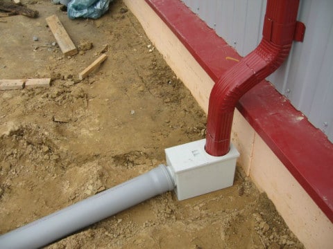
- Installation of risers.
Rainwater is drained from the roof by means of risers, under which point or linear storm water inlets are placed. Vertical drains are attached to the wall with clamps. The calculation of the mounting interval for storm sewer risers is carried out taking into account the material of the pipe.For PVC, clamps are placed at intervals of 2 m, for steel - 1-1.5 m.
- Secured territory.
SNiP provides for the organization of so-called security zones near the location of the storm network. At a distance of less than 3 m from the pipeline, it is forbidden to erect construction objects, plant bushes and trees, arrange a garbage dump, and equip a parking space.
Typical stormwater drainage scheme for a private house
Designing a rainwater drainage system is an important stage in the construction of a residential building or industrial site. This article provides formulas for a rough calculation of the diameter of the pipeline, since they do not take into account such parameters as the friction of water on the inner surface of the pipe, the number of bends and connections in the system, etc. For a more accurate calculation of storm sewers, there are special programs that can be found on the Internet . However, the surest method is to entrust the design to specialists who will take into account all the nuances and offer the most effective and cost-effective option.
Materials for arranging storm sewers
The project documentation should describe the requirements for the components and materials used for the installation of storm sewers. Their selection is carried out as follows.
Pipes. They can be rigid, made of PVC. Another option is corrugated pipes. PVC pipes are usually laid at shallow depths. Corrugated polymer pipes are more durable, and therefore they are used in the construction of sewers with significant depth. It is also possible to lay asbestos-cement or metal pipes. Their specialists from the Mos-drainage company recommend installing under sections of the roadway, parking lots - where an increased mechanical load can act on the pipeline.
Storm water inlets. They can be made of polymeric materials or polymer concrete. They are additionally equipped with siphons, in which small rubbish, dirt, silt settle. Polymer concrete products are used if it is necessary for the receiving device to have increased strength. Plastic storm water inlets are more affordable, they are easier to install, and have a smooth surface. At the same time, plastic is not as strong as fiber-reinforced concrete, and therefore products made of it, as a rule, are installed in private facilities with a small load.
Door trays. Are wide, from above are closed by a lattice. Used to drain the area directly at the entrance to the house. The door tray has an outlet that connects to the storm sewer pipe. The outlet and the pipe must match in diameter.
Wells. They are made of plastic or reinforced concrete. The first option is used much more often due to the affordable price, low weight, simple installation. The well must be selected not only in size, but also in terms of resistance to ascent, strength characteristics, and installation parameters.
In "Mos-drainage" you can order the design of storm sewers, its arrangement and the supply of all necessary materials and components. We guarantee efficiency and high quality of work.
Calculation formula and its description
Before planning a storm sewer system directly on the land, it is necessary to determine how much precipitation can fall over a certain period of time. Depending on the result obtained, appropriate storm water inlets and conductive elements are selected. The indicators obtained for individual zones are added to each other.
A simplified calculation formula for a specific area will look like this:
Qsb = q20 x F x Y
In the table you can see what the given symbols mean.
| Symbol | Description |
|---|---|
| Qsb | The total amount of water collected from a given size area. |
| q20 | Coefficient showing the average value of precipitation in a particular region of the country. |
| F | The square of the surface involved in the collection of water. |
| Y | A coefficient that reflects the amount of moisture that can be absorbed directly into the coating. |

Using the presented map, you can determine the coefficient q20
As for the coefficient that reflects the average amount of precipitation, it is not so difficult to find out, since it is used by local building or design organizations. There are even special cards that allow you to get the required value. The coefficient for determining the amount of moisture absorbed into the coating is already included in the program, so it does not require additional calculation. It is enough to indicate the type of surface layer.
The final result will be presented in several sizes at once. Thus, after the calculations, it becomes known how many liters of rainfall the storm sewer must receive and divert in one minute or second. An alternative option involves measuring in cubic meters per hour.
Save Time: Featured Articles Every Week by Mail
Formulas for hydraulic calculation of storm networks
In order to calculate the diameter of the storm sewer pipe, it is necessary to determine the average flow of rainwater, which depends on the climatic conditions in a particular area.
The limiting discharge (intensity) of rainwater is calculated by the formula:
Qr = q20 Ψ F
where:
q20 is the calculated intensity of rain for 20 minutes;
Ψ is the coefficient of moisture absorption by a certain type of coating (roof - 1.0; asphalt - 0.95; concrete - 0.85; crushed stone - 0.4);
F is the surface area (in hectares) on which it is planned to carry out drainage.

Rain intensity map to determine the q20 coefficient
For the hydraulic calculation of the rain sewer network, it is necessary to make a correction for the filling factor of the free pipeline when a pressure regime occurs (β). Thus, the rainwater discharge is calculated as
Q = Qr β
The coefficient β is determined from the table:
| Rain duration index n | 0,7 | 0,6 | 0,5 | 0,4 |
| The value of the coefficient β | 0,65 | 0,7 | 0,75 | 0,8 |
In turn, the parameter n depends on the geographical location of the object:
| District | Parameter value n |
| Coast of the Barents and White Seas | 0,4 |
| North of the European part of the Russian Federation | 0,48 |
| Center and west of the European part of the Russian Federation | 0,59 |
| Western slope of the Urals | 0,59 |
| Lower Don and Volga | 0,57 |
| Lower Volga | 0,66 |
| Central Siberia | 0,47 |
| Eastern Siberia | 0,52 |
| Western Siberia | 0,58 |
| Altai | 0,48 |
| Coast of the Sea of Okhotsk | 0,31 |
If the slope of the terrain is 1-3 cm per 1 m, then the coefficient β must be increased by 15%. With a larger slope, this parameter is taken equal to 1.
Additional information on the application what is the methodology
So, if the owner of private real estate decided to give the turnkey calculation of storm sewers - that is, under the full control of the developer company, he needs to submit the following technical documents:
- Plans of the land plot - topographical, town-planning. Storm sewers should not interfere with busy roads, make the use of pedestrian sidewalks uncomfortable. In addition, the location of nearby water bodies, other sewer outlets, wells and other structures related to the discharge of moisture is taken into account.
- Geodetic conclusions about the state of soil layers. They take into account the depth of freezing of a given area, the level of water rise during spring and summer, the composition of the soil and movement - capricious soil can swell or, conversely, subside, which is why sewer wells are properly strengthened.
- Possibility of carrying out engineering communications - technical conditions. If the area is waterlogged or drinking water bodies are close to the object, the adjustment of the documentation is serious - neither stagnation of the mass of wastewater nor mixing with clean water should be allowed.
- Terms of reference for the design of stormwater. Specialists will take into account the wishes of the owners, however, they will not deviate from the standard generally accepted rules.
WATCH VIDEO
Contents of the explanatory note: hydraulic calculation according to SNIP
After the expiration of the time allotted for the storm sewer project, the owner receives a document containing the following nuances:
- Design data about the future construction. Drawings and diagrams indicating the technical characteristics of each element.
- The plan of the territory, which indicates the location of the main sewerage nodes, the length of the main routes and the diameter of the drain wells.
- The necessary equipment is indicated - transit, for laying design sewerage networks and stationary for permanent location on the site.
- The financial part is the estimate of the entire enterprise.
For independent design, it is important to use these rules, since the digging of drainage channels will not end. Working drawings are made independently, but they receive official approval. The calculation of storm sewers is carried out taking into account all the features of the system
Storm sewer design
 In addition to wastewater coming from the building, it is necessary to remove precipitation from the site. For these purposes, a special storm sewer (storm drain) is used, consisting of open gutters (ground gutters) that drain a large amount of water into a special central city sewer, a separate home well, an open sewer, and a reservoir located nearby.
It is strictly forbidden to dump such drains into a household septic tank - in the case of frequent and intense rainfall, it will quickly fill up and become clogged with sand and earth contained in the water.
The calculation of storm sewer flows, necessary for the correct design of the drainage system, is made according to the following formula:
Vstormwater runoff=Ev.×S×φ, where:
- Vstorm drains - the volume of storm water that must be diverted through sewerage;
- Osr. is the intensity of precipitation falling in the region (l/sec);
- S is the area from which storm water will be collected for disposal into the sewer, ha;
- φ is the water absorption coefficient of the material from which the runoff to the storm drain will be made.
Based on the calculations, a drainage open tray with a certain flow area is selected.
Calculation example:
It is necessary to calculate the volume of storm water and select the optimal cross-sectional type of drainage trays for a fully concreted area (φ of concrete = 0.85), located in the Moscow region (Av.g = 80 l / s), with an area of 500 m2 (0.05 ha) with a house having a roof (φ=1) with an area of 60 m2 (0.006 ha).
Vstormwater runoff = (Ev.×S×φ) area + (Ev.g×S×φ) roof. \u003d (80 × 0.05 × 0.85) + (80 × 0.006 × 1) \u003d 3.88 l / s.
Based on this amount of precipitation, a sewer storm tray is selected that is capable of passing a volume of water 20-25% higher than the result obtained during heavy rains.
Culvert capacity of various ground drains.
| Type of drainage tray | Cross section, mm | Culvert capacity at a slope of 5 mm / 1m (0.5%), l / s. |
| Plastic | 140 | 5,1 |
| Concrete | 136 | 5,2 |
| Polymer concrete | 92 | 5,0 |
| Polymer sand | 102 | 5,7 |
Using the table below, we can say that storm sewers made of plastic trays with a flow section of 140 mm and a culvert capacity of 5.1 l / s will be most effective.
Designing the location of the sewer system
 At this stage, the following manipulations are performed:
- On the diagram of the built house, the location of plumbing and household appliances - washbasins, bathtubs, washing machines and dishwashers is noted.
- All drain points on the graphic image are connected by pipe lines indicating their actual length and internal diameter.
- On the site diagram, the location of the external sewer network is planned. At the same time, yard communications for draining wastewater flowing into a collector or septic tank should go to their end point at the shortest distance, without sharp and sharp turns.
- According to the requirements of SNiP 2.07.01-89, the sewerage to be laid must be located horizontally (in the light) at least 1.5 m from the domestic water supply, underground gas pipe; 0.5 m from communication lines and power cables.
Optimum pipe slope
 Recommended slope
This characteristic is important in simple free-flow sewers, as it affects the speed of movement of effluents and the performance of the system. It is usually expressed in centimeters per meter of water flow or in% (the height difference of the ends of a meter communication of 1 cm means that its slope is 1%).
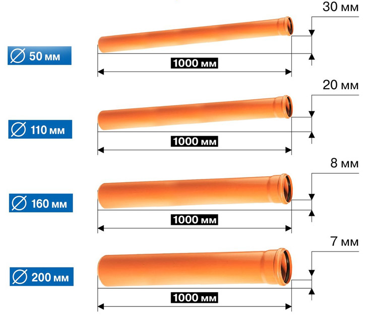
The slope of the pipes depends on their diameter and, on average, for the following sizes is:
- 50 mm - 3 cm / 1 m (3%);
- 110 mm - 2 cm / 1 m (2%);
- 160 mm - 0.8 cm / 1m (0.8%).
With a small slope, the flow will be slow and the pipe will quickly become silted with heavy particles settling on its bottom. Too much inclination of communications also negatively affects their normal functioning - the discharge of a significant amount of wastewater will lead to their delamination and adhesion of the heavy fraction along the contour of the inner walls of the waterway.
Gutter structures
At
open drainage system transverse
street sections are performed taking into account
the planned level of improvement
urban area.
Typical
shoulder road profile
and cuvettes is shown in Fig.8. Surface
runoff from the carriageway, as well as from
areas of the adjacent territory are allotted
into ditches located along the carriageway
parts of the street. Cuvettes suit earthen
with the strengthening of their slopes with stone or
concrete slabs, as well as from finished
reinforced concrete blocks with vertical
walls.
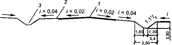
Fig.8.
A typical cross section of a road with
roadsides and ditches:
1
- carriageway; 2 - curb; 3 -
earth ditch
General
street width between "red lines"
reduced (while maintaining the overall
dimensions of the main elements of its division)
due to the bandwidth required for the device
sloping cuvettes of a general profile (Fig. 9).
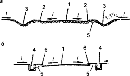
Fig.9.
Scheme of open drainage on the roads
with trays:
1
- the carriageway of the street; 2 - road flow;
3 - paved ditch; 4 - precast concrete
ditch; 5 - bypass tray; 6 - onboard
a rock
Dimensions
the main outlet channel when open
drainage system is determined by calculation.
With improved types of road
coatings arrange a closed system
drainage - cuvettes are replaced with reinforced concrete
pipes and lay them at depth,
ensuring that water drains do not freeze
(Fig. 10).
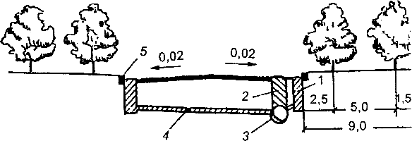
Fig.10.
Scheme of a closed drainage system on the roads
with advanced coatings:
1
- rainwater well; 2 - viewing
well; 3 - drainage pipe; 4 - release
from a rainwater well; 5 - onboard
a rock
Surface
water from the flumes of the road enters
rainwater wells, the drain from which
enters the main sewerage network.
Storm water and manholes
arranged from precast concrete
blocks. They are sized according to
network operating conditions (Fig. 11, 12). By
prefabricated
manholes suit three types
depending on the pipe diameter.
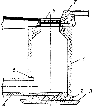
Fig.11.
Scheme of the storm water well:
1
- working chamber; 2 - bottom; 3 - sandy
base; 4 - release from the rain inlet
well; 5 - sealing the hole with concrete;
6 - cast-iron grate; 7 - side stone
On the
large collectors,
arrange special necks, on
which install cast-iron hatches.
For laying a network of storm sewers
use round reinforced concrete pipes,
prefabricated rectangular channels, and with
arrangement of large collectors
design atypical prefabricated structures.
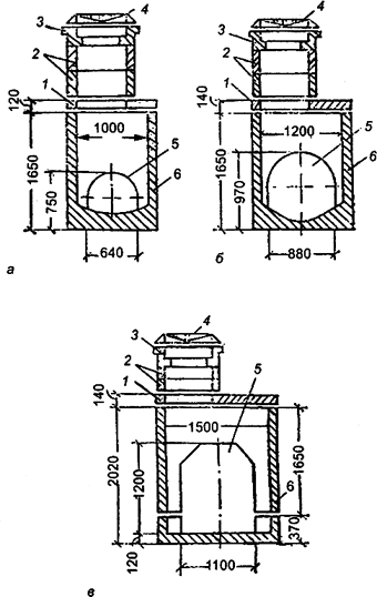
Fig.12.
Schemes of prefabricated manholes in
depending on pipe diameter:
a
- 300-500 mm; b - 600-700 mm; c - 800-1100 mm;
1
- floor slab; 2 - neck ring;
3 - support ring; 4 - hatch with a lid; 5 -
hole for laying pipes; 6 - working
camera
At
laying large diameter pipes and
insufficient depth of their laying
two pipes instead of one
smaller diameter, having the same total
diverting capacity (Fig. 13).
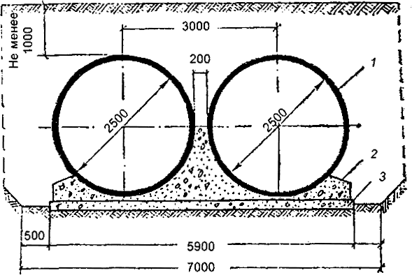
Fig.13.
Scheme of laying two pipes side by side:
1
- reinforced concrete pipe; 2 - concrete
base; 3 - preparation from crushed stone
Minimum
backfill over the top of the pipe structure
drain take at least 1 m. Laying
round pipes with quarter-joints
and the socket is shown in Fig.14.

Fig.14.
Scheme of laying a round pipe with a seal
socket joint and detail:
1
- reinforced concrete pipe; 2 - concrete
base; 3 - preparation from crushed stone; 4 -
pipe socket
Sewer project calculation
Basically, a storm sewer design is always calculated taking into account the average rainfall in a given area, the speed of wastewater movement, as well as the impact of nearby water bodies. This is not surprising, because all these factors make up the amount of water that will be periodically removed by storm systems. That is why such important data should not be left aside.
 In addition to all of the above, any storm sewer project necessarily includes an estimate. Of course, the construction of sewerage requires certain costs. In order to calculate the cost of such a sewer, it is necessary to determine the cost of water collectors, pipes, wells and filters. All this, as well as the cost of the work itself, that is, payment to the workers, will be the estimate.
As a rule, a lot of attention is paid to wells, since they come in different types and are capable of performing a variety of functions, depending on the choice of the customer. For example, some wells can not only collect water, but also distribute it to various streams, purify and sample water, measure flow parameters, and wash out precipitation.
The next step in the storm sewer design is to determine the depth to which the pipes of the system are lowered. As a rule, this is calculated from the diameter of the pipe itself. The minimum depth is 50 cm. The slope of the system is also determined at this stage. Further, depending on the nature of the territory, it is determined what type of water collection will be used. If the area is small and you just need to collect water in some places, then spot water collection is suitable, that is, drains will be installed only in certain places.
If the territory is large enough, then linear water collections will be needed here. As a rule, they are located around the entire perimeter of the site and collect all the water.
And finally, perhaps the most important thing. Regardless of what type of sewerage is used and on what territory the work is carried out, in any case, the project must first of all be guided by sanitary and construction rules, as well as safety requirements, otherwise no inspection will let your project pass further. Carefully calculate all the parameters, follow the safety rules, and then your storm sewer will definitely function correctly and make any site dry.
Introductory concepts
The calculation of storm sewers does not always require the help of professionals, everything can be done by hand, especially if you need drainage for rainwater not on an industrial scale, but on a domestic scale. Having considered an example of calculation, it is permissible to construct structures for an enterprise, its own private buildings, as well as the creation of stormwater in other territories.
The calculation method affects:
- data of landscape, geological features of the site,
- construction specifics of buildings,
- location of engineering communications,
- average rainfall;
- materials to be used for the construction of structures.
When thinking over a storm drain for an enterprise, it is also necessary to take into account the cross-country ability, area of \u200b\u200bthe territory, the presence of access ramps and other structures. The general arrangement of the drainage system is carried out immediately after determining the required stormwater parameters.
Regulatory guidance for calculating storm sewers of different diameters, taking into account the runoff under a slope
The design part of the document is executed in accordance with SNiP 2.04.03-85 and GOST 3634-99, 21.604-82. The rules have not lost force over the years and are used in our time. Documents will help home craftsmen who decide to independently design storm sewers. What they include:
The formulas by which the storm sewer is calculated, the length of the main, the width of the branches, the number and parameters of the slopes of the channels.
Pipe cross section, material of manufacture, related accessories in the form of clamps, fasteners
It is important to indicate the quality of building materials.
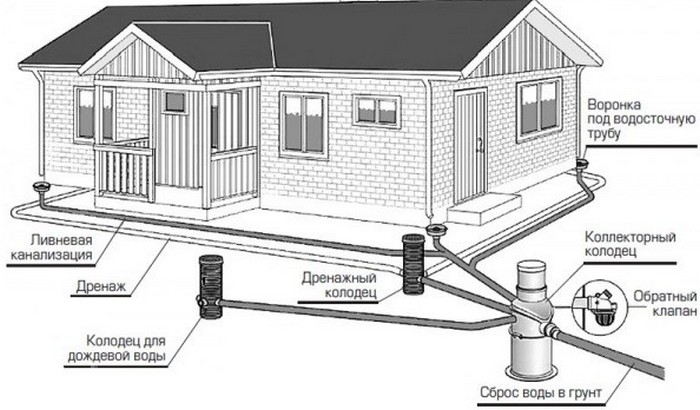
Stormwater device technology .. Scheme of a storm sewer device
Scheme of the storm sewer device
The necessary technical conditions for storm sewers must be endorsed by the relevant state institutions - the architectural department of the city, the BTI, and other bodies related to land and housing departments. If the owner of the site does not have the strength, time and nerves for this, then the best way out is to contact a design organization that is accredited for such approvals.
What is a storm drain design features
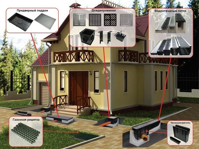
The collection of channels for collecting and discharging sewage is called a storm sewer. External sewerage networks vary in design, but always contain the following elements:
- Guide grooves. Under roof and ground. The latter are equipped with accessories - trays made of reinforced concrete, brick or foam blocks.
- Storm water inlets. Storm funnels located at the corners of the roof, where a lot of precipitation flows down a slope along the gutters.
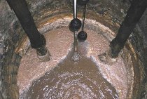
- Collectors. Receiving wells, from where a mass of water is pumped out by the pump as the tank is full.
- Control wells that allow you to monitor the level of wastewater for timely drainage.
Additionally, water supply and sewerage are supplied with filters to protect wastewater tanks from coarse suspensions that can damage pumping equipment.
The simplest system in the form of a ditch leaving the house on a slope is a thing of the past - it has more disadvantages than advantages. Firstly, the soil is washed out, and the runoff becomes smaller, as the walls crumble inward. This will result in overflow during the spring or summer season. Secondly, the site will never get rid of dirt - clay will do its job. Thirdly, there is a risk of mixing waste masses with water from a drinking well located on the site. It is recommended to use the services of specialists in design calculations in order to avoid the described problems.