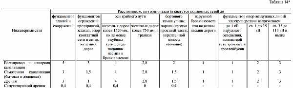
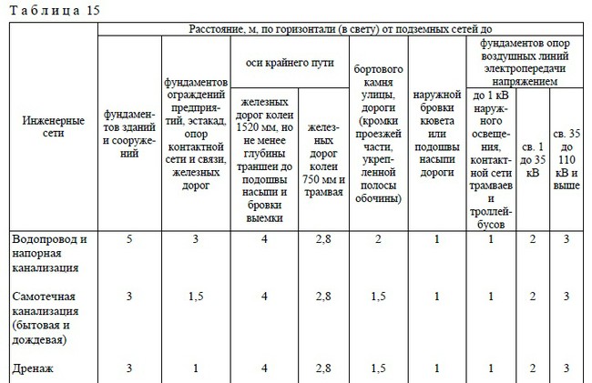
Distance from foundation to sewer
When laying, the distance from the sewer to the foundation of the foundation of buildings should be maintained, sewer pipes should be located in compliance with distance standards.
The sewerage system is laid parallel to the building red lines; when installed on the street, a side with a smaller number of other networks and the largest number of connecting pipes is selected.
The distance to the building should make it possible to carry out installation and repair work, ensure the protection of adjacent pipelines, in the event of accidents associated with soil erosion, the dimensional parameters should ensure the safety of the foundation from being washed away.
When determining the distance from the pipeline to the foundation, the slightest possibility of sewage penetration in case of emergency leaks into the water supply line should be excluded.
Minimum distances from sewers and storm drains to foundations:
- buildings and structures - 3 m, when installing a pressure sewer - 5 m;
- protective fences of enterprises, automobile overpasses, power grid supports, railway tracks -1.5 m;
- railways with a width of 1520 mm gauge not less than the depth of the trench to the bulk base and the edge of the excavation - 4 m;
- rail tracks with a gauge of 750 mm - 2.8 m;
- curbs of streets, reinforced roadsides - 1.5 m;
- external cuvette edge or the sole of the road embankment - 1 m;
- poles of lines of electrical networks passing through the air: - up to 1 kW (street lighting, contact wires of urban electric transport) - 1 m; - 1 - 35 kV. - 2 m; - 35 - 110 kV. - 3m.
Also, building rules regulate the location of the sewer line located in the ground in relation to the root system of trees, the distance from the pipeline to the central axis of the tree is taken at least 1.5 m, with drainage sewerage - from 2 m.
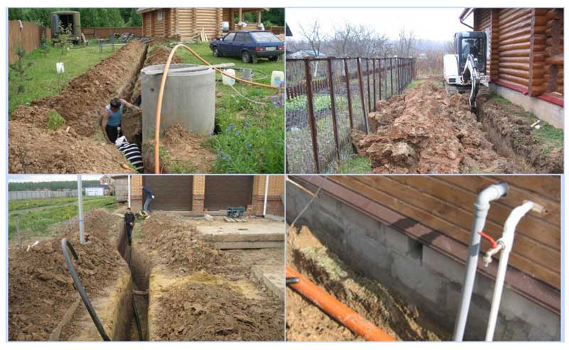
Fig. 6 Examples of laying underground utilities
4 GAS PIPELINE CROSSING WATER OBSTACLES AND RAVIES
5.4.1 Underwater and surface gas pipelines in places where they cross water barriers should be placed at a horizontal distance from bridges in accordance with Table 4.
Table 4
|
water barriers |
Bridge type |
Horizontal distance between the gas pipeline and the bridge, not less than, m, when laying the gas pipeline |
|||||
|---|---|---|---|---|---|---|---|
|
above the bridge |
below the bridge |
||||||
|
from the surface gas pipeline with a diameter, mm |
from an underwater gas pipeline with a diameter, mm |
from the surface gas pipeline |
from the underwater gas pipeline |
||||
|
300 or less |
over 300 |
300 or less |
over 300 |
all diameters |
|||
|
Shipping freezing |
All types |
75 |
125 |
75 |
125 |
50 |
50 |
|
Shipping non-freezing |
Also |
50 |
50 |
50 |
50 |
50 |
50 |
|
Non-navigable freezing |
Multi-span |
75 |
125 |
75 |
125 |
50 |
50 |
|
Non-navigable non-freezing |
20 |
20 |
20 |
20 |
20 |
20 |
|
|
Non-navigable for pressure gas pipelines: |
Single and double span |
||||||
|
low |
2 |
2 |
20 |
20 |
2 |
10 |
|
|
medium and high |
5 |
5 |
20 |
20 |
5 |
20 |
|
|
Note - Distances are from projecting bridge structures |
5.4.2 Gas pipelines at underwater crossings should be laid deep into the bottom of the water barriers being crossed. If necessary, based on the results of the ascent calculations, it is necessary to ballast the pipeline. The mark of the top of the gas pipeline (ballast, lining) should be at least 0.5 m, and at crossings through navigable and raftable rivers - 1.0 m below the predicted bottom profile for a period of 25 years. When performing works by the method of directional drilling - not less than 2.0 m below the predicted bottom profile.
5.4.3 At underwater crossings, the following should be used:
steel pipes with a wall thickness of 2 mm more than the calculated one, but not less than 5 mm;
polyethylene pipes with a standard dimensional ratio of the outer diameter of the pipe to the wall thickness (SDR) of not more than 11 (according to GOST R 50838) with a safety factor of at least 2.5 for transitions up to 25 m wide (at the level of maximum water rise) and not less than 2.8 otherwise.
When laying a gas pipeline with a pressure of up to 0.6 MPa by the method of directional drilling, polyethylene pipes with a safety factor of at least 2.5 can be used in all cases.
5.4.4 The height of laying the surface crossing of the gas pipeline from the calculated level of water rise or ice drift according to SNiP 2.01.14 (high water horizon - GVV or ice drift - GVL) to the bottom of the pipe or span should be taken:
when crossing ravines and gullies - not less than 0.5 m above the GVV 5% security;
when crossing non-navigable and non-alloyable rivers - at least 0.2 m above the GWV and GVL of 2% security, and if there is a stump walker on the rivers - taking it into account, but not less than 1 m above the GWV of 1% security;
when crossing navigable and raftable rivers - not less than the values established by the design standards for bridge crossings on navigable rivers.
Shut-off valves should be placed at a distance of at least 10 m from the borders of the transition. The transition boundary is taken to be the places where the gas pipeline crosses the high water horizon with a 10% security.
Types of gas pipelines
The distance from the water supply to the gas pipeline in each case is calculated from the measurements of a particular section. Nevertheless, a space of about 1 meter is observed horizontally before the water supply.
 Pipeline in the city
When gas workers put gas communication on water pipes too close, this work does not comply with SNiP (SP) standards. After that, you can go to court and complain about unscrupulous gas workers.
In order for the installation to be carried out according to the norms of SNiP, you need to know not only what distance it is desirable to observe between the gas pipeline and the water supply. It is recommended to at least briefly learn about the types of gas pipelines. There are only three of them:
- low pressure line;
- medium pressure gas pipeline;
- high pressure pipeline.
 underground pipeline
Some people who are building a house and intend to conduct communications on their own or are engaged in street construction work often do not know how the water supply pipe from the gas should be located correctly.
For example, the distance from the gas pipeline to the water supply is laid next to it only with the permission of the water utility according to the norms of SNiP
It is important to note that the gas pipeline must be installed at a distance from the foundation of the house
It is worth clarifying that gas is carried into the houses, which, according to its characteristics, has thermal conductivity. The coefficient of such fuel is almost 10,000 kcal/Nm³.
 Pipe laying in winter
The main purpose of gas pipelines:
- The low pressure gas pipeline supplies the resource for the household needs. These pipes are made for buildings such as high-rise buildings, clinics, office buildings, canteens, and educational institutions.
- The medium pressure line is designed for mains or for the operation of a boiler room. In figures, the pressure on such gas pipelines is 0.05 kgf / cm² - 3.0 kgf / cm². They are usually not installed in houses.
- The high-pressure gas pipeline is installed according to the normative rule in order to supply enterprises and workshops with fuel. The pressure varies from 3.0 kgf/cm² to 6.0 kgf/cm².
 Distance standards for communications in accordance with SNiP and SP
Products made of stable, strong polymeric materials are suitable for laying an underground gas pipeline. It is also worth considering that a plastic pipeline is only suitable for transporting low pressure gas, up to 0.05 kgf / cm².
Copper is considered a quality material for laying underground pipes due to its corrosion resistance. But pipelines made of this material can rarely be found in the store. In order for a product made of another metal to last longer, it should be covered with several layers of oil paint.
 Horizontal distances from water pipes according to SP (SNiP)
3 ABOVE GROUND GAS PIPELINES
5.3.1 Aboveground gas pipelines, depending on the pressure, should be laid on supports made of non-combustible materials or along the structures of buildings and structures in accordance with Table 3.
Table 3
|
Placement of elevated gas pipelines |
Gas pressure in the gas pipeline, MPa, no more |
|---|---|
|
1 On free-standing supports, columns, flyovers and whatnots |
1.2 (for natural gas); 1.6 (for LPG) |
|
2 Boiler rooms, industrial buildings with premises of categories C, D and D and buildings of the STS (SNP), public and domestic buildings for industrial purposes, as well as built-in, attached and roof boilers to them: |
|
|
a) on the walls and roofs of buildings of I and II degrees of fire resistance, fire hazard class CO (according to SNiP 21-01) |
1,2* |
|
II degree of fire resistance class C1 and III degree of fire resistance class CO |
0,6* |
|
b) on the walls of buildings of III degree of fire resistance class C1, IV degree of fire resistance class CO |
0,3* |
|
IV degree of fire resistance classes C1 and C2 |
0,005 |
|
3. Residential, administrative, public and household buildings, as well as built-in, attached and roof boiler rooms to them |
|
|
on the walls of buildings of all degrees of fire resistance |
0,005 |
|
in cases of placing the ShRP on the outer walls of buildings (only up to the ShRP) |
0,3 |
|
* The gas pressure in the gas pipeline laid along the structures of buildings should not exceed the values \u200b\u200bspecified in table 2 for the corresponding consumers |
5.3.2 Transit laying of gas pipelines of all pressures along the walls and above the roofs of buildings of children's institutions, hospitals, schools, sanatoriums, public, administrative and household buildings with a mass stay of people is not allowed.
It is forbidden to lay gas pipelines of all pressures along the walls, above and below the premises of categories A and B, determined by fire safety standards, with the exception of the buildings of the hydraulic distribution plant.
In justified cases, transit laying of gas pipelines not exceeding average pressure with a diameter of up to 100 mm is allowed along the walls of one residential building not lower than III degree of fire resistance class CO and at a distance to the roof of at least 0.2 m.
5.3.3 High-pressure gas pipelines should be laid along blank walls and sections of walls or at least 0.5 m above the window and door openings of the upper floors of industrial buildings and administrative and amenity buildings adjacent to them. The distance from the gas pipeline to the roof of the building must be at least 0.2 m.
Low and medium pressure gas pipelines can also be laid along the sashes or mullions of non-opening windows and cross the window openings of industrial buildings and boiler rooms filled with glass blocks.
5.3.4 The height of the laying of aboveground gas pipelines should be taken in accordance with the requirements of SNiP II-89.
5.3.5 On pedestrian and automobile bridges built of non-combustible materials, it is allowed to lay gas pipelines with a pressure of up to 0.6 MPa from seamless or electric-welded pipes that have passed 100% control of factory welded joints by physical methods. Laying of gas pipelines on pedestrian and automobile bridges built of combustible materials is not allowed.
Passage of pipes through the foundation of buildings
The external water supply and sewerage network is introduced into the house through the foundation using steel sleeves of a larger diameter, their standard size for HDPE pipes is 75 mm, for a 110 mm PVC sewer, a pipe with a diameter of 160 mm is used.
The rules for laying external water pipes are regulated by the set of rules SP 31.13330.2012 and includes the following items:
- The entry of communications into the house is carried out through cuttings of metal pipes (sleeves) with a smallest diameter of 50 mm.
- To eliminate the consequences of linear expansions with temperature differences, compensatory bushings are used.
- The distance between the entrance to the foundation base of the water and waste pipes should be from 1.5 m., at the vertical entrance, the gap between the sleeves should be from 0.4 m.
- The diameter of the holes in the load-bearing structures increase the space of the inserted sleeve by at least 2 mm.
- To ensure gravity flow, the sleeve of the sewer pipes is inserted with a slope of 4 - 7 degrees.
- The depth of the pipelines suitable for the house is taken more than 0.7 m from the blind area.

Rice. 9 Scheme of laying the pipe entry into the building
When laying water mains, it is necessary to observe the norms of distances to the foundation - this will avoid negative consequences in the event of a pipeline breakthrough or building subsidence
In domestic housing construction, it is important to adhere to the standards when laying communications, which should be placed in different trenches, then a breakthrough of sewer pipes under any circumstances will not lead to contamination of drinking water
Distance between axes of adjacent technological pipelines
Published: 25.12.2016
Recommended minimum distances between the axes of adjacent process pipelines (in millimeters) in accordance with the “Recommendations for the Construction and Safe Operation of Process Pipelines”.
| Nominal pipeline diameter | Pipelines in isolation | Pipelines without insulation | ||||||
| Wall temperature, 0C | without flanges | With flanges in one plane at medium pressure, MPa | ||||||
| -30..+19 | +20..+600 | 1,6..4,0 | 4,0..6,3 | 6,3..10 | ||||
| 20 | 160 | 120 | 150 | 40 | 80 | 80 | 90 | 90 |
| 25 | 170 | 130 | 150 | 40 | 90 | 90 | 100 | 100 |
| 32 | 190 | 130 | 150 | 40 | 100 | 100 | 100 | 100 |
| 40 | 190 | 130 | 150 | 50 | 100 | 100 | 110 | 110 |
| 50 | 220 | 160 | 180 | 50 | 110 | 110 | 120 | 130 |
| 65 | 250 | 190 | 230 | 60 | 120 | 120 | 130 | 140 |
| 80 | 260 | 200 | 260 | 70 | 130 | 130 | 130 | 140 |
| 100 | 300 | 240 | 280 | 80 | 140 | 140 | 150 | 160 |
| 125 | 340 | 280 | 300 | 100 | 150 | 160 | 180 | 180 |
| 150 | 350 | 290 | 310 | 110 | 170 | 180 | 200 | 200 |
| 200 | 380 | 320 | 360 | 140 | 190 | 210 | 230 | 240 |
| 250 | 430 | 370 | 390 | 160 | 230 | 250 | 260 | 300 |
| 300 | 480 | 420 | 440 | 190 | 260 | 280 | 290 | 320 |
| 350 | 530 | 470 | 470 | 210 | 290 | 310 | 330 | 350 |
| 400 | 590 | 530 | 530 | 240 | 320 | 360 | 360 | 390 |
| 500 | 690 | 630 | 590 | 290 | 380 | 410 | 490 | – |
| 600 | 740 | 680 | 660 | 340 | 450 | 470 | – | – |
| 700 | 780 | 720 | 700 | 380 | 480 | 530 | – | – |
| 800 | 860 | 800 | 800 | 450 | 500 | 610 | – | – |
| 1000 | 960 | 900 | 900 | 560 | 680 | – | – | – |
| 1200 | 1060 | 1000 | 1000 | 660 | 800 | – | – | – |
| 1400 | 1160 | 1100 | 1100 | 760 | 900 | – | – | – |
Recommended minimum distances between process piping and channel walls and/or building walls (in millimeters) in accordance with the “Recommendations for the Construction and Safe Operation of Process Piping”.
| Nominal pipeline diameter | Pipelines in isolation | Pipelines without insulation | ||||||
| Wall temperature, 0C | without flanges | With flanges in one plane at medium pressure, MPa | ||||||
| -30..+19 | +20..+600 | 1,6..4,0 | 4,0..6,3 | 6,3..10 | ||||
| 20 | 210 | 170 | 200 | 70 | 110 | 110 | 120 | 120 |
| 25 | 220 | 180 | 200 | 70 | 110 | 110 | 120 | 120 |
| 32 | 240 | 180 | 200 | 70 | 120 | 120 | 130 | 130 |
| 40 | 240 | 180 | 200 | 80 | 130 | 130 | 140 | 140 |
| 50 | 270 | 210 | 230 | 80 | 130 | 130 | 140 | 150 |
| 65 | 300 | 240 | 280 | 90 | 140 | 140 | 150 | 160 |
| 80 | 310 | 250 | 310 | 100 | 150 | 150 | 160 | 170 |
| 100 | 370 | 310 | 350 | 110 | 160 | 170 | 180 | 190 |
| 125 | 410 | 350 | 370 | 120 | 180 | 190 | 200 | 210 |
| 150 | 420 | 360 | 380 | 130 | 190 | 200 | 220 | 230 |
| 200 | 450 | 390 | 430 | 160 | 220 | 240 | 260 | 270 |
| 250 | 500 | 440 | 460 | 190 | 260 | 280 | 290 | 330 |
| 300 | 560 | 500 | 520 | 210 | 280 | 310 | 320 | 350 |
| 350 | 610 | 550 | 550 | 240 | 310 | 340 | 350 | 380 |
| 400 | 690 | 630 | 630 | 260 | 340 | 380 | 390 | 410 |
| 500 | 790 | 730 | 690 | 320 | 410 | 440 | 520 | – |
| 600 | 840 | 780 | 760 | 370 | 470 | 500 | – | – |
| 700 | 880 | 820 | 800 | 410 | 510 | 550 | – | – |
| 800 | 980 | 920 | 860 | 490 | 590 | 650 | – | – |
| 1000 | 1130 | 1070 | 1070 | 610 | 730 | – | – | – |
| 1200 | 1230 | 1170 | 1170 | 710 | 850 | – | – | – |
| 1400 | 1330 | 1270 | 1270 | 810 | 950 | – | – | – |
In the presented tables, I removed rare (practically unused) pipeline diameters and left only those that are often used in the design and construction of oil and gas facilities at technological sites. Information on “distances” is specially divided into two tables, because this, in my opinion, makes it easier to find the necessary values in the data array.
For example, there is a rack of two pipelines DN80 and DN125 (without insulation and without flanges in the same plane). According to the tables, the center distance between the pipelines must be at least 220 mm. However, experienced designers set the distance between the axles not 220 mm, but 250 mm (or 300 mm).
Believe me, at the construction site, it will be much more convenient for workers to install pipelines at “round” distances (50mm, 100mm, 200mm, 300mm, 500mm, etc.) than, for example, at exact values (237mm, 482mm, 331mm, etc.) .
Location of the water supply
In the area where communications are installed, one should adhere to the norms of perpendicular and parallel distances between pipes conducting gas and water. Also, knowledge of the rules of SNiP will help to competently conduct water supply and gas to the house, while saving on digging trenches for laying communications.
 Main high pressure gas pipeline
The gas pipe must not be installed with pipes carrying flammable liquids and near electrical cables.
The presence of a well or well near the house requires a minimum depth of the pipeline. The installation should be equal to the lower freezing point of the ground with an additional 0.5 m. Water can also be drawn near the foundations of buildings, but subject to certain conditions of SNiP:
- Choose the pipeline material from modern durable polymers.
- The recommended distance from the front of the house to the pipe is preferably up to 1.5 m.
- The distance over which the water supply passes with additional space intended for the possibility of repair, dismantling and other work.
- When laying the pipeline, the likelihood of sewage ingress into the pipeline should be minimized.
- The minimum recommended distance from the sewer to the house is 3 meters.
- The distance to the gas pipeline, in which the pressure is low, is calculated at 1 m.
- Between the high-pressure gas pipeline and the water supply, it is recommended to leave a free space of at least 2 meters.
| Gas pressure | Low | The average | High |
| Retreat from the water supply | 1 meter | 1.5 meters | 2 meters |
Requirements for the placement of water communications
All the norms created for the construction industry are needed to maintain safety in structures and engineering networks. These recommendations apply not only to pipelines, but also to people and the environment.
 Work in the countryside
Some conditions must be observed:
- Too close a distance between communications can lead to the fact that in an emergency, water flowing from the water supply will not seep into the ground before it reaches the foundation of the house. Therefore, the distance from the water supply must comply with the regulations.
- If the required distance between the house and the pipe cannot be observed for various reasons, then the water supply can be laid in casings. This decision should be discussed with the water utility and the pipeliners should be called.
- When there is increased acidity in the ground, this can negatively affect the waterproofing layer and the state of communication. The pipeline will be difficult to open to repair or replace parts. You will have to remove part of the foundation, which is not possible in some houses.
 Near the village
The laying of a gas pipeline and water supply must be designed in advance according to the characteristics of a particular section. This moment will help to avoid errors and problems during the further operation of the pipes.
What should be the distance from well to well
For the construction of a well on the site, there is not enough space with an accessible level of occurrence of the aquifer. The fact is that there are a number of other requirements for the location of the source of water supply, and if they are not met, then the water will not be difficult to be unsuitable for food purposes.
Then we will consider these requirements, fulfilling which, you can avoid the troubles associated with poor water quality.
What are the specific sources of pollution?
The sources of pollution include a number of objects:
- Cesspools and pits;
- Burial places of animals and people;
- Warehouses for pesticides and fertilizers;
- Industry enterprises;
- Sewer facilities
- Landfills, etc.
From this it follows that when choosing a place, it is necessary to focus on the distance from the well to the toilet, and on the distance from other objects of pollution in your own and neighboring areas. This is due to the fact that unwanted elements will enter the water, as a result, it can be detrimental to health.
What are the requirements for the location of underground utilities
The main regulatory document that is followed during construction is SNiP 2.07.01-89, indicating the distances when laying communications relative to each other and other objects in terms of safety and reliability.
During the operation of sewerage, heating and water supply engineering networks, the negative impact on the foundation of the structures of the transported medium in the event of a pipe break should be taken into account. Escaping liquid can wash away the soil foundation base, penetrate into the lower and basement rooms, causing significant damage to buildings.
In the case of laying water-bearing communications near the foundation during the operation of structures, measures should be taken to ensure their safe location relative to the building. When it is not possible to maintain a safe distance from the pipelines to the structure for technical reasons, casings are used to protect communications underground. After agreement with the supervisory authorities, it is allowed to lay a water supply system near the foundations in a case that provides pipe insulation in case of precipitation and protects the foundation itself from destruction in case of water supply damage.
Usually, networks of various types are located on the site with the built house, water, sewer, heating, gas pipes are laid in the ground, and a power cable is pulled. For a safe location relative to each other of various types of highways, it is necessary to know the norms of distances between communications with a parallel and perpendicular arrangement.
Also, knowing the standards will help save money, because some types of communications can be laid in a single trench without significant negative consequences in the event of a pipe break.
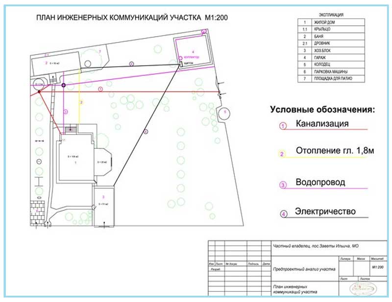
Fig.2 Site plan - example
Urban planning Protected zones of external engineering networks
The composition and distances from construction sites to utilities, i.e. security zones - defined in SNiP 2.07.01-89 *, the current current version of this SNiPa - SP 42.13330.2011. Actually from this SNiP it follows:
Domestic sewer security zone
Distinguish pressure and gravity sewerage. Accordingly, the security zone of a domestic pressure sewer is 5 meters from the pipe to the foundation of a building or structure.
If the sewer is gravity, then according to SNiP, the security zone will be - 3 meters.
In this case, the minimum distance from the fence or contact network supports to the sewerage system will be 3 and 1.5 meters, respectively.
Water supply security zone
The security zone of the water supply is 5 meters from the foundation of the facility to the network. The security zone from the foundation of the fencing of enterprises, flyovers, contact network and communication supports, railways to the water supply system is 3 meters.
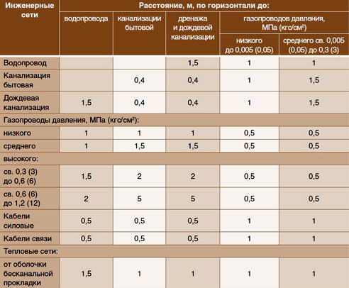
In addition, from SP 42.133330.2011 Table 16 (see details below), you can find the following information regarding the laying of water supply and sewer pipes:
"2. Distances from household sewerage to household and drinking water supply should be taken, m: to water supply from reinforced concrete and asbestos pipes - 5; to the water supply from cast-iron pipes with a diameter of up to 200 mm - 1.5, with a diameter of more than 200 mm - 3; to the water supply from plastic pipes - 1.5.
The distance between the sewerage and industrial water supply networks, depending on the material and diameter of the pipes, as well as on the nomenclature and characteristics of the soil, should be 1.5 m.
Security zone of heating networks
The minimum security zone of heat networks from the outer wall of the channel, tunnel, from the shell of the channelless laying, to the foundation of the building is 5 meters.
Security zone of cables and communication networks
The security zone of power cables of all voltages and communication cables from the network to the foundation of a building or structure is 0.6 m.
And here is the table itself - its first part:
Power line security zone
However, according to the same paragraph, if power lines are laid within the boundaries of settlements under the sidewalk, then:
- up to 1 kW, the permissible security zone from the outermost wires is 0.6 meters to the foundation of the building and 1 meter to the roadway.
- For lines over 1 and up to 20 kW - the security zone will be 5 meters.
According to the same annex, in places where power lines cross navigable rivers, the protection zone for them will be 100 meters. For non-navigable rivers, the protection zones do not change.
In the protected zones of power lines, a special procedure for land use is determined. Within the protected zones, land is not taken away from the owner, but encumbrances are imposed on its use - do not build, do not store, do not block, do not hammer piles, do not drill pits, work using heavy equipment only in agreement with the Grid Organization, etc. P. for more details, see the resolution.
Protected zones, although determined according to the application, are ultimately established by the owner of the networks, information about them is transferred to the cadastral chamber. Paragraph 7 of the resolution states that the grid organization must, at its own expense, place information about the presence, danger, and size of security zones in these same zones - i.e. install appropriate information signs.
Security zone of residential buildings and public buildings
Also in SP 42.13330.2011, you can find a table regulating the distance from residential buildings to garages, car parks and service stations and to public buildings, including educational and preschool institutions.
Protected zone of trees and shrubs
In fact, this table should be understood exactly the opposite, since the distance from buildings to trees and shrubs (green spaces) is regulated.
It follows from it that the minimum distance from the wall of the building to the axis of the tree trunk is 5 meters.
Gas pipeline security zone
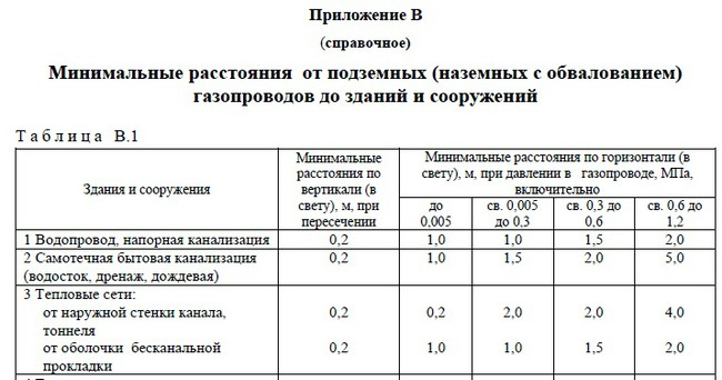
Gas pipelines are distinguished by the device (aboveground, underground) by the pressure inside the pipe (from a few kilopascals to 1.5 megapascals) and the diameter of the pipe. The distance from the gas pipeline to the building is defined in SP 62.13330.2011 in Appendix B.Here are excerpts from this application for the definition of protection zones for underground and aboveground gas pipelines.
Minimum distances between utilities
Even in the joint venture you can find a table regulating the minimum distances between utilities. Distances between water supply and sewerage, power cables and heating networks, between storm sewers and domestic, etc.
Installation restrictions
It is important to consider the fact that high pressure in pipes is dangerous. They must be placed both from residential buildings and from the water supply at a safe distance.
 Distance table from buildings and structures according to SNiP
It is worth knowing the main prohibitions of SNiP:
- The gas pipe must, according to building codes, be protected by two parallel lines located from it. The distance to the lines is calculated differently depending on the pressure.
- The fundamental part of the building must be at a certain distance from the gas pipeline with a low pressure indicator - 2 meters.
- Facade walls should be at a distance of 4 meters from the medium pressure gas communication.
- Gas pipelines with gas under high pressure should be at a safe distance from the house - 7 meters.
- The distance of the pipe supplying gas through a window or doorway should be 50 cm.
- The distance from the pipe to the roof should be about 20 cm.
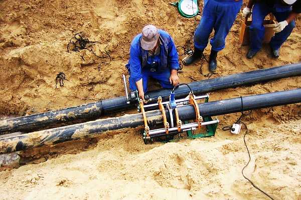 Pipe docking