Determine the category calculated by the National Assembly
Centralized water supply systems are divided into three categories according to the degree of availability of water supply (1, p. 4. 4). According to the assignment, a combined utility and drinking water supply system for a settlement with a population of 3 thousand people was set. Combined drinking water pipelines of settlements with the number of inhabitants in them from 5 to 50 thousand people should be attributed to category II. Category II - it is allowed to reduce the supply of water for domestic and drinking needs by no more than 30% of the estimated consumption and for production needs to the limit established by the emergency schedule of the enterprises; the duration of the decrease in supply should not exceed 10 days. A break in the water supply or a decrease in the supply below the specified limit is allowed for the time of turning off the damaged and turning on the reserve elements or carrying out repairs, but not more than 6 hours.
Pumping stations according to the degree of water supply should be divided into three categories, adopted in accordance with paragraph 4. 4 (1, paragraph 7. 1). In this case, we accept pumping stations according to the degree of availability of water supply of category I (1, note 1, clause 7. 1).
For the established category of the pumping station, the same category of power supply reliability should be taken according to the “Electrical Installation Rules (PUE) 2001 (1, note 1, clause 7. 1).
Electrical receivers of the 1st category are electrical receivers, the interruption of the power supply of which may entail: danger to people's lives, significant damage to the national economy, damage to expensive basic equipment, mass defective products, disruption of a complex technological process, disruption of the functioning of especially important elements of public utilities.
Electric receivers of category I must be provided with electricity from two independent mutually redundant power sources, and a break in their power supply in the event of a power failure from one of the power sources can only be allowed for the time of automatic restoration of power (4, p. 1. 2. 18).
Determine the pressure at normal times.
Nhoz \u003d 1.05 hwater + Nbaka + Ntowers + (Ztowers - Zn), (6. 5)
where hwater is the maximum pressure loss in the conduit, m;
Nbaka - water tower tank height, m;
Ntowers - the height of the water tower, m;
Ztower - geodetic mark at the location of the tower, m;
Zn - geodetic mark of the pump axis, m.
The number of pressure lines from pumping stations of category II must be at least two (1, p. 7. 6). In an emergency, when one of the suction or one of the pressure lines is turned off, the other must ensure the passage of a flow rate equal to 70% of the maximum calculated water flow for household and drinking needs, for the needs of the enterprise according to the emergency schedule (1, p. 8. 2).
We determine the water flow through one pressure line in an emergency, while conditionally assuming that the water supply of the enterprise remains the same.
Qwater \u003d QP2ST 0.7, (6. 6)
where QP2ST is the supply of NS-2 during the operation of two stages for a period of time of one hour, l / s.
Qwater \u003d QP2ST 0.7 \u003d 38.5 0.7 \u003d 26.9 l / s
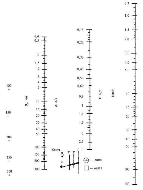
Knowing Qwater and the economic speed of water movement in conduits - from 0.8 to 2 l / s (1, p. 7. 9). using the Shevelev table, we determine the diameter of the conduit pipes and find the speed of water movement in the conduit:
D = 200 mm; 1000i = 6.31; Vwater = 0. 84 m/s
We determine the maximum pressure loss in the conduit hwater in an emergency, using the data from the Shevelev table:
Lwater
hwater = 1000i , (6. 7)
1000
where Lwater is the length of the pressure line, m.
Lwater 1350
hwater = 1000i = 6.31 = 8.5185 m
1000 1000
Nhoz \u003d 1.05 hwater + Nbaka + Ntowers + (Ztowers - Zn) \u003d 1.05 8.52 + 5.03 +25 + (70 - 67) \u003d 42 m
Pumping equipment for the Abyssinian well
A driven or Abyssinian well is a very wise and profitable solution that is chosen for an autonomous water supply system in a private house. The main feature of this water connection is the small diameter (1-2 inches). It is this fact that makes it possible to turn to this type of hydraulic supply, moreover, it is much easier to create a driven well with your own hands than other sources.
Due to the narrow diameter, the use of surface pumping equipment is implied.Now in Russia it is very popular.
Abyssinian wells are quite simple and have a high speed. You can prepare such a source in absolutely any area. In addition, the question of how to connect a pumping station to a well will not confuse even an inexperienced person. The scheme is very simple and the work takes 3-4 hours. For installation, you only need two pairs of hands, since you do not have to deal with complex technical processes.
Until recently, this type of wells was used infrequently, because the water from it was heavily polluted due to poor filtration. But then, a fine mesh was installed at the end of the pipe, which perfectly purifies water from impurities and increases the life of pumping equipment.
To use the Abyssinian well all year round, it is necessary to make a closed hole about 2 meters deep, since at this level the soil no longer freezes. Next, connect all the details and pump the well with a conventional hand pump. You need to pump water until visible transparency is achieved. Then liquid is poured into the system, and the pump starts to work. If water does not appear, then repeat all operations from the beginning. With good tightness of the barrel, the absence of liquid is excluded.
After all these actions, the pump is turned off, and all the water is retained in the system - the check valve does not let it out. From now on, the pumping station installed for the Abyssinian well is ready for operation!
Determining the performance of a pumping station
The performance of a pumping station intended for summer cottages is usually calculated based on the values of peak water intake, which is characterized by the throughput of simultaneously functioning water consumption points. Suppose that the following sanitary appliances can function at the same time in the country:
- shower (standard water flow rate - 0.7 m³ / h)
- toilet bowl (0.4 m³/h)
- washing (0.7 m³/h)
- washing machine (0.7 m³/h)
In total, the maximum productivity of a pumping station designed for a country house in which 3–4 people live should be at least 2.5 m³ / h.
If the pumping station serves a cottage in which two families live, it is necessary to choose equipment whose productivity reaches 4 m³ / h. To service a house for three families, you will need a unit with a volumetric flow rate of 5 m³ / h.
If it is planned to use the pumping station for the purposes of watering the garden and lawn, then it is necessary to increase the performance parameters by another 1 m³ / h. It should be taken into account that the value of this indicator can significantly increase in dry periods (up to 1.5 m³/h).
Pedrollo Corporation offers pumping stations whose volumetric flow rates reach:
- 2.4 m³/h - PKm 60-24SF, PKm 60-24CL, PKm 60-EP I
- 3 m³/h - JCRm 1B-24CL, JCRm 1A-24CL, JSWm 1BX-24CL, JSWm 1AX-24CL, PKm 65-24SF, PKm 65-24CL, PKm 65-EP I
- 4.8 m³/h - 3CPm 80E-EP I, 4CPm 80E-EP I, JCRm 10M-24CL, JCRm 15M-24CL, JSWm 10MX-24CL, JSWm 12MX-24CL, JSWm 15MX-24CL, JSWm 10MX-60CL, Pedrollo JSWm 12MX-60CL, Pedrollo JSWm 15MX-60CL
- 5.4 m³/h - CPm 158-24CL
- 6 m³/h - 2CPm 25/130N-EP I, 2CPm 25/140H-EP II
- 7.2 m³/h - 3CPm 100E-EP I, CPm 170-24CL
- 7.8 m³/h - 4CPm 100E-EP I
Features of operating modes
The towerless system provides for the supply of water directly to the consumer, and in connection with this, the pumps used here must fully ensure the supply in the required volume at peak times of water consumption. Usually, a network operation schedule is built, combined with the pumping station operation schedule, which makes it possible to assess the availability of water at various points in time. In most cases, such systems have a large number of pumps.
If there is a pressure accumulator in the water supply system, the maximum water supply by the station is taken to be less than the maximum possible hourly consumption, and the station’s work schedule is approximated to the water consumption schedule, but they do not always coincide exactly, because due to uneven water consumption with full coincidence of the schedules switching off and on of pumping units will occur too often, which will increase the load on the system.
At the same time, if more water is supplied than necessary, then the excess is fed into the storage tank, and in the future, due to this volume of water, the shortage at peak moments of water consumption is covered.
When calculating the pumping station of the second lift, it is necessary to determine the optimal mode of operation with a low frequency of switching on the pumps and the minimum possible volume of the storage tank. The operation of the station can be two- or three-stage - this is the name of the number of simultaneously turned on pumps.
Recommended operating modes
For systems with a supply of less than 15,000 cubic meters of water per day, it is recommended to use a uniform mode of operation, and with a larger supply, it is not advisable to use this mode, since rather large storage tanks will be required.
So, if the operation of the station is stepped, then the volume of the tank is 2.5-6% of the water supply per day, with uniform operation, the volume of the tank should be within 8-15% of the daily supply. From which it follows that the calculation of the pumping station and the choice of the mode are largely determined by the volume of the available storage capacity.
The choice of operating mode in any case should have an appropriate technical and economic justification, while taking into account local features.
Storage tank capacity
After analyzing the operation of pumping stations, it is easy to see that with a stepped operation mode, it is possible to reduce the volume of the tank and reduce the height of the water rise, which is due to a decrease in the installation height of the tank. In general, the calculation of the pumping station shows that when organizing stepwise operation, the volume of the tank can be three times smaller, but at the same time the area of the station itself will increase, which is due to an increase in the number of pumps used and an increase in the capacity of the tanks for the first lift pumps, which in most cases work evenly.
Also, with the stepped operation of pumping units, the diameter of the water pipes should be increased, since the water passage in this case should be greater than with their uniform operation. At the same time, it has been experimentally established that uniform operation is beneficial for small water pipes, and for large water pipes it is more expedient to use a stepped mode of operation. Medium water pipes are dependent on the length of the conduit, the longer it is, the more uniform work is preferable.
Types of pumping stations of the second lift and their modes of operation
Depending on the existing layout of the object supplied with water and on the location of the pumping station itself in relation to pressure accumulators, such systems are distinguished as:
- reckless;
- with a tower located at the beginning of the network;
- with counter reservoir.
It should be noted that the mode and volume of water consumption are constantly changing and are characterized by great unevenness.
The second lift pumps supply water directly to the consumer, and therefore the operating mode of such a station is determined based on the actual water consumption.
The calculation of the operating mode of the pumping station of the second lift is carried out for the following situations:
- operation of the station during the hours of peak and minimum water consumption per day of its greatest consumption;
- operation of the system if it is necessary to extinguish a fire at times of peak water consumption;
- emergency operation of the station.
In this case, for a system with a counter-reservoir, an additional calculation is made for the case of maximum water transit to the counter-reservoir.
— —
CAUTION 1
|
СÑÑоение аÑÑез ианÑкого баÑÑейна. / - глина. 2 - плаÑÑ-коллекÑоÑ. 3 - извеÑÑнÑк. 4 - аллÑвий. a |
ROOT Ð · Ð Ð ²ÐððÐðоÐðппÐðÐðввв¸Ð¸Ð½Ð²ðвÐðннннннннРРРРРРРРРРРРРРРРРРР¸ дÑенажа ипÑеделÑеÑÑÑгидÑоÑÑаÑиÑеÑким ÑÑое²
a
ROOT Ð Ð ° Ð Ð Ð Ð Ð Ð Ð Ð Ð Ð Ð Ð Ð Ð Ð Ð Ð Ð Ð Ð Ð Ð Ð Ð Ð Ð Ð Ð Ð Ð Ð Ð Ð ÐμÐ Ð Ð Ð Ð Ð ÐμÐ Ð Ð Ð Ð Ð Ð Ð Ð Ð Ð Ð Ð Ð Ð Ð Ð Ð Ð Ð Ð Ð Ð Ð Ð Ðμ ¸ ñ Ð Ð Ð Ð Ð Ð Ð Ð Ð Ð Ð Ð Ð Ð Ð Ð Ð Ð Ð Ð Ð Ð Ð Ð Ð Ð Ð ñ Ð Ð Ð Ð Ð Ð Ð Ð Ð Ð Ð Ðμ
a
Указана вÑÑоÑа. ÐññððÐñÐ °ðÐðÐðÐμÐμÐðÐñÐñÐμÐμμμ ð Ð Ð Ð Ð Ð Ð Ð Ð Ð Ð Ð Ð Ð Ð Ð Ð Ð Ð Ð Ð Ð Ð Ð Ð Ð Ð Ð ° Ð Ð Ð
a
RоÑколÑÐºÑ ÑикÑÐ¸Ð²Ð½Ð°Ñ Ð²ÑÑоÑк Ð Ð Ð Ð Ð Ð Ð Ð Ð Ð Ð Ð Ð Ð Ð Ð Ð Ð Ð Ð Ð Ð Ð Ð Ð Ð Ð Ð ² ² ² Ð Ð Ð Ð Ð Ð Ð Ð Ð Ð ñ ñ Ð Ð Ð ¿Ð¾ÑÑÑоÐμÐ½Ñ ÑÐ ° ÑÑÐμÑнÑÐμ кÑивÑÐμ Ð'Ð »Ñ ÑÐ ° Ð · л иÑнÑÑ Ð³ÑÑпп нР° ÑоÑов, Ñ Ð¿Ð¾Ð¼Ð¾ÑÑÑ ÐºÐ¾ÑоÑÑÑ ÑÑÑÐμÑÑвÐμнно оР± Ð »ÐμгÑÐ ° ÑÑÑÑ Ð²ÑÑиÑл ÐμÐ½Ð¸Ñ back Ðа ÑиÑ. 21 Ð Ð ÐμÐ Ð Ð ÐμÐ Ð Ð ÐμÐ Ð Ð Ð Ðμ Ð Ð Ð Ð Ð Ðμ Ð Ð Ð Ð Ð Ð Ð Ð Ð Ð Ð μl °ÑеннÑÑÑÑÑÑÑÑÑоÑнÑÑÑÑÑÑÑжидкоÑÑей.
a
|
Ð Ð Ð Ð Ð Ð ° Ð ° Ð Ð Ð Ð Ð ° Ð Ð Ð ° Ð Ð Ð Ð Ð Ð Ð ° Ð Ð Ð Ð Ð Ð Ð ° Ð Ð Ð Ð Ð Ð ° Ð Ð Ð Ð Ð Ð Ð ° Ð Ð Ð Ð Ð a |
УвелиÑение вÑÑоÑÑ Ð¿Ð¾Ð´Ñема Ð²Ð¾Ð´Ñ ÑвÐμÑÑ 100 - 120 м ÑÑÐμÐ ± ÑÐμÑ Ð¸ÑпоР»ÑÐ · овР° Ð½Ð¸Ñ Ð² ÑÑÐμмР° Ñ Ð½Ð ° ÑоÑнÑÑ ÑÑÐ ° нÑий многоÑÑÑпÐμнÑÐ ° ÑÑÑ ÑÐμнÑÑоР± ÐμжнÑÑ Ð½Ð ° ÑоÑов, в Ñом ÑРгоÑизонÑалÑнÑм СÑанÑÐ¸Ñ Ð·Ð°Ð±Ð¸ÑÐ°ÐµÑ Ð²Ð¾Ð´Ñ Ð¸Ð· оз. ÐоÐ'ÐμнР· ÐμÐμ и поÐ'Ð ° ÐμÑ ÐμÐμ нР° оÑиÑÑнÑÐμ ÑооÑÑжÐμниÑ, ÑÐ ° ÑпоР»Ð¾Ð¶ÐμннÑÐμ нР° вÑÑоÑÐμ Ð ± ол ÐμÐμ 300 м нР° Ð'ÑÑовнÐμм водÑв озеÑе.
a
r¯r² — вÑÑоÑа деаÑÑаÑоÑа в баÑабан паÑового коÑоа, м; Ñ ññðннÐññÐðÐðнÐðÐμн'ððððμμμ'ðððððð¾¾¾¹ ððð½¾¾¹ Ð Ð Ð Ð Ð Ð Ð Ð Ð Ð Ð Ð Ð Ð SOS.
a
Чем болÑÑе вÑÑоÑа. ÐнР° ÑÐμ говоÑÑ, Ñ ÑвÐμÐ »Ð¸ÑÐμниÐμм вÑÑоÑÑ Ð¿Ð¾Ð'ÑÐμмР° воÐ'Ñ Ð½ÐμоР± ÑоÐ'имо ÑвÐμл иÑиÑÑ Ð¾Ð ± ÑÐμм ÑжР° Ñого воР· Ð'ÑÑÐ ° W, 100° W
a
|
ХаÑакÑеÑиÑÑика ÑенÑÑобежного наÑоÑа. a |
днако вÑÑоÑа Ð ÐμÐðññð¾¾ÐðÐðоÐðÐðоÐññðоÐðÐðоñññÐñÐðооÐñÐðÐðÐðññññññ¸¸¸ññ¾ññññ¸¸¸¸¸¸¸¸¸ñ¸ÐÐ Ð1 ° Ð Ð Ð Ð Ð Ð Ð Ð Ð Ð Ð Ð Ð Ð Ð Ð Ð Ð Ð Ð Ð Ð Ð Ð Ð Ð Ð Ð Ð Ð Ð Ð Ð ÐμÐ Ð Ð ÐμÐ Ð ÐμÐ ÐμÐ ÐμÐ Ðμ Ð ²ÐðÐ Ð Ð Ð Ð Ð Ð Ð Ð Ð Ð Ð Ð Ð Ð Ð Ð Ð Ð Ð Ð Ð Ð Ð ° Ð Ð Ð Ð Ð Ð Ð Ð Ð Ð Ð Ð Ð Ð ° Ð
a
|
Ð Ð Ð Ð ÐμÐ Ð Ð Ð Ð Ð Ð Ð Ð Ð Ð Ð Ð Ð Ð Ð Ð Ð Ð Ð Ð Ð Ð Ð Ð Ð Ð Ð Ð Ð Ð Ð Ð Ð Ð Ð Ð Ð Ð Ð Ð Ð Ð Ð Ð Ð Ð Ð Ð Ð Ð Ð Ð Ð Ð Ð Ð Ð Ð Ð Ð Ð Ð Ð Ð Ð Ð Ð Ð Ð Ð Ð Ð Ð Ð Ð Ð Ð Ð Ð Ð a |
завиÑимоÑÑи Ð¾Ñ Ð²ÑÑоÑÑ Ð¿Ð¾Ð´Ñема Ð²Ð¾Ð´Ñ Ð¸ÑпоР»ÑÐ · ÑÑÑÑÑ Ð¾ÑÐμвÑÐμ и ÑÐμнÑÑоР± ÐμжнÑÐμ нР° ÑоÑÑ, коÑоÑÑÐμ вÑпол нÑÑÑÑÑ Ð¾Ð'ноÑÑÑпÐμнÑÐ ° ÑÑми иР»Ð¸ многоÑÑÑпÐμнÑÐ ° ÑÑми. Ð Ð Ð Ð Ð Ð Ð Ð Ð Ð Ð Ð Ð Ð Ð Ð Ð Ð Ð Ð Ð Ð Ð Ð Ð Ð Ð Ð Ð Ð Ð Ð Ð Ð Ð Ð Ð Ð Ð Ð Ð · Ð ² напоÑа и моÑноÑÑи агÑегаÑов.
a
|
swearing. a |
ÐÐ°Ð²Ð¾Ð´Ð½ÐµÐ½Ð¸Ñ Ð½Ð° ÑÐµÐºÐ°Ñ Ð¿Ð¾ вÑÑоÑе подÑемодÑ, Ð Ð Ð Ð Ð Ð Ð Ð Ð Ð Ð Ð Ð Ð Ð ÐμÐ Ð Ð Ð ÐμÐ Ð Ð Ð ÐμÐ Ð Ð Ð Ð Ð Ð Ð Ð Ð Ð Ð Ð Ð Ð Ð Ð Ð Ð Ð Ð Ð Ð Ð Ð Ð Ð Ð Ð Ð¼ð ° Ð ñ ñ ñμμμμμμ (((((μ (μμμμμμμμμμμððð¸¸ðμμññðμμμμμμμμμμμ ñññ¸¸¸¸μμ ºðððð¸ðμºººððμμμμμμ
a
Performance of pumping stations of the 1st lift
Water supply by the pumps of the station of the 1st lift can be carried out according to three schemes: the pumping station supplies water to the treatment plant; the pumping station supplies water to clean water tanks without purification; the pumping station supplies water without purification directly to the network.
In the first case, the pumping capacity is calculated based on the average hourly flow rate per day with the maximum water consumption, taking into account the water consumption for the own needs of the treatment facilities.
Station Average Hourly Feed 0h, m3/h, determined by the formula
where is the maximum water consumption per day, m3; a - coefficient,
taking into account the water consumption for the own needs of the treatment facilities, depending on the quality of the water in the source, the design of the filters, the accepted washing intensity and the scheme for reusing the washing water; os = 1.04-1.1; T - number of operating hours of the pumping station.
Number of hours of operation of the pumping station T, as a rule, it is taken equal to 24 hours. A smaller number of hours of operation is accepted only with a small value of the daily flow rate and with the design of treatment facilities that allow interruption in operation.
If there are no water treatment facilities in the water supply system (water supply from wells), and pumps supply water to a collection tank, then the total supply of pumps of the 1st lift
where “5 is a coefficient that takes into account the consumption of water for the own needs of the water supply system; a1 = 1,01—1,02.
Such a scheme for supplying water to consumers makes it possible to establish a uniform round-the-clock operation of the pumps of the 1st lift, to reduce the number of wells or their diameter.
The supply of pumps of the 1st lift, pumping water directly into the network, is set equal to the highest hourly flow per day with maximum water consumption (2.
When servicing circulating water supply systems with pumps, the supply of pumps of the 1st lift is taken equal to the average hourly consumption of fresh (additional) water per day with maximum water consumption.
When pumps operate in circulating water supply systems (without pre-treatment of water), the supply of pumps of the 1st lift is taken equal to the average hourly flow rate of fresh (additional) water per day with maximum water consumption.
The required pressure of the pumps of the pumping station of the 1st lift is determined in accordance with the accepted scheme of its supply.
The pressure R developed by pumps when supplying water to a treatment plant or to a tank of a circulating water supply system is determined by the formula
where HG — the geometric height of the rise, equal to the difference between the marks of the highest water level in the receiving reservoir and the lowest water horizon in the intake structure; ANDv, ANDn — pressure loss in the suction and discharge pipelines, respectively.
In cases where pumps supply water directly to the network, the total head is determined by the formula
Where I amG - the geometric height of the rise, equal to the difference between the marks of the calculated (dictating) point of the network and the lowest water horizon in the intake structure; I AMSt. - free pressure required at the design point of the water supply network; X/gn - the sum of pressure losses in water conduits and the water supply network (up to the design point); ANDv — pressure loss in the suction pipe.
Meanings IG, I AMSt., X/?n, ANDTo are accepted according to the hydraulic calculation of the water supply network, carried out for the most unfavorable option for distributing costs in this network. To build a network characteristic, it is necessary to have three to four values of E/rn (for maximum, minimum and intermediate water supply by the pumping station). According to these values, E/gn the characteristic of the network is built and combined with the characteristic of the pumps, then the main parameters of the operation of the pumping station are determined.
Pumping station for a private house what to look for before buying the best models
The existing dependence on the number of floors (especially noticeable in high-rise buildings) is regulated by dividing the water supply system into several segments.Water injection with the help of pumps also affects the change in the rate of hydroflow. In addition, when referring to the tables in the calculation of water consumption, not only the number of taps is taken into account, but also the number of water heaters, bathtubs, and other sources.
Changes in the characteristics of the faucet throughput with the help of water flow regulators, savers similar to WaterSave (http://water-save.com/), are not recorded in the tables and, as a rule, are not taken into account when calculating the water flow on (through) the pipe.
Installation rules

In the hot season, connecting a pumping station to a well with your own hands can take place anywhere, you just need to place it next to a hydraulic source. How to properly install the station in cold weather? Simply position it indoors to avoid pipes freezing.
Installation of a pumping station implies some rules:
- it is necessary to begin the installation of a pipe supplying liquid to the pump, and connecting the station to the house, below the line of possible freezing of soil rocks, and the well itself must be carefully closed and insulated;
- at the end of the pipe, a check valve must be installed, which, at the time the station is turned off, will not allow the liquid to flow back;
- if the resources of the well were used up to the maximum, then water with pollution and earth will flow from the tap. Do not sound the alarm - just turn off the pump and wait for the water to rise to the required level;
- if a natural reservoir is used as a source of water, then it is better to put a grate on the valve, which will more effectively protect water from foreign elements.
Suction depth
 Installations with an ejector are more powerful and productive
There are two types of NS, which differ in the presence or absence of an ejector. The latter is a kind of additional pump (without an electric motor), with the help of which the possible depth of water intake is increased.
Passport suction depth, as a rule, is - 8 m. This is provided that there is no ejector in the station configuration. If this device is present in the water intake system, the indicator may increase. Manufacturers offer pumping stations with a built-in ejector. Practice has shown that such installations are quite capricious. Not always with their help it is possible to raise water from the wells of the declared depth.
A better location is a remote ejector. It is installed at the end of the intake sleeve (plastic pipe or rubberized hose), where it is fixed with a plastic clamp. But this design reduces the efficiency, because the operation of the ejector requires a certain speed of water. The pump lifts the liquid to the surface, part of it drives back to the ejector through a parallel pipeline. The movement of water, first up and then down, reduces the efficiency of the pumping unit.
The suction depth of a station with a built-in ejector is no more than 9 m. With a remote one - no more than 10.5 m. Many sites have an indicator of 45 m. This is misinformation. The National Assembly has several technical characteristics, where 45 meters is the maximum distance from the water mirror inside the well to the last consumer in the autonomous water supply network. The indicator often appears in passport data, but it is not the only one. On the market, you can find stations for which this distance exceeds the indicated value.
Methods for calculating the dependences of water consumption and pipeline diameter
Using the formulas below, you can both calculate the water flow in the pipe, and determine the dependence of the pipe diameter on the water flow.
In this formula for water consumption:
- q is the flow rate in l/s,
- V - determines the hydroflow velocity in m/s,
- d is the internal section (diameter in cm).
Knowing the water flow and d sections, it is possible, using reverse calculations, to set the speed, or, knowing the flow and speed, determine the diameter.If there is an additional supercharger (for example, in high-rise buildings), the pressure created by it and the hydroflow rate are indicated in the device passport. Without additional injection, the flow rate most often varies in the range of 0.8-1.5 m/s.
For more accurate calculations, head losses are taken into account using the Darcy formula:
To calculate, you must additionally install:
- pipeline length (L),
- loss factor, which depends on the roughness of the pipeline walls, turbulence, curvature and sections with shutoff valves (λ),
- fluid viscosity (ρ).
The relationship between the D value of the pipeline, the hydroflow rate (V) and the water consumption (q), taking into account the slope angle (i), can be expressed in a table where two known values are connected by a straight line, and the value of the desired value will be seen at the intersection of the scale and the straight line.
For technical justification, graphs of the dependence of operating and capital costs are also built with the determination of the optimal value of D, which is set at the point of intersection of the curves of operating and capital costs.
The calculation of water flow through a pipe, taking into account the pressure drop, can be carried out using online calculators (for example: http://allcalc.ru/node/498; https://www.calc.ru/gidravlicheskiy-raschet-truboprovoda.html). For hydraulic calculation, as in the formula, it is necessary to take into account the loss factor, which implies the choice:
resistance calculation method,
material and type of piping systems (steel, cast iron, asbestos cement, reinforced concrete, plastic), where it is taken into account that, for example, plastic surfaces are less rough than steel and do not corrode,
inner diameters,
section length,
pressure drop per meter of pipeline.
Some calculators take into account additional characteristics of piping systems, for example:
- new or not new with bituminous coating or without internal protective coating,
- with an external plastic or polymer-cement coating,
- with an external cement-sand coating applied by various methods, etc.
https://youtube.com/watch?v=OWBLxN3iUgE
Read more