DETAILED INFORMATION
An application for more information on this project can be filled out here.
|
Number 51-078-00 |
|||
|
name of the project Installation of pavilions for sectional valves of pipelines of heat networks with a diameter of more than 300 mm |
|||
|
Purpose The equipment and pipelines are placed in a pavilion with a monorail with an external console and an emphasis, the pipelines remain at the marks along the heating network profile |
|||
|
Recommended area of application Heat supply |
|||
|
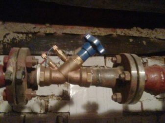
Description According to SNiP 2.04.07.86 "Heat Networks", sectional valves (see figure) with a jumper device 13 between the supply T1 and return T2 pipelines with a diameter of 0.3 of the pipeline diameter, but not less than 50 mm. On the jumper, two valves and a control valve 4 between them with a diameter of 15 mm are provided. SNiP also allows an increase in the distance between the sectional valves, provided that water is drained (using fittings 9) into the storm sewer 10 through a wet well 11 with a damper valve 14. For sectional valves with a diameter of 300 mm, an unloading bypass is provided - a bypass pipeline with a valve 12. For taking readings on the supply and return pipelines, thermometers 7 and pressure gauges 6 are installed. Self-recording flow meters and corrosion indicators can also be installed - two on each pipeline: one for monitoring oxygen corrosion, the other for general corrosion. Pavilions for sectional valves in water heating systems are both underground and aboveground. A feature of the pavilion for sectional valves with an electric drive 8, used on pipelines with a diameter of more than 300 mm, is the need for a monorail with a hoist 2 and a service platform 5. The room must have ventilation (deflector 3), standby electric heating, lighting, a metal door 15, windows made of glass blocks . It is rational to place pavilions on pipeline nodes, combining them with branches to heat consumers. In the known existing and planned pavilions, there are no service platforms, lifting and transport devices (hoists, etc.). When laying underground, pipelines are taken out of tunnels or channels to the zero mark of the pavilion to the ceiling, as a result of which the height increases, additional U-shaped bends of pipelines appear, i.e. additional hydraulic resistance arises, the consumption of metal, building materials, etc. increases. In the proposed layout of equipment and pipelines in the pavilion for sectional valves of large diameters, a monorail with an external console and a stop is provided, which allows the installation and dismantling of equipment and pipelines "from the wheels" by hanging them to the hoist. The service platform is aligned with the zero mark, the pipelines remain at the marks along the heating network profile. The fastening of the suspension of the monorail to the pavilion cover is made on one bolt, in contrast to the existing standard fastenings on four bolts. Such a scheme of the pavilion for sectional valves can be recommended for pipelines of heating networks with a diameter of more than 300 mm. |
|||
|
Advantages over well-known analogues The fastening of the monorail suspension to the pavilion cover is made on one bolt, in contrast to the existing standard fastenings on four bolts |
|||
|
Development stage Implemented into production |
|||
|
Test results Technology delivers consistent results |
|||
|
Technical and economic effect The arrangement of pavilions makes it possible to avoid additional U-shaped bends of pipelines of the heating main, to save the consumption of building materials |
|||
|
Possibility of transfer abroad Can be transferred overseas |
|||
|
Goods receipt date 08.02.2000 |
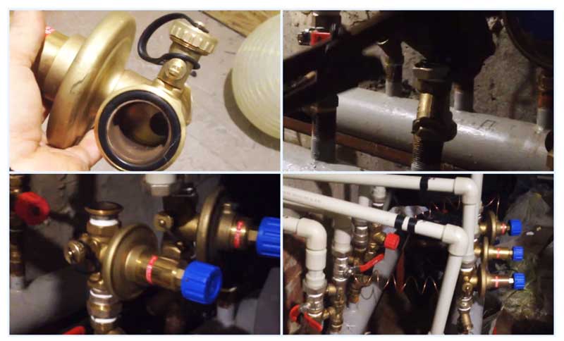
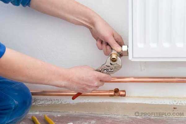
Valve installation
When installing the valve, it is necessary to place it along the arrow on the body, which indicates the direction of fluid movement, to combat turbulence that affects the accuracy of the settings. Choose straight sections of the pipeline with a length of 5 diameters of the device and its location and two diameters after the valve. The equipment is installed in the return branch of the system, a plumbing wrench is enough to carry out the work, installation is carried out in the following sequence:
- Before installation, it is imperative to flush and clean the pipeline system to get rid of possible metal chips and other foreign objects.
- Many devices have a removable head; for ease of installation in pipes, it should be removed in accordance with the instructions.
- For installation, flax fiber with an appropriate lubricant can be used, which is wound around the end of the pipe and the outlet fitting of the battery.
- The control valve is screwed onto the pipe at one end, the second is attached to the radiator with special washers (American adapter), which is placed on the outlet radiator fitting or screwed into the valve, playing the role of a coupling.
Rice. 10 Installation of balancing valves
Selection of valves for radiators
The selection of valves should be made taking into account the following parameters:
- type of locking device;
- technical characteristics of the crane;
- individual characteristics of the heating system.
Types of valves
Three main types of valves are used for installation in a heating system:
- ball;
- conical;
- thermostatic.
Ball valves are installed for autonomous shutdown of heat supply and, due to their characteristics, cannot be used to limit the flow of water into the system.
Shut-off ball valves according to the installation method are divided into the following types:
threaded (faucets are equipped with threads on both sides for connection with pipes). They are mainly produced with a small diameter and are intended for installation in an individual residential heating system;

Threaded shut-off valve
flanged (the device is attached with flanges). They are used in most cases on external highways of heating systems;
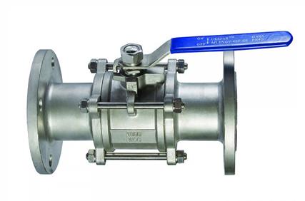
Valve for the heating system, fixed with flanges
welded (installed using a welding machine). Due to the complexity of installation in individual systems, they are practically not used.
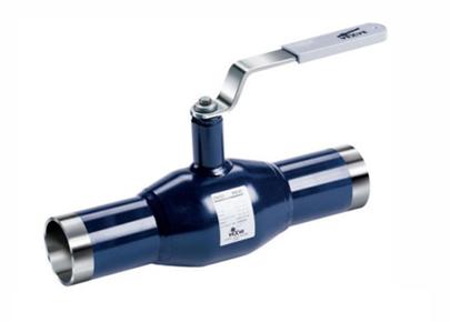
Valve installed by welding
A cone valve, unlike a ball valve, allows you to control the temperature of the incoming liquid. The control valve can be of two types:
straight. The device is installed on a flat area of the heating system;

Crane for level installation
angular. The device is installed at the bend of the supply pipeline.
Bend valve
The main disadvantage of cone valves is manual control, which does not allow you to set a certain temperature regime in the living room.
To maintain the temperature of the liquid in the heating system, a thermostatic valve is installed, which may have:
- manual control. A certain indicator is set on the temperature scale built into the valve;
- semi-automatic control. Temperature setting is made on the push-button display;
- automatic control. The valve maintains the set temperature without human intervention.
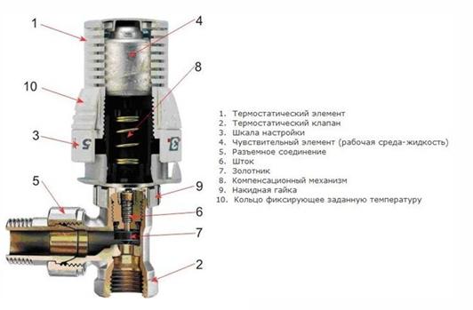
Valve device with adjustable temperature
Which radiator valve to choose? It is necessary to rely on the capabilities of the device:
- complete (shut-off valve) or partial (cone or thermostatic valve) restriction of the incoming liquid;
- temperature setting.
Valve standard requirements
Any radiator valve must meet the following requirements, which are standard for urban heating systems:
- valves for radiators must withstand the temperature of the internal liquid at least 200ºС;
- the operating pressure of the valve installed on the radiator must be in the range of 16 - 40 atm .;
- The valve must be made of materials that are resistant to corrosion and mechanical stress. Quality faucets are made of steel, bronze or brass.
All valves designed for heating systems meet the specified requirements. However, when buying a device, it is recommended to check the operating parameters again.
Accounting for individual characteristics
When choosing valves, it is also necessary to take into account the individual characteristics of the heating system of the apartment, which include:
diameter of the pipes leading to the radiators. The diameter of the valve must fully correspond to the diameter of the pipes;
the position of the valves on the battery. Availability of free space for installation of straight or angle valves;
valve installation method
If the pipes have threads, then it is important to consider its dimensions. If there is no thread, then when choosing a valve, it is necessary to determine the installation method of the device.
Balancing valve for heating system
Existing heating systems are conditionally divided into two types:
- Dynamic. They have conditionally constant or variable hydraulic characteristics, these include heating lines with two-way control valves. These systems are equipped with automatic balancing differential regulators.
- Static. They have constant hydraulic parameters, include lines with or without three-way control valves, the system is equipped with static manual balancing valves.
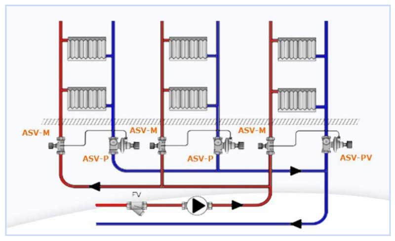
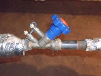
Rice. 7 Balancing valve in the line - installation diagram of automatic fittings
In a private house
A balance valve in a private house is installed on each radiator, the outlet pipes of each of them must have union nuts or another type of threaded connection. The use of automatic systems does not require adjustment - when using a two-valve design, the coolant supply to radiators installed at a great distance from the boiler is automatically increased.
This is due to the transfer of water to the actuators through the impulse tube at a lower pressure than the first batteries from the boiler. The use of another type of combined valves also does not require the calculation of heat transfer using special tables and measurements, the devices have built-in control elements, the movement of which occurs with the help of an electric drive.
If a hand balancer is used, then it must be adjusted using measuring equipment.
Rice. 8 Automatic balancing valve in the heating system - connection diagram
To determine the volume of water supply to each radiator and, accordingly, balancing, an electronic contact thermometer is used, with which the temperature of all heating radiators is measured. The average feed volume per heater is determined by dividing the total value by the number of heating elements. The largest flow of hot water should flow to the farthest radiator, a smaller amount to the element closest to the boiler. When carrying out adjustment work with a manual mechanical device, proceed as follows:
- Open all the adjusting taps to the stop and turn on the water, the maximum surface temperature of the radiators is 70 - 80 degrees.
- The temperature of all batteries is measured with a contact thermometer and the readings are recorded.
- Since the most distant elements must be supplied with the maximum amount of coolant, they are not subject to further regulation.Each valve has a different number of revolutions and its own individual settings, so it is easiest to calculate the required number of revolutions using the simplest school rules based on the linear dependence of the radiator temperature on the volume of the passing heat carrier.
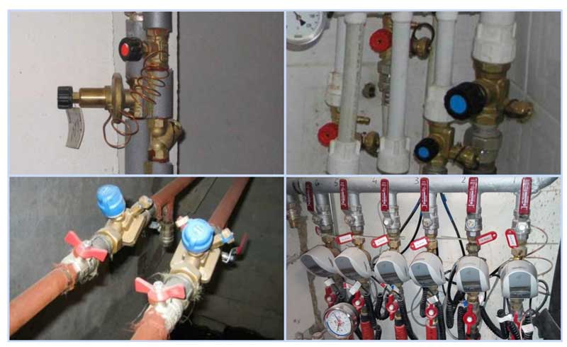
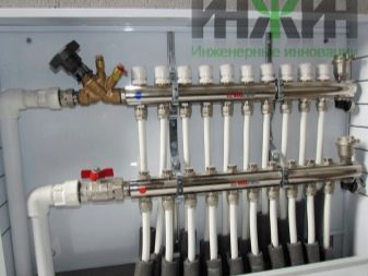
Rice. 9 Balancing fittings - installation examples
For example, if the operating temperature of the first radiator from the boiler is +80 C., and the last +70 C. with the same supply volumes of 0.5 cubic meters / h, on the first heater this indicator is reduced by a ratio of 80 to 70, the flow will go less, and the resulting volume will be 0.435 cubic meters / h. If all valves are set not to the maximum flow, but to set the average value, then the heaters located in the middle of the line can be taken as a guide and similarly reduce the throughput closer to the boiler and increase it at the farthest points.
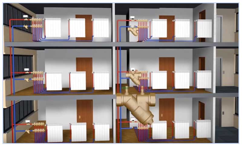
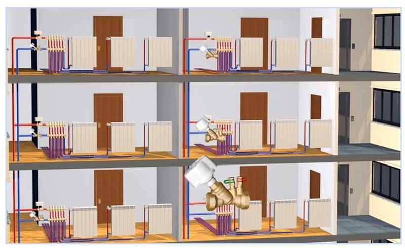
In a multi-storey building or building
The installation of valves in a multi-storey building is carried out in the return line of each riser, with a large remoteness of the electric pump, the pressure in each of them should be approximately the same - in this case, the flow rate for each riser is considered equal.
For setting up in an apartment building with a large number of risers, it uses the data on the volume of water supplied by the electric pump, which is divided by the number of risers. The value obtained in cubic meters per hour (for the Danfoss LENO MSV-B valve) is set on the digital scale of the device by turning the handle.
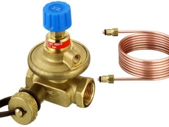
Design and principle of operation
The principle of operation of the balancing fittings is to block the flow of liquid by a retractable valve or a stem, causing a decrease in the cross section of the passage channel. Devices have a different design and connection technology, in the heating system they can additionally:
- Maintain pressure drop at the same level.
- Limit coolant flow.
- Shut off the pipeline.
- Perform the function of draining the working fluid.
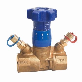
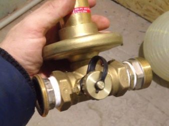
Structurally, balancing valves resemble ordinary valves, their main elements are:
- Brass body with two grommets with an internal or external thread section, designed for connection to a line with standard pipe diameters. Connection in the pipeline in the absence of a threaded fitting with a movable threaded nut (American) is made through its analogues - additional adapters with different union nuts.
- A locking mechanism, by moving which the degree of overlapping of the channel for the passage of the heat carrier is regulated.
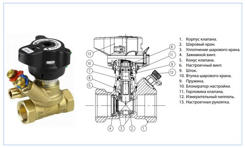
Rice. 4 Danfoss LENO MSV-B manual balancing valve device
- Adjustment knob with scale and setting indicators, allowing you to adjust the flow inside the device.
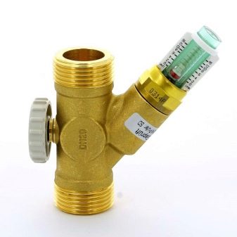
- Modern models are equipped with additional elements in the form of two measuring fittings, with the help of which measurements of the flow volumes (throughput) at the inlet and outlet of the device are made.
- Some models are equipped with a shut-off ball mechanism that allows you to completely shut off the flow, or have the function of draining the liquid from the water supply.
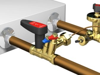
- High-tech modern types can be controlled automatically, for this, instead of a rotary head, a servo drive is installed, which, when power is supplied, pushes the locking mechanism, while the degree of channel overlap depends on the magnitude of the applied voltage.
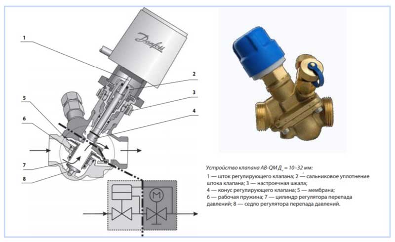
Rice. 5 Danfos AB-QM automatic balancers - design
Why you should use
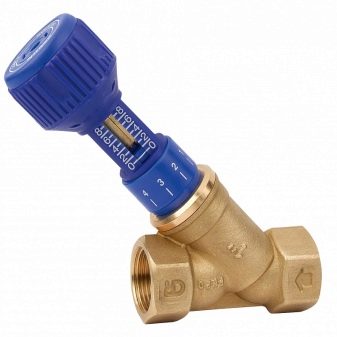
Installing balancing valves in the heating system, in addition to maintaining the same temperature of the batteries, in an individual house brings the following effect:
- Precise adjustment of the coolant temperature allows you to set its value depending on the purpose of the premises - in living rooms it can be higher, in utility rooms, pantries, workshops, gyms, food storage areas using balancers, you can set it to a lower value. This factor increases the comfort of living in the house.
- Changing the coolant flow with the help of a balanced valve regulator, depending on the purpose of the premises, brings a significant economic effect, allowing you to save on fuel.
- In winter, in the absence of owners, constant heating of the home is necessary - with the help of balancing valves, it is possible to achieve adjustment of the heating system with minimal fuel consumption and maintaining a constant temperature in all rooms. This advantage also saves the owners' financial resources.
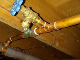
Rice. 3 Manual balancing valves for heating and hot water (DHW) systems in the house
How to remove an air lock
Ideally, gases rise to the highest points of the circuit, where air vents are installed, and are vented from there by valves operating in manual or automatic mode. In practice, errors in the design or installation of the pipeline lead to the formation of air pockets in hard-to-reach places.
To remove such a plug, you need to find its location - by the murmur of the coolant flowing through the airy section, by the relatively low temperature of the pipe or radiator, by the ringing sound when pipes are tapped.
An increase in the temperature of the coolant and / or pressure in the system will help to expel the plug from the autonomous heating system. To apply pressure, it is necessary to open the make-up valve and the drain valve closest to the air lock (in the direction of flow). The water entering the system increases the pressure and forces the plug to advance. After making sure that the plug has exited through the valve (it stops hissing), the system is returned to normal operating mode.
 Removing an airlock from the heating system
In more complex cases, not only pressure is applied, but also temperature. The coolant must not be heated above the maximum allowable values, so as not to disable the heating system.
Important! The regular formation of a cork in the same place indicates miscalculations in the project or incorrect installation. It is recommended to install an air vent in a problematic place by cutting a tee into the pipeline
Installation
The balancing valve, designed to control the heating system, is very easy to install with your own hands. Installation is carried out in the same way as a conventional ball valve is mounted
In principle, it is not particularly important how the valve itself will be placed in space, but the arrow on the body must correspond to the direction of water flow. Otherwise, the valve will begin to create resistance to the coolant
The temperature and pressure of different valves may vary, therefore, having studied the characteristics of your own heating system, it is better to find the most suitable option from manufacturers.
Before the valve, it is necessary to place special protection in the form of a filter. This device will prevent debris and dirt from entering the individual elements of the regulator. In addition, it is recommended to mount the valve in such a way that there are significant straight pipe gaps before and after it. Thus, it will be possible to prevent the occurrence of bends that affect the movement of water. Also, before starting the installation, the pipes must be flushed.
The installation of the valve begins after the inspection of the condition of the pipes is completed - it is necessary to check their integrity and the absence of debris. Then the place where the device will be placed is determined. The parameters of the straight pipe sections before and after the valve should correspond to the following figures: five diameters before the element and two diameters after the element or even more, this will eliminate turbulence.
Then the valve is screwed into the thread of the pipe, pre-equipped with tow.
Control valves for heating radiators
Radiator taps are widely used to connect the heating pipeline to the battery. This is a shut-off valve that allows you to control the flow of hot water or turn off a damaged section of the main. Also, its task is to discharge the coolant and prevent the appearance of air pockets.Ordinary ball-type valves can only be in the “open / closed” position and are not recommended for tapping into the heating system, while special shut-off devices (having a similar design) allow you to smoothly regulate the circulation of the coolant and contribute to more efficient heat transfer.
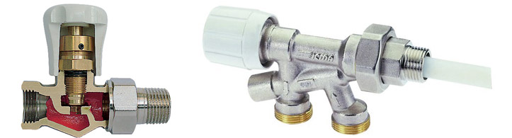
In fact, such products are shut-off and control valves that are maximally protected from corrosion. The material is brass (sometimes with the addition of lead) or high-quality propylene. In the first case, the radiator tap is attached to a threaded fitting, in the second, welding is used. From above, the metal is covered with a protective layer of chromium or nickel (by sputtering). The part that regulates the flow of the coolant is called a thermal head, it is characteristic only for taps of this type. Appearance and design look aesthetically pleasing; devices are installed:
- On risers in apartments with centralized heating, in order to divide into sections for sequential repairs.
- On bypasses - to switch the pump.
- Near the heating radiator, for easy dismantling and repair.
- At points of possible accumulation of air.
Depending on the method of controlling the flow of the coolant, there are:
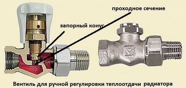
- conventional control valves for the radiator;
- devices with a thermal head (they are also called thermostatic);
- models with a thermostat for heating batteries.
1. Control valves.
They, in turn, are divided into straight and angular types (mounted depending on the supply of coolant). This design allows you to adjust the flow rate exclusively manually, which is not always convenient. The taps are hermetic, they do not allow leaks, and most importantly, they protect heating radiators from hydraulic shock when filled with water. They do not have a temperature determination scale, the setting is performed with an error. Conventional radiator control valves are best used when assembling an individual heating system. Although their appearance is quite aesthetic, which is why they look good in the office.
2. Devices with a thermostat.
Control over the flow rate of the coolant in this case is carried out using:
- Conventional two-mode ball valves.
- A cone valve that allows you to leave the valve in an intermediate position. A slight disadvantage is the manual reset and the need to keep track of the current one.
- An automatic thermostat mounted in a hole in front of the heating radiator.
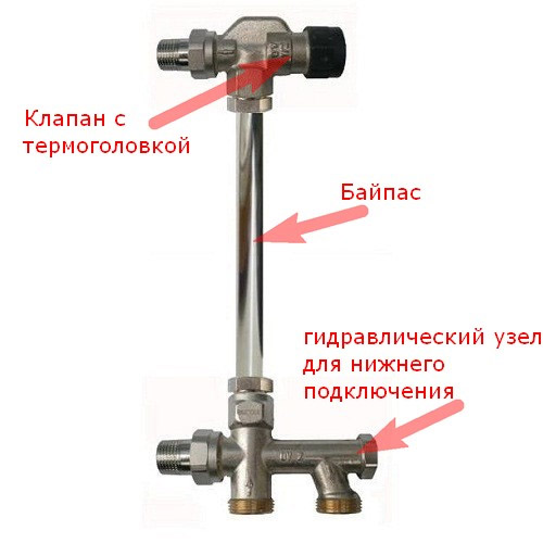
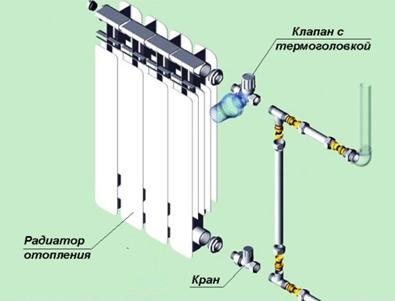
The principle of operation of the valves is based on a change in the permeability of the coolant entering the radiator, depending on the temperature in the room. Their tie-in contributes to energy savings and allows you to create local zones with the desired heat transfer. Valves with a thermostat are installed in a one- or two-pipe heating system; in the first case, they cannot be mounted without bypasses.
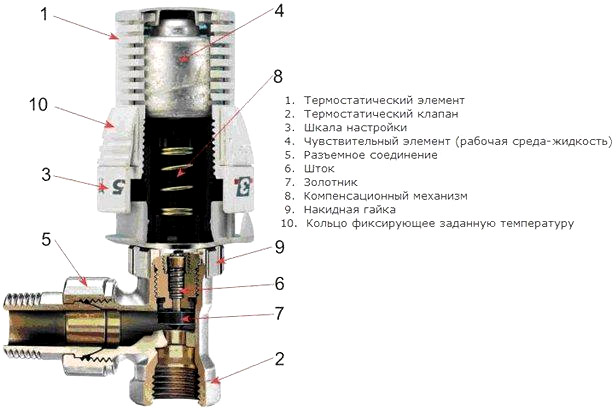
3. Thermostatic radiator types.
These are temperature control devices. The thermal head is a ring with a sensitive element that reacts to thermal fluctuations and changes the amount of flow inside the heating circuit. Varieties with manual and automatic adjustment are produced. In the first case, the temperature changes independently, in the second - autonomously: when a certain value is exceeded, the siphon with liquid increases its volume and changes the position of the stem. Installation is permissible both in one- and two-pipe heating systems, thermostatic devices are suitable for any connection scheme: side, bottom, diagonal.
Such taps and valves for radiators are cost-effective, despite the high cost. They independently maintain the parameters of the heating system at a given level, protect batteries from freezing and reduce gas consumption, therefore they are especially relevant for private houses.But accurate tracking requires taking into account certain operating conditions, namely: faucets with a thermal head are not closed by furniture or other materials, plus they should not be exposed to direct sunlight. If these conditions are not feasible, then it is worth buying another type of valve for the heating radiator.
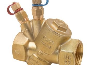
Peculiarities
Modern heating systems are characterized by uneven distribution of heat in individual rooms. The amount of heat depends on the flow rate of the coolant, and the flow of water is just controlled by the balancing valve. If this device is not used, then the amount of heat received will decrease, moving away from its source. Accordingly, there will be different temperatures at different points in the network.
Previously, in simpler systems, this problem was solved by installing pipes with certain diameters or installing special throttle washers. The latter are characterized by a certain passage size, which ensures the supply of the required volume of water.
The design is a specific valve, with which the flow of the coolant is regulated. Sometimes, as an addition to this mechanism, two fittings are built in, which measure the pressure in different zones in relation to the regulating mechanism. In addition, it connects to a capillary tube to coordinate with other controls.
There are two types of these valves: manual and automatic.
The first type, as the name suggests, is manually operated. Products are inexpensive and therefore are the most common. By changing the pressure difference and water flow, they are able to adjust both individual sections and the whole system. In addition, at control points it will be possible to monitor the performance of the working environment, and in the event of a breakdown, turn off any fragment and arrange repair work. Unfortunately, the adjustment of such valves is carried out under the condition of a constant flow of coolant. If it changes, then the system will not be able to function. Therefore, it is better to install such models in private homes and with a simplified heating system.
Automatic valves are devices that do not require human intervention. They independently regulate the volume of the spent coolant or the pressure difference. Some models can work together with impulse piping, simultaneously controlling both flow and differential pressure. It is also worth adding that very often measuring instruments are attached to the balancing valves to make it less difficult to debug the system.
Automatic devices are attached to both the inlet and return pipelines. They are interconnected by a thin tube, thanks to which the valve moves and the water flow is blocked depending on pressure surges. Such a device is configured once and does not require further adjustment.
Valve models may differ depending on the heat carrier (steam, water or glycol solution), type of building (private house or ordinary high-rise building), installation location (on the supply or return pipeline), working environment (at what pressure, temperature and volume of distilled water does the device). Finally, valves can exhibit other features, such as pressure control and be equipped with additional devices such as a measuring orifice.
Adjustment of balance valves
To balance heating in a private house, hand-held devices of the required diameter are selected, selecting and adjusting them using the appropriate diagram attached to the passport. The initial data for working with the graph are the flow rate, expressed in cubic meters per hour or liters per second, and the pressure drop, measured in bars, atmospheres or Pascals.
For example, when determining the position of the adjustment indicator of the MSV-F2 modification with a nominal diameter of DN equal to 65 mm. at a flow rate of 16 cubic meters / h. and pressure drops of 5 kPa. (Fig. 11) on the graph, connect the points on the corresponding scales of flow and pressure and extend the line until the conditional scale of the Ku coefficient intersects.
From a point on the Ku scale, draws a horizontal line for a diameter D equal to 65 mm., Find the setting with the number 7, which is set on the scale of the handle.
Also, for the selected diameter of the device, its adjustment is carried out using the table (Fig. 12), according to which the number of spindle revolutions corresponding to a certain flow is determined.

Rice. 11 Determination of the position of the valve scale at a known pressure and a certain water supply

Rice. 12 Example table for manual adjustment
Valve installation
The product must be installed in accordance with the following guidelines:
- it is more expedient to install the valve at the entrance to the heating radiator;
- The installation height of the device is regulated by the manufacturer and averages 40 - 60 cm from the floor. By default, all valves are calibrated exactly to the temperature at this level. If this rule cannot be observed, then additional configuration of the device is required;
- The thermostatic head on the valve must be installed horizontally. If you install the head vertically, then warm air from the heating pipe will interfere with the normal operation of the sensor;
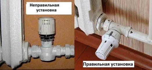
Optimum location of the thermocouple on the pipe
if the valve is installed on a single-pipe heating system, then a bypass will be required (an overlap through which the liquid will pass if its movement through the radiators is restricted).
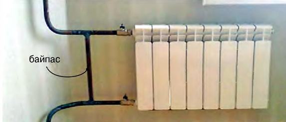
Additional jumper between pipes
The thermostatic valve is connected according to the following scheme:
- fluid is drained from the heating system. In an apartment building, it is possible to drain only with the assistance of employees of the service organization, since the valve is located in the basement;
- a tie-in is made into the heating pipe in the selected place;
- threads of the corresponding parameters are cut at the ends of the pipes;
- the valve, the thread of which is pre-treated with a hermetic thread (flax, Tangit Unilok, and so on), is installed in the prepared place using an adjustable wrench;
Scheme for the correct installation of a thermostatic valve
On each device, arrows indicate the direction of fluid flow. If the valve is installed incorrectly, it will not work properly.
- the tightness of the connections is checked;
- thermocouple is being adjusted.
If the valve is already installed in the pipe, then see the video on how to mount the thermostat.
Having certain skills and knowing the basic requirements, you can install a thermostatic valve on your own.