One-pipe connection diagram with a boiler
Scheme of connecting a gas single-circuit boiler.
The connection scheme for a gas boiler can be flow and circulation. In the first case, the coolant flows by gravity, leaving the heating boiler. In the second case, a special pump is used, which provides forced movement of the coolant. This ensures fast and even heating.
In the first case, a single-pipe connection scheme is used, an example can be seen in Fig. 2. This is a serial connection, which has one drawback. If the temperature drops in one part of the system, it automatically starts to decrease in the rest. Such a scheme allows the coolant to circulate through the circuit on its own, that is, pumps are no longer required. This makes installation a little cheaper, but filling comes from a boiler with a higher pressure than is possible with a two-pipe system.
Gas boiler connection diagram.
Often a single-pipe scheme with a boiler is also called Leningrad, it is recommended to use steel pipes for it, although today they are quite successfully replaced with plastic ones. Radiators should be steel or cast iron, this ensures that there are no large heat losses. Aluminum is almost never used, since heat loss during the movement of the coolant will be significant. This is especially evident in a two-story house. If aluminum radiators are used, then when water rises from the first to the second floor, it cools quickly, that is, the quality of heat is far from what is required. Many recommend installing two boilers, one for each floor or wing of a large building, but it is better to provide for a different heating scheme. It will be much cheaper.
In a single-pipe system, water is supplied to the radiators from the bottom up, but passing in a circle, it cools down a lot, so the last links in this chain get very little heat. The coolant is returned to the boiler already cooled down.
Two-pipe connection diagram with a boiler
Connection of a double-circuit gas boiler.
A two-pipe scheme can be used to connect the heating system. The coolant here will move up along one separate line, after returning back to the boiler along a completely different one. In such a system, as a rule, forced circulation of the coolant is used, i.e., the installation of a circulation pump is required. But on the other hand, the system warms up much faster, it loses less heat when transported to radiators.
Such a decrease in heat loss is due to the fact that for each radiator it is possible to install a special heat regulator, while the rest of the components of the entire system do not suffer any damage. The installation of this system with a boiler is very different from a single-pipe system, for which the installation of regulators is simply impossible. An example of such a boiler connection scheme is shown in fig. 3. For installation, according to this scheme with a boiler, you can use different types of pipes, radiators, everything warms up evenly and correctly.
Scheme of connecting a gas double-circuit boiler directly.
The connection of the system with the boiler is carried out in several ways, one of them involves the supply of coolant to and from the radiator from one side of the equipment. On the other, ordinary plugs are placed, the return pipe goes from below, while the coolant enters from above. But if the radiator has more than 15 sections, then such a scheme is not used due to large heat losses. In this case, a connection scheme is used when the coolant is supplied from below on different sides of the equipment.This method is effective when all pipes of the heating system are laid under the floor, exits are organized only at the places where heating radiators are installed. But there are also disadvantages: the coolant may not completely warm up the radiator from the bottom to the top, so cast-iron radiators are not used, preference is given to panel ones, which are best heated.
When the lower connection scheme is performed, it is also necessary to provide for an emergency shutdown from the coolant supply. This avoids leaks in the event of a malfunction of the entire heating system. If all conditions are met correctly, then heat loss will be minimized, they will be approximately equal to 2%.
Connecting the heating boiler and performing the entire wiring of the house system is an important and complex process. It is necessary to strictly follow all the norms and recommendations, having previously calculated which elements should be included in the connection diagram, what type of wiring for heating you want to choose.
Connection to one system of two boilers
It is possible to combine two heaters using manual and automatic control.
Connection with manual control
Turning on and off the boilers is carried out manually due to two taps on the coolant. The binding is carried out using shut-off valves.
Expansion tanks are installed in both boilers, which are used simultaneously. Experts recommend not to completely cut off the boilers from the system, but simply connect them to the expansion tank at the same time, blocking the movement of water.
Connection with automatic control
A non-return valve is installed for automatic adjustment of two boilers. It protects the shutdowns of the heating unit from harmful flows. Otherwise, the method of coolant circulation in the system is no different from manual control.
In an automatic system, all main lines must not be blocked. The pump of the working boiler drives the coolant through the non-working unit. Water moves in a small circle from the place where the boilers are connected to the heating system through an idle boiler.
In order not to consume most of the coolant for an unused boiler, check valves are installed. Their work should be directed at each other so that the water from the two thermal equipment is directed to the heating system. Valves can be put on the return flow. Also, with automatic control, a thermostat is needed to regulate the pump.
Automatic and manual control is used when combining different types of heaters:
- gas and solid fuel;
- electric and wood;
- gas and electric.
It is also possible to connect two gas or electric boilers to one heating system. Installing more than two connected thermal units leads to a decrease in the efficiency of the system. Therefore, more than three boilers are not connected.
Parallel connection of boilers pros and cons
We have considered the main boilers above. Now consider the connection of backup boilers, which should be in the system of any modern home.
If backup boilers are connected in parallel, then this option has its pros and cons.
The advantages of parallel connection of reserve boilers are as follows:
- Each boiler can be connected and disconnected independently from each other.
- You can replace each heat generator with any other equipment. You can experiment with boiler settings.
Cons of parallel connection of backup boilers:
- We will have to work more with boiler piping, solder polypropylene pipes more, weld steel pipes more.
- As a result, more materials, pipes and fittings, and valves will be used.
- The boilers will not be able to work together, in a single system, without the use of additional equipment - hydraulic arrows.
- Even after using the hydraulic arrow, there remains the need for complex adjustment and coordination of such a system of boilers according to the temperature of the water supply to the system, and.
The indicated pros and cons of parallel connection can be applied both to the connection of the main and reserve heat generator, and to the connection of two or more reserve heat generators on any type of fuel.
Connection to the gas pipeline and installation of the chimney
The first process should be done by specialists of the company that supplies gas. They must first check that the boiler is installed correctly and that all requirements are met. After they connect the device and issue a document that allows you to use the gas unit.
This need is dictated by the fact that all gas-powered devices are dangerous, and if installed incorrectly, an explosive situation may arise in the future.
To connect to the gas pipeline, you need to prepare:
- Tap.
- Mesh filter. It will carry out gas purification, so that the burner will not clog and will be able to function for a very long time.
Partially about the chimney has already been mentioned. It was about a coaxial chimney. It is typical for boilers with a closed chamber (mainly these are wall-mounted options). Also, floor units have such a camera. However, most of them are equipped with an open chamber. This means that air enters the combustion chamber from the room, and good draft is in demand for the removal of carbon monoxide. And for this you need to make a high chimney with your own hands.
The chimney is mounted like this:
- Install vertical stainless steel pipe. fixing it with a special fastener. Its height should be such that the upper end protrudes 0.5 m above the roof ridge. At the same time, they try to make as few turns and horizontal sections as possible. If the latter cannot be dispensed with, then they cannot be made longer than 1 m.
- Connect this pipe to the boiler.
- All parts of the chimney that will be in contact with cold air are thermally insulated. For this, it is better to use basalt wool.
- A special umbrella is placed at the top.
Installing a solid fuel boiler Connecting a solid fuel boiler and a gas boiler to one system Selecting and installing a gas fireplace Installing a heating boiler in a private house
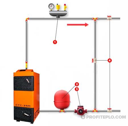
Parallel connection of boilers
When connected in parallel (in the event that the automation of one of the boilers is turned off), water from the return flows through the switched off boiler, overcoming the hydraulic resistance of its circuit, which means additional electricity consumption for the circulation pump. Plus, the return (cooling), having passed through the non-working boiler, is mixed with the supply from the remaining boiler in operation, which, in turn, has to increase power in order to compensate for the admixture from the return. To prevent this from happening, the master plumber has to shut off the pipelines manually (using valves), or install automation equipped with servo drives.
Connecting the boiler to radiators and hot water
This process is performed in the following sequence:
- Do-it-yourself installation of ball valves on the boiler nozzles. To ensure sealing, tow, fum-tape or thread are wound on the threads on the nozzles. It should be added that before fixing valves or filters, one of these elements must always be wound on the threads of metal pipes. If you plan to use polypropylene or metal-plastic pipes, you will have to solder and use special fittings. The features of these processes can be found in various videos.
- A pipe is connected to one tap to supply the coolant to the heating system installed in the house.
- If necessary, mount the security group.
- An expansion tank is placed on the return pipe of the heating system (of course, if it is necessary).
- Carry out the installation of a ball valve and a water purification filter. The latter must be mounted on a horizontal section of the pipeline. It is also possible on a vertical pipe, however, in this case, you will have to use a special version of the filter. It is installed in such a position that the direction of the arrow depicted on it coincides with the direction of movement of the coolant.
- After the filter, a second ball valve is placed. These taps are necessary to facilitate filter cleaning. They are covered with their own hands and the filter is cleaned.
- Connect the return pipe from the heating system to the boiler.
- Connect the "hot" DHW pipe to the tap located on the desired pipe.
- A water pipe is cut into the return line from the DHW. Of course, a ball valve is placed at the beginning of this pipe. It will stop the flow of cold water after it fills the entire heating system and hot water installed in a private house.
- A ball valve, a water purification filter, a magnetic filter and a ball valve are placed on the return pipe from the hot water supply before entering the boiler.
There was no mention of a circulation pump. Wall-mounted double-circuit boilers always have it. For floor boilers designed for natural circulation of the coolant, it is not needed. If a device for natural circulation was previously installed. and then I wanted to make the movement of the coolant forced, I would have to install two circulation pumps: one on the return line of the heating system, the other on the return line of the DHW.
Rules for installation on a wall or floor
The gas unit must be placed inside a separate room. which meets the following requirements:
- There is a window that can be opened at any time.
- Availability of existing ventilation.
- The presence of gas and water pipes.
- The presence of a socket to ensure the operation of the circulation pump and electronics. Of course, it should be the end of a separate branch that extends from the electrical panel. This cable must be connected to a separate circuit breaker. In addition, grounding is mandatory.
There are also requirements regarding the correct placement of the boiler in the house. They are:
- The distance between the main element of the heating system and other gas appliances must exceed 20 cm.
- There should not be a window nearby.
- The distance between the boiler and the socket must be at least 0.5 m (at least, such recommendations are given by manufacturers). In general, the farther the outlet from the boiler, the better. It is worth adding that some models have a power cable without a plug. This means that the wire must be connected with your own hands immediately to the circuit breaker located in the electrical panel.
- The space between the side walls of the boiler and adjacent walls or objects must be greater than 15 cm.
- The wall on which or near which the boiler is installed must be solid and covered with non-flammable materials. If the wall is such that it can catch fire, it should be covered with at least 3 mm non-combustible material. This is often noted in various videos.
Parallel connection
Parallel connection is most often used to connect to a large-capacity boiler or TTK (solid fuel boiler), i.e. 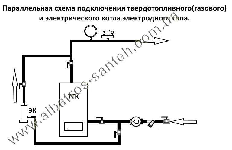 more than 50 liters. This is done in order to cut off (not spend additional energy on heating) the unused volume of coolant in the main or TTC.
As a rule, such systems are more expensive due to the need to install additional equipment on the electric boiler circuit, i.e. additional safety group, expansion tank and shutoff valves.
A parallel system can operate in manual and automatic mode (unlike a serial one, where the principle of connection makes it possible at the lowest cost to implement only automatic or semi-automatic operation of the EC in tandem with the TTC or GC)
In order for the parallel system to function in manual mode, shut-off valves (ball valves) must be installed in the necessary places or a By-Pass system is embedded, which generally leads to an increase in the cost of such a connection by $40-80.
If you organize automatic operation with parallel connection of the TTC (GK) and EC, you need to insert a three-way zone valve, a servo drive and an additional thermostat, from which a command will be sent to subsequently switch the heating circuit of the TTK (GK) to the heating circuit of the EC. The use of such a system as a whole will increase the cost of materials for connection by approximately $ 80 - $ 120. I repeat, such a connection scheme is highly desirable and economically justified in the future in the case when the volume of HA or TTK, together with the total volume of the heating system, significantly exceeds the recommended proportion - the ratio of the total volume of the system coolant per 1 kW of boiler power.
This ratio varies on average (20
Ways to connect wood and gas boilers into one system
Since the wood-burning boiler operates in an open system, it is not easy to combine it with a gas heater that has a closed system. With an open-type piping, the water is heated to a temperature of one hundred degrees or more at the highest high pressure. To protect the overheating of the liquid, an expansion tank is placed.
Part of the hot water is discharged through open-type tanks, which helps to reduce the pressure in the system. But the use of such trigger tanks sometimes causes oxygen particles to enter the coolant.
There are two ways to connect two boilers into one system:
- parallel connection of a gas and solid fuel boiler together with safety devices;
- serial connection of two boilers of different types using a heat accumulator.
The use of a heat accumulator
The heating system with two boilers has the following structure:
- a heat accumulator and a gas boiler are combined with heating appliances in a closed circuit;
- energy flows from the wood-burning heater to the heat accumulator, which are transferred to a closed system.
With the help of a heat accumulator, it is possible to carry out the operation of the system simultaneously from two boilers or only from a gas and wood-burning thermal unit.
Parallel closed circuit
To combine the systems of a wood and gas boiler, the following devices are used:
- safety valve;
- membrane tank;
- manometer;
- air vent valve.
First of all, shut-off valves are mounted on the pipes of two boilers. A safety valve, a device for venting air, and a pressure gauge are installed near the wood-burning unit.
A switch is placed on the branch from the solid fuel boiler for the operation of the small circle turnover. Fix it at a distance of one meter from a wood-burning heater. A non-return valve is added to the jumper, blocking the access of water to part of the circuit of the evacuated solid fuel unit.
The return flow is connected to the radiators. The return flow of the coolant is separated by two pipes. One is connected through a three-way valve to the jumper. Before branching these pipes, a tank and a pump are mounted.
In a parallel heating system, a heat accumulator can be used. The installation scheme of the device with such a connection consists in connecting to it the return and supply lines, supply and return pipes to the heating system. For the joint or separate operation of the boilers, valves are installed at all system nodes that block the flow of the coolant.
Basic principles for connecting a solid fuel unit
When considering how to properly connect a solid fuel boiler, it is necessary to pay attention to the basic piping elements that ensure the safety of the heat generator. We are talking about the security group and the mixing unit
The safety group, which includes a pressure gauge, as well as a safety valve and an air vent, mounted on one manifold, is installed directly on the outlet pipe of the boiler unit. The pressure gauge helps to monitor the pressure in the system, the air vent is used to remove air plugs, and the safety valve dumps excess steam-water mixture when the pressure exceeds the specified parameters.
Important! It is forbidden to install a circulation pump or stop valves between the branch pipe and the safety group. A mixing unit based on a three-way valve with a thermal head is installed together with a bypass (jumper) connecting the supply and return pipes, thereby forming a small circulation circuit
A mixing unit based on a three-way valve with a thermal head is installed together with a bypass (jumper) connecting the supply and return pipes, thereby forming a small circulation circuit.
The system that protects the boiler from condensate and temperature shock operates according to the following scheme :
- While the fuel flares up, the valve blocks the flow of the cooled coolant from the large circuit of the heating system. As a result, the circulation pump drives a limited volume of coolant in a small circle.
- A sensor is installed on the return pipe, connected to the thermal head of the three-way valve. When the coolant in the return pipe heats up to 50-55 degrees, the thermal head works and presses on the valve stem.
- The valve opens smoothly and the cooled coolant begins to gradually enter the boiler jacket, mixing with the heated one from the bypass.
- When all radiators warm up and the return temperature rises to values that are safe for the boiler, the three-way valve closes the bypass, completely opening the passage for the coolant flow through the return pipeline.
The basic scheme for connecting a solid fuel boiler to the heating system is as simple and reliable as possible; you can install the piping yourself.
It is important to know how to connect a solid fuel boiler using polymer pipes in order to avoid common problems:
- Polymer pipes are not safe to use for piping the boiler - they may not withstand an emergency increase in temperature and pressure. Therefore, it is recommended that the piping be made with steel or copper, and the polymer pipes should be connected to a collector that distributes the coolant through the heating circuits. In extreme cases, a metal pipe is mounted only between the boiler supply pipe and the safety group.
- The use of a thick-walled polypropylene pipe for the return pipeline in the area between the three-way valve and the boiler nozzle leads to the fact that the overhead temperature sensor reacts to the heating of the coolant with a noticeable delay. It is better to install a metal pipe.
 Connecting a solid fuel installation with a hydraulic boom
The pump for the heating system with forced coolant supply is installed on the return pipe between the three-way valve and the boiler. This arrangement allows it to circulate water or antifreeze in a small circle. It is impossible to put a circulation pump on the supply pipe, since the device is not designed to work with a steam-water mixture, which is formed when the coolant is overheated. Stopping the pump will accelerate or provoke an explosion of the heating boiler, since the cooled coolant will no longer flow into it.
How to make strapping cheaper
The basic scheme for connecting a solid fuel boiler provides for the use of a three-way mixing valve equipped with a thermal head and an attached sensor. This equipment is quite expensive, and it can be replaced with a cheaper option - a three-way valve with a built-in thermostatic element. Such a device is distinguished by a fixed setting - the valve is activated when the medium temperature reaches 55 or 60 degrees (depending on the model).
Installing a valve that maintains a fixed temperature reduces the financial costs of installing the protection of a solid fuel unit from condensate and thermal shock. The ability to flexibly control the temperature of the coolant is lost, deviations from the set value can reach 1-2 degrees, but this is not critical.
Scheme with an additional heat exchanger
Such a boiler connection scheme is in demand when there is a need to completely waterproof individual circuits of the heating system. This need arises when using various coolants in the circuits. That is, water can move in one, antifreeze in the other.
The strapping shown in different photos looks like this:
- Boiler.
- Heat exchanger.
- Various circuits of the heating network.
- Safety elements installed on each circuit, a circulation pump, a drain cock and a make-up cock.
The heat exchanger is a heat accumulator with at least three coils. Water heated in the boiler circulates one at a time, and various types of heat carriers circulate through the other two. Heat from the first coil is transferred to the others through the water in which they are located.
The benefit of an additional heat exchanger also lies in the ability to combine open and closed systems. The first is safer for the operation of the boiler, the second is more gentle for radiators.
Installation with electric or gas unit
Two heat generators can be installed in one heating system, the main of which is a solid fuel unit, and the additional one is a boiler running on gas or electricity. This option is convenient because at night you can turn on the boiler, which operates in automatic mode. It is inconvenient to use bottled gas as the main energy carrier because of the need to take care of regular fuel supplies. Electricity is the most expensive energy source and it is most profitable to operate such a boiler unit only at night if the region has a system of cheap night tariffs.
How to connect solid fuel and gas boilers in one system for heating a large house? The simplest option is to connect two heat generators in parallel through a heat accumulator, which will additionally perform the function of a hydraulic separator.
The gas boiler operates in standby mode while the water in the buffer tank is heated by a solid fuel unit. After the fuel burns out, the coolant begins to cool down, and as soon as the temperature sensor transmits the appropriate signal to the gas unit controller, it automatically turns on. When a solid fuel heat generator is restarted, the reverse process occurs - heating the coolant above a certain temperature leads to the shutdown of the gas burner.
A system with an electric boiler in large-area houses is mounted according to a similar principle. But for small private houses, a simpler and cheaper option for connecting a TT and an electric boiler is relevant (see diagram).
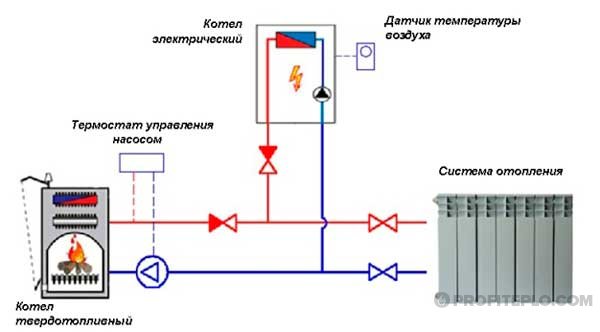 Scheme of connection of solid fuel boiler and electric boiler
Boiler units are connected in parallel with the installation of check valves at each outlet. The electric boiler is equipped with a built-in circulation pump, which cannot be turned off, therefore, for a solid fuel heat generator, it is necessary to select a more powerful pump so that the TT boiler has an advantage over an electric one when operating together.
- a thermostat that turns off the circulation pump TT of the boiler when the coolant cools down;
- a room temperature sensor that turns on the electric boiler when the room temperature drops after the fuel burns out in the TT unit.
Method of primary and secondary rings
How to connect two boilers in one system using a minimum amount of electronics? The use of the method of primary and secondary circulation rings allows you to perform a joint piping of the CT of the unit and the electric boiler. Hydraulic flow separation is carried out without the installation of a hydraulic switch.
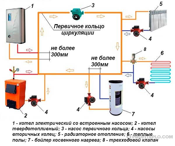 Option to connect two types of boilers to one heating system
Both boilers, the DHW boiler, as well as all heating circuits, are connected by both the supply and return pipelines to a single circulation ring - they are primary. The minimum pressure difference is ensured due to the small distance between each pair of connections (no more than 300 mm). The pressure of the pump installed on the main circuit ensures the movement of the coolant along the primary ring, while the flow rate is not affected by the pumps of the secondary circuits (to which heat consumers are connected).
For the system to function properly, it is necessary to perform complex hydraulic calculations and select the optimal diameter of pipelines for all circuits.
It is also important to calculate the performance of the pumps. The actual performance of the pumping unit on the main circuit must exceed the flow rate of the coolant on the most "volumetric" secondary circuit
Both boilers are equipped with shut-off thermostats so that they can work replacing each other.