Stage one
This includes an aerodynamic calculation of mechanical air conditioning or ventilation systems, which includes a number of sequential operations. A perspective diagram is drawn up, which includes ventilation: both supply and exhaust, and is prepared for calculation.

The dimensions of the cross-sectional area of the air ducts are determined depending on their type: round or rectangular.
Schema formation
The scheme is drawn up in axonometry with a scale of 1:100. It indicates the points with located ventilation devices and the consumption of air passing through them.
When building a highway, you should pay attention to which system is being designed: supply or exhaust
Supply
Here the calculation line is built from the most remote air distributor with the highest consumption. It passes through supply elements such as air ducts and ventilation unit up to the place where the air is taken. If the system must serve several floors, then the air distributor is located on the last one.
exhaust
A line is built from the most remote exhaust device, which consumes the air flow to the maximum, through the main line to the installation of the hood and further to the shaft through which air is released.
If ventilation is planned for several levels and the installation of the hood is located on the roof or attic, then the calculation line should begin with the air distribution device of the lowest floor or basement, which is also included in the system. If the hood installation is located in the basement, then from the air distribution device of the last floor.
The entire calculation line is divided into segments, each of them is a section of the duct with the following characteristics:
- air duct of the same section size;
- from one material;
- with constant air consumption.
The next step is the numbering of the segments. It starts with the most distant exhaust device or air distributor, each is assigned a separate number. The main direction - the highway is highlighted with a thick line.
Further, on the basis of the axonometric scheme for each segment, its length is determined, taking into account the scale and air consumption. The latter is the sum of all the values of the consumed air flow flowing through the branches that are adjacent to the highway. The value of the indicator, which is obtained as a result of sequential summation, should gradually increase.
Determination of dimensional values of air duct sections
It is made on the basis of such indicators as:
- air consumption in the segment;
- normative recommended values for the speed of air flow are: on highways - 6 m / s, in mines where air is taken in - 5 m / s.
The preliminary dimensional value of the duct is calculated on the segment, which is reduced to the nearest standard. If a rectangular duct is selected, then the values are selected based on the dimensions of the sides, the ratio between which is not more than 1 to 3.
Initial data for calculations
When the scheme of the ventilation system is known, the dimensions of all air ducts are selected and additional equipment is determined, the scheme is depicted in a frontal isometric projection, that is, axonometry. If it is performed in accordance with current standards, then all the information necessary for the calculation will be visible on the drawings (or sketches).
- With the help of floor plans, you can determine the length of the horizontal sections of air ducts. If on the axonometric diagram there are marks of the heights at which the channels pass, then the length of the horizontal sections will also become known.Otherwise, sections of the building with laid air duct routes will be required. And in the extreme case, when there is not enough information, these lengths will have to be determined using measurements at the installation site.
- The diagram should show with the help of symbols all additional equipment installed in the channels. These can be diaphragms, motorized dampers, fire dampers, as well as devices for distributing or extracting air (grilles, panels, umbrellas, diffusers). Each unit of this equipment creates resistance in the path of the air flow, which must be taken into account in the calculation.
- In accordance with the regulations on the diagram, near the conditional images of the air ducts, the air flow rates and the dimensions of the channels should be affixed. These are the defining parameters for calculations.
- All shaped and branching elements must also be reflected in the diagram.
If such a scheme does not exist on paper or in electronic form, then you will have to draw it at least in a draft version, you cannot do without it in calculations.
2. Calculation of friction losses
Losses
flow energies are calculated proportionally
so-called
"dynamic" head, magnitude
pW2/2,
where p is the density
air at flow temperature
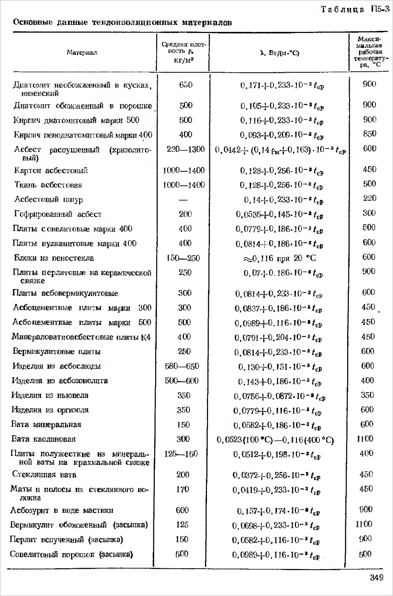
(determined according to table (1)
and (2)), a
W
- speed in a particular section of the contour
air circulation.
The fall
air pressure due to the action
friction calculate
according to the Weisbach formula:
 =
=

wherel
— length of the section of the circulation circuit, m,
deq-equivalent
section cross section diameter,
m,
deqv=
 -coefficient
friction resistance.
Coefficient
 resistance
friction is determined by the air flow regime
in the considered section of the contour
circulation, or the value
Reynolds criterion:
Re= deq
deq
where
Wideq
- speed and equivalent diameter
channel
and
kinematic viscosity coefficient
air (determined according to the tables
/1/ and /2/,
m
/With.
Meaning
 for valuesRev
interval 105
-108
(developed
turbulent
value) is determined by the formula
Nikuradze:
 =3,2
=3,2
.
10-3—
0,231 .Re-0,231
More
selection details
 can be obtained from /4/ and /5/ B
/5/
a diagram for finding
values
 ,
,
facilitating
calculations.
Computed values
 expressed in pascals (Pa).
V
table 3 summarizes the values of the initial
data for each channel
speed,
length, cross section,
equivalent diameter,
magnitude
Reynolds criterion, coefficient
resistance,
dynamic
head and the value of the calculated losses on
friction.
|
Table 3 |
||||||||
|
channel number |
W, m/s |
F, m2 |
deq M |
l, |
|
Re |
|
|
|
1 |
15 |
0.8 |
0,77 |
1,0 |
76,5 |
3,5 |
0,015 |
1,5 |
|
2 |
25 |
0,87 |
0,88 |
1,75 |
212,5 |
6,7 |
0,013 |
5,5 |
|
3 |
21,7 |
1,0 |
0,60 |
3,0 |
160,1 |
3,9 |
0,014 |
11,2 |
|
4 |
28,9 |
0,75 |
0,60 |
1,75 |
283,9 |
5,3 |
0,0135 |
11,2 |
 W2/2
W2/2
 ,
,
Calculations
friction resistance in the furnace channels
5.3.
"Local" losses
- this term refers to losses
energy in those
places where the air flow suddenly
expands or narrows, undergoes
turns, etc.
V
there are enough such places for the designed furnace
many - heaters, turns
channels, expanding or narrowing channels
and etc.
These
losses are calculated in the same way as the share
dynamic head p=W2/2,
multiplying
it on the so-called "coefficient
local resistance"
 :
:
Sum
 29.4Pa
 local
local
= /2
/2
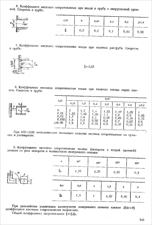
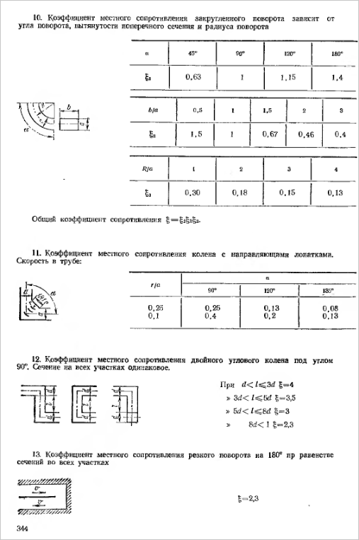
Coefficient
local resistance is determined
but tables /1/ and /5/ depending on the type
local resistance, and overall
characteristics. For example, in
this furnace local resistance type
sudden narrowing takes place
in channel 1-2 (see Fig. 7). Section ratio
(narrow to wide). By
application /1 / find
 =0,25
=0,25

= 160Pa,
Absolutely
other local
losses. Necessary
note that in some cases local
losses are due
the action of two types of resistance at once.
For example, has
place the channel turn and at the same time
change in its cross section (narrowing
or extension) should be carried out
loss calculation for
both cases and add up the results.
Results of Local Loss Calculations
summarized in table 4
|
№ |
A type |
W, m/s |
|
|
Note. |
|
sudden |
43,4 |
0,125 |
160 |
Nah. according to the table |
|
|
1-1 |
Turn |
25 |
1,5 |
318 |
~ |
|
2-3 |
rounded |
25 |
O,1 |
21,3 |
~ |
|
3 |
Aperture in
stream |
35,8 |
3,6 |
601 |
~ |
|
3-4 |
rounded |
21,7 |
0,28 |
44,8 |
~ |
|
4-1 |
Turn |
28,9 |
0,85 |
241 |
~ |
|
4-1 |
sudden |
28,9 |
0,09 |
25,5 |
~ |

 Pa
Pa
Sum
 =1411.6 Pa
Total
losses:
 =30 + 1410 =1440 Pa
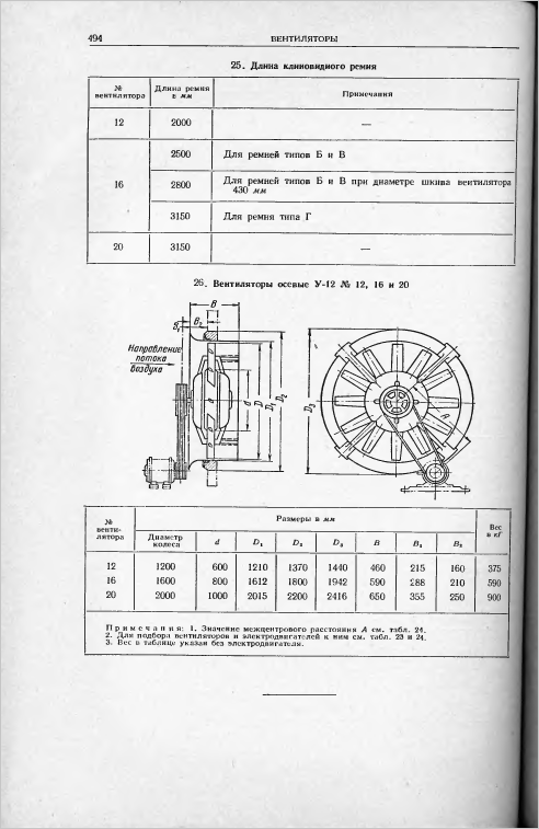
Fans
choose according to features
centrifugal
fans
, presumably for VRS type No. 10
(working
wheel
diameter 1000
mm).
For
performance 21,5
m3/With
and the required pressure H>1440
Pa..
We get: n=550
rpm;
 ,5;
,5;
Nmouth
 25
25
kW.
Drive unit
fan from asynchronous motor,
power 30
kW
type
JSC
at 720
rpm,
through a V-belt drive.


Stage two
Here, aerodynamic drag indicators are calculated. After choosing the standard sections of the air ducts, the value of the air flow velocity in the system is specified.
Friction Pressure Loss Calculation
The next step is to determine the specific friction pressure loss based on tabular data or nomograms. In some cases, a calculator can be useful to determine indicators based on a formula that allows you to calculate with an error of 0.5 percent. To calculate the total value of the indicator characterizing the pressure loss in the entire section, you need to multiply its specific indicator by the length. At this stage, a correction factor for roughness should also be taken into account. It depends on the magnitude of the absolute roughness of a particular duct material, as well as the speed.
Calculation of the dynamic pressure index on the segment
Here, an indicator characterizing the dynamic pressure in each section is determined based on the values:
- air flow rate in the system;
- air mass density under standard conditions, which is 1.2 kg/m3.
Determination of local resistance values in sections
They can be calculated from local resistance coefficients. The obtained values are summarized in a tabular form, which includes data from all sections, and not only straight segments, but also several shaped parts. The name of each element is entered in the table, the corresponding values \u200b\u200band characteristics are also indicated there, by which the coefficient of local resistance is determined. These indicators can be found in the relevant reference materials for the selection of equipment for ventilation installations.

In the presence of a large number of elements in the system or in the absence of certain values of the coefficients, a program is used that allows you to quickly carry out cumbersome operations and optimize the calculation as a whole. The total resistance value is defined as the sum of the coefficients of all segment elements.
Calculation of pressure losses on local resistances
Having calculated the final total value of the indicator, they proceed to the calculation of pressure losses in the analyzed areas. After calculating all segments of the main line, the obtained numbers are summed up and the total resistance value of the ventilation system is determined.
Calculation of air ducts for supply and exhaust systems of mechanical and natural ventilation
Aerodynamic
calculation of air ducts is usually reduced
to determine the dimensions of their transverse
section,
as well as pressure losses on individual
plots
and in the system as a whole. Can be determined
costs
air for given dimensions of air ducts
and known differential pressure in the system.
At
aerodynamic calculation of air ducts
ventilation systems are usually neglected
compressibility
moving air and enjoy
overpressure values, assuming
for a conditional
zero atmospheric pressure.
At
movement of air through the duct in any
transverse
flow cross section there are three types
pressure:
static,
dynamic
and complete.
static
pressure
determines the potential
energy 1 m3
air in the section under consideration (pst
equal to the pressure on the walls of the duct).
dynamic
pressure
is the kinetic energy of the flow,
related to 1 m3
air, determined
according to the formula:
(1)
where
– density
air, kg/m3;
- speed
air movement in the section, m/s.
Complete
pressure
equal to the sum of static and dynamic
pressure.
(2)
Traditionally
when calculating the duct network, it is used
the term "loss
pressure”
("losses
flow energy”).
Losses
pressure (full) in the ventilation system
are made up of friction losses and
losses in local
resistances (see: Heating and
ventilation, part 2.1 “Ventilation”
ed. V.N. Bogoslovsky, M., 1976).
Losses
friction pressures are determined by
formula
Darcy:
(3)
where
- coefficient
friction resistance, which
calculated by the universal formula
HELL. Altshulya:
(4)
where
– Reynolds criterion; K - height
roughness projections (absolute
roughness).
engineering pressure loss calculations
friction
,
Pa (kg/m2),
in an air duct with a length /, m, are determined
by expression
(5)
where
– losses
pressure per 1 mm of duct length,
Pa/m [kg/(m2
* m)].
For
definitions Rdrawn up
tables and nomograms. Nomograms (Fig.
1 and 2) are built for the conditions: section shape
duct circle diameter,
air pressure 98 kPa (1 atm), temperature
20°C, roughness = 0.1 mm.
For
calculation of air ducts and channels
rectangular sections are used
tables and nomograms
for round ducts, introducing at
this
equivalent diameter of a rectangular
duct, in which the pressure loss
for friction in
round
and rectangular
~
air ducts are equal.
V
design practice received
Spread
three types of equivalent diameters:
■ by speed
at
parity of speeds
■ by
consumption
at
cost equity
■ by
cross-sectional area
if equal
cross-sectional areas
At
calculation of air ducts with roughness
walls,
different from that provided for in
tables or nomograms (K = OD mm),
make a correction to
tabular value of specific losses
pressure on
friction:
(6)
where
- tabular
specific pressure loss value
for friction;
- coefficient
taking into account the roughness of the walls (Table 8.6).
Losses
pressure in local resistances. V
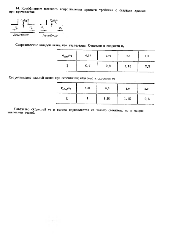
places of rotation of the duct, when dividing
and merger
flows in tees, when changing
sizes
air duct (expansion - in the diffuser,
constriction - in the confuser), at the entrance to
air duct or
canal and exit from it, as well as in places
installations
control devices (throttles,
gates, diaphragms) there is a drop
flow pressure
moving air. In the specified
places going on
restructuring of air velocity fields in
air duct and the formation of vortex zones
at the walls, which is accompanied
loss of flow energy. alignment
flow occurs at some distance
after passing
these places. Conditionally, for convenience
aerodynamic calculation, loss
pressure in local
resistances are considered concentrated.
Losses
pressure in local resistance
determined
according to the formula
(7)
where
–
local resistance coefficient
(usually,
in some cases there is
negative value, when calculating
should
take into account the sign).


Ratio refers to
to top speed
in the narrow section of the section or speed
in section
section with a lower flow rate (in a tee).
In tables
local resistance coefficients
indicates which speed it refers to.
Losses
pressure in local resistances
plot, z,
calculated by the formula
(8)
where
- sum
local resistance coefficients
Location on.
Are common
pressure loss in the duct section
length,
m, in the presence of local resistances:
(9)
where
– losses
pressure per 1 m of duct length;
– losses
pressure in local resistances
site.