3.3. Electrical control circuit
circulation
pumps
Circulating
pumps are installed in the central heating station for hot
water supply. They support
desired water temperature and pressure
at water points.
For
For example, consider an electrical circuit
circulation pump control
(Fig. 2.23), installed at the central heating station for
hot water circulation circuit system
heat consumption (see Fig. 3.1-3.3).
Principle
circuit work.
Before switching on the pumps, apply
voltage in the power circuit and circuit
control of pumping units
circuit breakers QF1,
QF2
and SF.
The choice of the working pump is carried out
switch SA.
When choosing a working pump NC1
switch
SA
set in position I.
Relay coil energized
management K1,
which is triggered by its closing
contact K1
(1-13)serves
magnetic coil voltage
starter KM1.
The magnetic starter works and
with its power contacts
KM1 includes
electric motor M1
pump NC1.
At the same time block contact KM1(1-21)served
signal lamp voltage HL1
"Normal
pump operation NC1».
Rice.
2.23. Circuit diagram
management
circulation
pumps
E if
if
for some reason the pump stoppedNC1,
then the differential pressure switch is activated.
SP
and its closing contact SP
(1-25) energizes the relay coil
time CT,
which, with a time delay, closes
your contact CT
(1-27) and energizes the relay KA
to trigger
automatic switching on of the reserve
(ATS), which provides automatic
switching on the backup pump NC2.
It happens in the following way. Relay
KA
triggered by its NC contact
KA (3-5)
removes voltage from the relay coil
management K1,
and closing contact KA
(3-7) energizes the coil
intermediate relay K2.
Relay K2
also triggered by closing contact K2
(1-17) energizes the coil
magnetic starter KM2,
which by power contacts KM2
turns on the electric motor
M2
pump NC2.
At the same time, the warning light comes on.
lamp HL2
"Normal operation of the pump NC2»,
loud ringing bell is turned on ON THE
and the warning light comes on HL3
«AVR
enabled." NO contact KA
(1-27) NO contact is bridged CT.
The alarm can be turned off by pressing
on the control button SB
(27-29).
At
choosing a working pump NC2
switch SA
set in position II.
Then the pump will work NC2,
a standby pump NC1.
V
the scheme provides for all types of protection
power circuit and control circuit.
Maximum protection is provided
circuit breakers QF1,
QF2
and SF,
thermal overload protection
releases of circuit breakers
QF1,
QF2
and electrothermal relays KK1
and KK2.,
zero protection by magnetic starters
KM1 and
KM2.
Timer to control the pump Meander entertaining electronics
The device, the circuit of which is shown in the figure, periodically generates pulses of positive polarity at the output (at pin 11 of the DD1 microcircuit). It contains two IC generators working in turn (on elements DD1.1 and DD1.2), a switch on element DD1.3, a serial circuit of four counters of microcircuits DD2, DDZ, an inverter on element DD1.4 and an electronic relay on a transistor VT1 and electromagnetic relay K2, which controls the operation of the magnetic starter K1. Pulse duration (Ton) and pauses between them (Toff) depends on the frequency generated by the pulse generators and used counter outputs and can be adjusted over a wide range.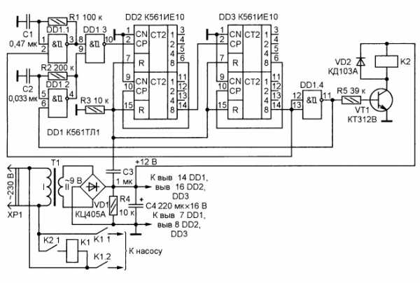
With the device connected to the network, a constant supply voltage appears at the output of the rectifier VD1, and thanks to the R3C3 circuit, the counters of the microcircuits DD2, DD3 are set to zero. In this case, the log level appears at the output of the inverter DD1.4. 1 and the generator on the element DD1.2 is included in the work.At the same time, transistor VT1 opens, relay K2 is activated and, with its contacts K2.1, connects the winding of the magnetic starter K1 to the network, as a result of which it also works and contacts K1.1, K1.2 connects the load to the network. From the output of the DD1.3 element, pulses with a repetition rate of this generator are fed to the CN input (pin 2) of the first counter of the DD2 microcircuit. The countdown begins Ton.
With the advent of the logo. 1 at the output of the counter (pin 14 DD3) log level. 1 at the output of the element DD1.4 is replaced by the log level. 0, the transistor VT1 closes, de-energizing the relay K2, it releases and breaks the power circuit of the magnetic starter K1, which, in turn, turns off the load. At the same time, the generator on the DD1.1 element is turned on, pulses with the frequency of this generator begin to arrive at the CN input of the first counter of the DD2 microcircuit - the time T beginsoff at the end of which everything repeats from the beginning.
In practice, the device has been used for the fourth year to control a water pump with a capacity of 2500 l / h, pumping water from a well with a flow rate of 300 l / h, according to a given cycle. For the ratings of the elements R1, R2, C1 and C2 indicated in the diagram, the pump is turned on for a time Ton \u003d 151 s \u003d 2 min 31 s, pumps out about 130 liters of water into the storage tank, and then turns off for a time Toff = 27 min, during which water accumulates in the well. The need to control the pump with such a cycle is due to the fact that without washing with water, the pump fails. The device is powered by an unstabilized source containing a step-down transformer T1 with a secondary winding of 9 V and a KTs405A rectifier bridge. To control the starter K1, a relay K2 was used with a winding with a resistance of about 700 ohms and a rated voltage of 12 V.
What is well automation
The automation unit for submersible or surface pumps is a modern electronics that includes a hydraulic accumulator, modules and a pressure gauge. All of them guarantee the correct operation of the highway.
Functions of automation for water pumps:
- Control. All processes are carried out in an automated mode, without control and supervision.
- Water hammer protection. A water supply is created in the highway in case of equipment malfunction and breakdown.
- Electronic devices are triggered in the absence of a liquid medium, turning off the electric current.
Automation for a water supply pump without a hydraulic accumulator helps prevent equipment breakdown, its premature failure.
Well automation device.
What can an automatic time relay
17.12.2013
Time relay (timer) - provide automatic switching on / off of industrial or household appliances according to a pre-set program.
They are used in a variety of areas: from turning on the heater in the apartment for your arrival, organizing automatic watering of the site when you are away, to controlling the switching on and off of engines and automatic machines in production.
Automatic inclusion of heating.
You can program the heater to turn on at a certain time so that the room or house is already warm when you arrive. Also, in the absence of a weekly timer on the thermostat of your warm floor, floor heating can be programmed using a timer, and then the floor will already be warm by the time you arrive or wake up.
Automatic shutdown of electrical appliances.
For example, you want to limit your child's TV viewing time, or limit the time they spend on the computer. You just need to connect your TV/computer via a time relay and program the time to turn off.
Automatic control in the suburban area.
You can automatically turn on and off the lighting in the area. Using the time relay, you can program the on / off irrigation of the site.For example, watering should be turned on every 12 hours for 15 minutes, the relay is programmed to turn on after 11 hours and 45 minutes and turn off 15 minutes after turning on. Then we program the constant repetition of this cycle.
Automatic control of the electric pump.
One of the options for using the time relay is to install it on electric pumps. If the well is small, then to fill the tank with water, you have to turn the pump on and off several times, that is, practically do not move away from it until the tank is full. If the pump quickly sucks water out of the well and continues to work, then it overheats and may fail, as the water pump is cooled by water. To automate the process of filling the reservoir with water, it is necessary to experimentally determine how long the water is pumped out of the well by the pump (for example, 2 minutes), how long it takes to fill the well (for example, 15 minutes) and how many times the pump needs to be turned on in order for the reservoir to be filled ( e.g. 8 times). After all the measurements taken, we simply program the relay according to the following scheme: turn on for 2 minutes, turn off for 15 minutes and repeat this cycle 8 times. Now you can just turn on the pump and go about your business.
Automation of signboards and outdoor advertising.
It is not economically feasible for a sign to be permanently lit. But it's so inconvenient not to forget to turn it off in the evening, and then not to forget to turn it on in the morning. And this process can be simply automated with the help of a time relay. Thus, you simply program the relay once and forget about the human factor when saving on electricity.
Using a time relay in production.
The time relay, as well as in everyday life, can be used in various areas of production. Lighting automation. Automation of switching on / off engines and equipment.
Thus, there are a lot of scopes for time relays, this list goes on and on. If you need to automate the process of turning on / off a device, you can always consult a specialist, and he will always tell you how to do it and which device to use for this.
Pump control circuit
Category: Consumer electronics
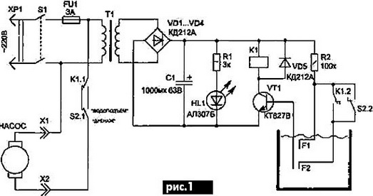
This device can be useful in a country house or a farm, as well as in many other cases when it is necessary to control and maintain a certain level of water in the tank.
So, when using a submersible pump to pump water from a well for irrigation, you need to make sure that the water level does not drop below the position of the pump. Otherwise, the pump, idling (without water), will overheat and fail.
 TO ENLARGE (REDUCE) THE SCHEME, CLICK ON THE PICTURE
The scheme of the universal automatic device (Fig. 1) will help you get rid of all these problems. It is simple and reliable, and also provides for the possibility of multifunctional use (water lifting or drainage).
The circuit circuits are not connected in any way with the tank body, which excludes electrochemical corrosion of the tank surface, unlike many previously published circuits of a similar purpose.
The principle of operation of the circuit is based on the use of the electrical conductivity of water, which, falling between the plates of the sensors, closes the circuit of the base current of the transistor VT1. In this case, relay K1 is activated and with its contacts K1.1 turns on or off (depending on position 82) the pump.
TO ENLARGE (REDUCE) THE SCHEME, CLICK ON THE PICTURE
Similar schemes:
PUMP CONTROL ASSEMBLY
Consumer electronics PUMP CONTROL UNIT To periodically fill the tank or, conversely, remove liquid from it, you can use a device, the schematic diagram of which is shown in fig.
1 and the design in Fig.
2. The use of reed sensors in it has some advantages - there is no electrical contact between the liquid and the electronic unit, which allows it to be used for pumping out condensation water, a mixture of water with oils, etc.
In addition, the use of these sensors
Chips K174KN1, K174KN2
Reference materials Microcircuits K174KN1, K174KN2 K174KN1 Designed to work in the program selection unit of television receivers with electronic channel selectors as an eight-channel voltage switch.
Housing type 238.16-2 Weight of the microcircuit, not more than 1.5 g Functional diagram DD1, DD2, DDZ - logic circuit o - inversion & - multiplier of the "AND" function Pin assignment 1 Blocking input APCG 2 Output 1 channel 3 .
Common output 4,5,6 Output 3,
DIGITAL VOLTMETER ON CHIP C520
Measuring equipment DIGITAL VOLTMETER ON THE C520D CHIP (produced in the GDR) Schematic diagram of the voltmeter Printed circuit board Variants of the input circuit Switching on LED indicators with a common cathode As decoders, you can use, for example, K514ID1, K514ID2.
It is also possible to use K155ID1 if ten-day indicators are used.
Transistors - type KT361 or similar other p-n-p conductivity.
The original RF generator modulation scheme
Radio spy The original modulation scheme of the HF generator The originality of the idea lies in the fact that the varicap matrix modulator VD1, VD2 is included in the output circuit of the generator, which greatly simplifies the management circuit, does not require an AF amplifier for the microphone (like "pine").
Output circuit Tuned to the second harmonic of the resonator - at 140 MHz.
When repeating the circuit, it is necessary to select R4 to establish a frequency deviation of 3 kHz.
Miniature transmitter (*)
Radio Spy Miniature Transmitter Schematic Diagram Printed Circuit Board
Ham radio machine
Ham Radio Technology Ham Radio Machine Plotter Drilling Machine ….? Universal set of elements The movement of structural elements is carried out using stepper motors (those used in 5-inch drives).
Their management is carried out from a small circuit through the parallel port of a personal computer.
P.S.
Judging by the drawings, this is not such a complicated device, and some factory could fully master its production from
leave a comment
Time relay for turning on the pump as an integral element of the automation system
 Time relayBuy from 1875 р.
A time relay is a special electrical device with which you can control the operation of a pump and other electrical equipment. The device is able to close / open el. circuit and form time intervals for turning on / off electrical devices. Due to this, a certain sequence (algorithm) of the work of the elements of email is provided. scheme. Thus, the relay creates a time delay and automatically controls such technological processes as: irrigation, heating, water supply, air conditioning, etc.
For example, in a heating system with pump circulation, using a relay, it is possible to organize the operation of the pump so that it turns on with a certain time delay, and the heating elements of the electric heating boiler would have time to warm up. Thus, the stability and uninterrupted operation of important production and technological processes depend on the reliability of the time relay.
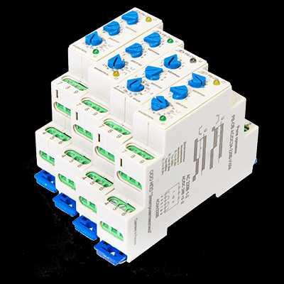
We present to your attention professional devices for automating the operation of the electric pump of the Russian manufacturer NPO Elektroavtomatika - a time relay. Electromechanical devices contain several operation algorithms with wide time intervals and supply voltage tolerances, due to which they demonstrate high quality characteristics in each case of operation.
We produce 2 types of relays:
- time relay to turn off RV-OO for the control of el. circuits after removing the supply voltage;
- time relay for switching on RV-OV to control el. circuits after the supply voltage is applied.
We will tell you why the relay is an excellent choice for a water supply system. With the help of our devices, you will be able to simultaneously control 2 independent electrical circuits - 2 switching groups of contacts. That is, you can connect 2 different devices and supply different power to them. The principle of operation of the functional device is that the relay does not turn on the pump immediately after the supply voltage is applied, but after a certain time.
Types of time relay
The time relay with a delay to turn off - RV-OV is widely used to control a pump or pumping station. The device allows you to fill the hydraulic tank in automatic mode, adjusting the on and off of the pump. Contains two operation diagrams and five time delay ranges: 0.1 s; 1 s; 0.1 m; 1m; 0.1 h. So, for each operation diagram, you can specify one of three time intervals and set a time delay for the relay to operate after power is applied.
Advantages of the NPO Elektroavtomatika time relay:
- Reliable specifications.
- Switching of heavy loads: with a resistive load - 5 A AC.
- Efficiency. Control of two independent electrical circuits - two switching groups of contacts.
- Easy installation. Mounting on DIN rail 35 mm wide.
The second type of time relay to turn off - RV-OO turns on immediately when the supply voltage is applied, and turns off after a certain time delay after turning off the power. The device contains four operation diagrams and three time delay ranges: 0.1 s; 1s; 0.1min In practice, the RV-OO relay allows you to organize an effective automated process control system both in production and in the household.
If you were looking for a reliable device for automating the operation of such equipment as: an engine or a pump, and also want to organize a system for turning on and off electrical appliances, then the NPO Elektroavtomatika time relay will suit you. For more than 10 years, our devices have been in demand in automation systems. When ordering, you can specify the required operation diagram, exposure time range, supply voltage and other characteristics.
Buy a time relay to turn on the pump
On our website you can order a functional time relay to turn on the pump. In addition, in our catalog you will find a comprehensive range of electrical products adapted to your requirements: from basic solutions to manufacturing according to the customer's project and translating your ideas into the finished product.
We invite you to cooperate with our manufacturing company and offer to order reliable electrical products at attractive prices. In the face of NPO Elektroavtomatika, you will find a direct supplier and will be able to order the necessary electrical devices and components with delivery to any region of Russia.
Two simple options for turning off the water pump
The scheme of the automatic device is quite simple if a float-based water level sensor is used (Fig. 1). If the container where water is drawn is not filled, then the contacts of the float sensor are open.
Now, if you press the SB1 button, the supply voltage will start the pump and turn on the electromagnetic relay K1 in parallel with the voltage coming through the capacitance and the diode bridge VD1. As a result, the relay with its contacts K1.1 shunts the outputs of the button SB1. Now, if the container is filled with water, then the contacts of the float sensor are closed by the contacts SA1, which in turn will turn off the relay and the pump motor. To resume the process, press the SB1 button again.
Capacitor C1 - quenching, necessary to reduce the voltage supplied to the relay, resistance R1 reduces the discharge current of the capacitor capacitance when the SA1 sensor contacts are shorted. This automatic device uses an electromagnetic relay of the RPU-2 type with a winding resistance of 4.5 kOhm and a rated voltage of 110 V. The SB 1 button must withstand the current consumed by the electric pump. Capacitance C1 must be for a voltage of more than 400 V (K73-16, K73-17). Rectifier bridge VD1 - for a voltage of more than 300 V.
Attention! Since the circuit is not electrically isolated from the mains, extreme care must be taken when working with this circuit. But still, a float-based sensor is not entirely convenient (not safe), since the sensor contacts are directly connected to circuit elements that are energized at 220 volts. Below (Fig. 2) is a schematic diagram of an automatic device with a sensor built on a non-contact basis
2) shows a schematic diagram of an automatic device with a sensor built on a non-contact basis
But still, a float-based sensor is not entirely convenient (not safe), since the sensor contacts are directly connected to circuit elements that are energized at 220 volts. Below (Fig. 2) is a schematic diagram of an automatic device with a sensor built on a non-contact basis.
At the moment of closing the SA1 contacts, the supply voltage is supplied to the circuit of the machine. If the storage tank is not completely filled, then in this case the transistor VT1 is locked. The rectified voltage (about 30 volts) after the diode bridge, through the circuit of elements R5, C2, goes to the electromagnetic relay K1, which is activated at the moment SA1 is pressed and its contacts connect the pump to the mains.
Further, the capacitance C2 is gradually charged, as a result of which the current flowing through the winding of the electric relay K1 decreases. But the relay does not turn off, because for its operation there is enough current flowing through the resistance R4. The glow of the HL1 LED indicates that the pump is on and water is being drawn.
When filling the container with water, as soon as the water touches the contacts 1 and 2 of the sensor, the transistor VT1 will open. Its collector current turns off the electromagnetic relay and turns on the HL2 LED, which indicates that the tank is full. The relay outputs K1.1 and K1.2 of the relay break the power supply circuit of the pump and the pump stops.
When the water level decreases, the sensor contacts are dried and thereby turn off the transistor, the HL2 LED goes out, but the pump does not resume, since there is not enough current flowing through the resistance R4. To start the pump again, press the SA1 button again.
Capacitance C1 reduces noise in the wires connecting the circuit to the sensor contacts. Resistance R5 reduces the recharging current of capacitance C2 passing through the transistor VT1 during its opening. A voltage divider is built on the resistances R1 and R2, which determines the potential at the sensor contacts and fixes the value of the base current VT1.
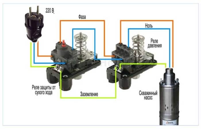
Characteristics of the pump dry-running protection relay
The dry running sensor for the pump refers to electromechanical type devices that control whether there is pressure in the system through which water is transported. If the pressure level is below the regulatory threshold, such a relay automatically stops the operation of the pumping equipment, opening the circuit of its electrical power.
The dry running relay for the pump consists of:
- membrane, which is one of the walls of the inner chamber of the sensor;
- a contact group that provides closing and opening of the circuit through which electric current flows to the pump motor;
- springs (the degree of its compression regulates the pressure at which the relay will operate).
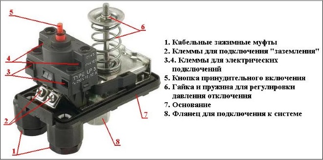
The main elements of the "dry run" relay
The principle by which such a dry-running protection relay works is as follows.
- Under the pressure of the water flow in the system, if its level corresponds to the standard value, the membrane of the device bends, acts on the contacts and closes them. Electric current in this case is supplied to the pump motor, and the latter operates normally.
- If there is not enough water pressure or it does not enter the system at all, the membrane returns to its original state, opening the electric power supply circuit of the pumping unit and, accordingly, turning it off.
Situations when the fluid pressure in water supply systems drops sharply (which means that the pump needs protection from dry running) are caused by various reasons. Among such reasons are depletion of the natural water source, clogged filters, too high location of the self-priming part of the system, etc.
Pump dry running protection relays are usually installed on the surface of the earth, in a dry place, although there are models made in a moisture-proof housing that can be mounted with pumping equipment in the well.
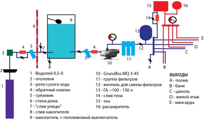
An example of automatic water supply for a residential building
The relays that prevent the dry running of the pump work more effectively when they are installed in systems that are not equipped with a hydraulic accumulator that are served by a surface circulation pump. Of course, it is possible to install such a relay in a system with a hydraulic accumulator, but in this case it will not be able to provide one hundred percent protection of the pumping unit from dry running. In this case, the relay connection diagram looks like this: it is placed in front of the water pressure sensor and the hydraulic accumulator, and immediately after the pumping station, a check valve is installed that prevents the water from moving in the opposite direction. With this connection, the dry-running relay membrane is constantly under water pressure created by the accumulator. This can lead to the fact that the pump, which will not receive water from the source, simply does not turn off.