Calculation of a steam boiler
The steam capacity of the boiler room is equal to:
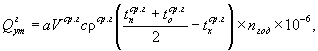
DK=DP+DSP+ DSN-GROU1-GROU2, kg/s
Steam consumption for fuel oil facilities DMX = 0.03DP = 0.03•2.78= 0.083 kg/s
Let us determine the steam consumption for network heaters.
Let's determine the temperature of the return network water at the entrance to the boiler room:
h - efficiency of the DHW heater at the central heating station 0.98 (98%).
Let us determine the enthalpy of the heating steam condensate after the cooler:
Dt - undercooling condensate up to t return network water in the cooler.
Saturation temperature in the network heater:
We determine the enthalpy in the network heater according to tNAS
\u003d 2738.5 kJ / kg
Steam consumption for the network heater
ZSP - efficiency of the network heater 0.98
Determine the flow rate of blowdown water for steam boilers
where K • DP - expresses the steam consumption for own needs K - 0.08 - 0.15
-percentage of boiler blowdown
- steam capacity of the boiler room
Let's find the consumption of purge water going to the sewer
Enthalpy of blowdown water from the boiler drum (according to P in the boiler drum)_
enthalpy of steam and boiling water at the outlet of the SNP (according to P = 0.12 MPa in the deaerator)
Consumption of secondary steam from SNP going to the feed deaerator
We determine the consumption of tap water at the entrance to the boiler room to make up for losses
Here - no return of condensate from production; loss of water in heating networks; loss of condensate and water inside the boiler house.
water leaving the continuous blowdown of the boiler into the sewer
Temperature of tap water after cooling
Here tcool \u003d 50 0С is the temperature of the water removed to the sewer
cold water temperature
coefficient cooler heat loss
— water temperature leaving the continuous blowdown separator
Steam consumption for tap water heaters
water temperature downstream of the heater in front of cold water = 300C
tN is the saturation temperature in the deaerator (by pressure in the deaerator 0.12 MPa);
id”, id’ is the enthalpy of steam and condensate (by pressure in the deaerator 0.12 MPa).
Steam consumption for make-up water deaerator
CWW consumption at the inlet to the make-up water deaerator:
Make-up water temperature after cooler
Here, tHOV = 27 0C is the temperature of the cold water after the cold water;
Steam consumption for the CWW heater entering the feed water deaerator:
Here GHOB2 is the flow rate of COW at the inlet to the feed deaerator:
Here tК = 950С is the temperature of condensate from production and fuel oil facilities.
Feed deaerator capacity:
Adjusted expenses for own needs:
DCH = Dd1+ Dd2+ DП1+ DП2+ DМХ = 0.068+0.03+0.12+0.15+0.08 = 17.97 kg/s
The flow rate of water injected into the desuperheater ROU1 upon receipt of reduced industrial steam:
Here iK” is the enthalpy of steam behind the boiler (based on the pressure in the drum);
iP” is the enthalpy of steam at industrial needs at the exit from the boiler room or at the entrance to the main
(according to P and t);
— enthalpy of feed water in front of the boiler
The flow rate of water injected into the desuperheater ROU2 when receiving steam for the boiler house's own needs:
Here iSN” is the enthalpy of reduced steam (by pressure downstream ROU2 = 0.6 MPa)
Corrected steam capacity of the boiler room:
The result is comparable to the pre-set steam output
Boiler material balance
17,97 = 17,01 + 0,84
17,95 = 17,85
Hot water transport
The calculation scheme algorithm is established by regulatory and technical documentation, state and sanitary standards and is carried out in strict accordance with the established procedure.
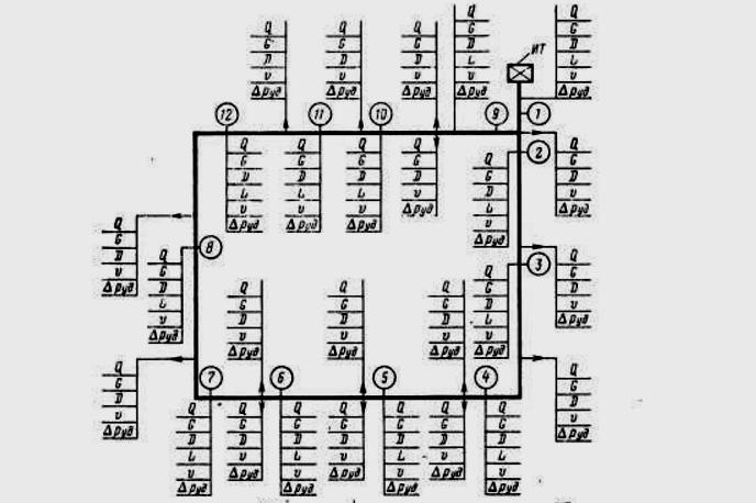
The article provides an example of the calculation of the hydraulic calculation of the heating system. The procedure is performed in the following sequence:
- On the approved heat supply scheme for the city and the district, the nodal points of calculation, the heat source, the routing of engineering systems are marked with an indication of all branches, connected consumer objects.
- Clarify the boundaries of the balance sheet ownership of consumer networks.
- Assign numbers to the site according to the scheme, starting the numbering from the source to the end consumer.
The numbering system should clearly distinguish between the types of networks: main intra-quarter, inter-house from a thermal well to boundaries of balance sheet, while the site is set as a segment of the network, enclosed by two branches.
The diagram indicates all the parameters of the hydraulic calculation of the main heat network from the central heating station:
- Q is GJ/hour;
- G m3/h;
- D - mm;
- V - m/s;
- L is the length of the section, m.
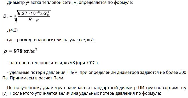
The calculation of the diameter is set by the formula.
4 Determination of normalized operational heat losses with losses of network water
2.4.1
Normalized operational heat losses with network water losses
are determined in general for the heat supply system, i.e. taking into account internal
the volume of TS pipelines, which are both on the balance sheet of the energy supply
organization, and on the balance sheet of other organizations, as well as the volume of systems
heat consumption, with the release of heat losses with losses of network water in the TS for
balance sheet of the power supply organization.
Vehicle volume per
the balance sheet of the energy supplying organization as part of AO-energo is (see.
table of real
recommendations)
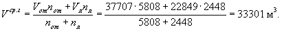
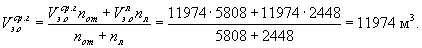
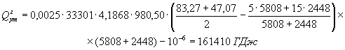
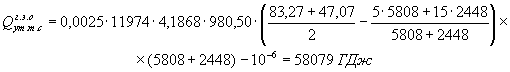
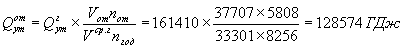
Vt.s = 11974 m3.
Vehicle volume per
balance sheet of other, mainly municipal, organizations is (according to
operational data)
Vg.t.s = 10875 m3.
Systems volume
heat consumption is (according to operational data)
Vs.t.p. = 14858 m3.
Total volumes
network water is seasonally:
- heating
season:
Vfrom = Vt.s +Vg.t.s +Vs.t.p. = 11974 + 10875
+ 14858 = 37707 m3;
- summer season
(the repair period is taken into account in the number of hours of operation of the vehicle in the summer season when determining
Vav.d):
Vl = Vt.s +Vg.t.s = 11974 + 10875 = 22849 m3.
Average annual
the volume of network water in the TS pipelines and heat consumption systems Vav.g is determined
according to the formula (37) RD
153-34.0-20.523-98 :
Including in TS
on the balance sheet of the energy supply organization
2.4.2
Normalized operational annual heat losses with normalized leakage
network water
were determined by the formula (36) RD
153-34.0-20.523-98 :
where ρaver.g is the average annual
water density, kg/m3; determined at temperature , °С;
c - specific
heat capacity of network water; is taken equal to 4.1868 kJ/(kg
× °С)
or 1 kcal/(kg × °C).
Average annual
temperature of cold water entering the source of thermal energy for
post-treatment to recharge the vehicle, (°C) is determined by
formula (38) RD
153-34.0-20.523-98 :
Temperature
cold water during the heating period is taken = 5 ° С; in summer
period = 15 °C.
Annual losses
total heat in the system
heat supply are
or
= 38552 Gcal,
including in TC
on the balance sheet of the energy supply organization
or
= 13872 Gcal.
2.4.3 Normalized
operating heat losses with normalized leakage of network water by season
operation of the vehicle - heating and summer
are determined by formulas (39) and (40) RD
153-34.0-20.523-98 :
- for
heating season
or
= 30709 Gcal,
including in TS
on the balance sheet of the energy supply organization
or
= 9759 Gcal;
- for summer
season
or
= 7843 Gcal,
including in TC
on the balance sheet of the energy supply organization
or
= 4113 Gcal.
2.4.4
Normalized operational heat losses with network water leakage by months
in heating and summer seasons
were determined by formulas (41) and (42) RD
153-34.0-20.523-98 :
- for
heating season (January)

or
= 4558 Gcal,
including in TC
on the balance sheet of the energy supply organization

or
=
1448 Gcal.
Similarly
heat losses are determined for other months, for example, for the summer season
(June):
or
= 1768 Gcal,
including in TC
on the balance sheet of the energy supply organization

or
= 927 Gcal.
Similarly
heat losses are determined for other months, the results are given in the table of these Recommendations.
2.4.5 By
the results of the calculation, plots are built (see the figure of these Recommendations) of monthly and annual heat losses from
leakage of network water in the heat supply system as a whole and on the balance sheet
energy supply organization.
The table shows the values of heat loss in
percent to the planned amount of transported thermal energy.
The low values of the ratio of heat loss to its supply are explained by the small
TS shares (according to material characteristics) on the balance sheet of the energy supply
organization compared to all networks in the heat supply system.
Choice of thermal insulation thickness
q1 - norms of heat losses, W/m;
R is the thermal resistance of the main insulation layer, K*m/W;
f is the temperature of the coolant in the pipeline, 0C;
dI, dH - outer diameter of the main insulation layer and pipeline, m;
LI - coefficient. thermal conductivity of the main insulation layer, W/m*K;
DIZ is the thickness of the main insulation layer, mm.
Steam pipeline.
Straight line: dB = 0.259 m tCP = 192 0C q1 = 90 W/m
Thermal insulation material - pierced mineral wool mats in shells, grade 150;
Return line (condensate line):
dB = 0.07 m tCP = 95 0C q1 = 50 W/m
Thermal insulation material - fiberglass mats
water lines
Plot 0-1 Direct line:
dB = 0.10m f = 150 0C q1 = 80 W/m
Thermal insulation material - fiberglass mats
Return line:
dB = 0.10 m f = 70 0C q1 = 65 W/m
Thermal insulation material - fiberglass mats
Plot 0-2 Direct line:
dB = 0.359 m f = 150 0C q1 = 135 W/m
Thermal insulation material - fiberglass mats
Return line:
dB = 0.359 m f = 70 0C q1 = 114 W/m
Thermal insulation material - fiberglass mats
Plot 0-3 Direct line:
dB = 0.359 m f = 150 0C q1 = 135 W/m
Thermal insulation material - fiberglass mats
Return line:
dB = 0.359 m f = 70 0C q1 = 114 W/m
Thermal insulation material - fiberglass mats
Indicators of normal pressure
As a rule, it is impossible to achieve the required parameters according to GOST, since various factors influence the performance indicators:
Equipment power
needed to supply the coolant. The pressure parameters in the heating system of a high-rise building are determined at heat points, where the coolant is heated for supply through pipes to radiators.
Equipment condition
. Both dynamic and static pressure in the heat supply structure are directly affected by the level of wear of boiler house elements such as heat generators and pumps.
Equally important is the distance from the house to the heat point.
The diameter of the pipelines in the apartment. If, when carrying out repairs with their own hands, the owners of the apartment installed pipes of a larger diameter than on the inlet pipeline, then the pressure parameters will decrease.
Location of a separate apartment in a high-rise building
Of course, the required pressure value is determined in accordance with the norms and requirements, but in practice it depends a lot on what floor the apartment is on and its distance from the common riser. Even when living rooms are located close to the riser, the onslaught of the coolant in the corner rooms is always lower, since there is often an extreme point of pipelines there.
The degree of wear of pipes and batteries
. When the elements of the heating system located in the apartment have served for more than a dozen years, then some reduction in equipment parameters and performance cannot be avoided. When such problems occur, it is advisable to initially replace worn pipes and radiators and then it will be possible to avoid emergency situations.
GOST and SNiP requirements
In modern multi-storey buildings, the heating system is installed based on the requirements of GOST and SNiP. The regulatory documentation specifies the temperature range that central heating must provide. This is from 20 to 22 degrees C with humidity parameters from 45 to 30%.
To achieve these indicators, it is necessary to calculate all the nuances in the operation of the system even during the development of the project. The task of a heating engineer is to ensure the minimum difference in the pressure values of the liquid circulating in the pipes between the lower and last floors of the house, thereby reducing heat loss.
The following factors influence the actual pressure value:
- The condition and capacity of the equipment supplying the coolant.
- The diameter of the pipes through which the coolant circulates in the apartment. It happens that wanting to increase the temperature indicators, the owners themselves change their diameter upwards, reducing the overall pressure value.
- The location of a particular apartment. Ideally, this should not matter, but in reality there is a dependence on the floor, and on the distance from the riser.
- The degree of wear of the pipeline and heating devices. In the presence of old batteries and pipes, one should not expect that the pressure readings will remain normal. It is better to prevent the occurrence of emergency situations by replacing your old heating equipment.
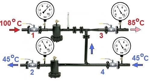
Check the working pressure in a high-rise building using tubular deformation pressure gauges. If, when designing the system, the designers laid down automatic pressure control and its control, then sensors of various types are additionally installed. In accordance with the requirements prescribed in the regulatory documents, control is carried out in the most critical areas:
- at the coolant supply from the source and at the outlet;
- before the pump, filters, pressure regulators, mud collectors and after these elements;
- at the outlet of the pipeline from the boiler room or CHP, as well as at its entry into the house.
Please note: 10% difference between standard working pressure on the 1st and 9th floor is normal
General information
For high-quality provision of all consumers with the required amount of heat in district heating, it is necessary to provide a given hydraulic regime. If the specified hydraulic regime in the heating network is not fulfilled, then high-quality heat supply to individual consumers is not ensured even with an excess of thermal power.
A stable hydraulic regime in heating networks is ensured by supplying individual buildings with a given amount of coolant circulating in the branches. To fulfill this condition, a hydraulic calculation of the heat supply system is made and the diameters of the pipelines, the pressure drop (pressure) in all sections of the heat network are determined, the available pressure in the network is provided in accordance with that required by the subscribers and the equipment necessary for transporting the coolant is selected.
Bernoulli equation for a steady flow of an incompressible fluid
where I is the total hydrodynamic head, m. st;
Z is the geometric height of the pipeline axis, m;
O - fluid velocity, m/s;
B\_2 - loss of pressure; m of water. Art.;
Z+ p/pg - hydrostatic head (R = Rat + RAND — absolute pressure);
png - piezometric head corresponding to gauge pressure (RAND— overpressure), m of water. Art.
In the hydraulic calculation of heat networks, the velocity head o212g is not taken into account, since it is a small fraction of the total head H and varies slightly along the length of the network. Then we have
i.e., they consider that the total head in any section of the pipeline is equal to the hydrostatic head Z + p/pg.
Pressure loss Ar, Pa (pressure D/g, m water column) is equal to
Here D/?dl - pressure loss along the length (calculated using the Darcy-Weisbach formula); Arm — pressure loss in local resistances (calculated using the Weisbach formula).
where x, ?, are the coefficients of hydraulic friction and local resistance.
Hydraulic friction coefficient X depends on the mode of fluid movement and the roughness of the inner surface of the pipe, the coefficient of local resistance ?, depends on the type of local resistance and on the mode of fluid movement.
Length loss. Coefficient of hydraulic friction X. Distinguish: absolute roughness To, the equivalent (equigranular) roughness Touh, the numerical values of which are given in reference books, and the relative roughness kid (kjd is the equivalent relative roughness). Values of the coefficient of hydraulic friction X calculated according to the following formulas.
Laminar fluid flow (Re X is calculated using the Poiseuille formula
Transition region 2300 Re 4, Blasius formula
turbulent movement {Re > IT O4), formula A.D. Altshulya
At Touh = 0, the Altshul formula takes the form of the Blasius formula. At Re —? oo Altshul's formula takes the form of Professor Shifrinson's formula
When calculating heat networks, formulas (4.5) and (4.6) are used. In this case, first determine
If Re ip, then X is determined by formula (4.5) if Re>Renr, then X calculated according to (4.6). At Re>Renp a quadratic (self-similar) resistance zone is observed when X is a function of only the relative roughness and does not depend on Re.
For hydraulic calculations of steel pipelines of heating networks, the following values of equivalent roughness are taken Touh, m: steam pipelines - 0.2-10″3; condensate pipelines and DHW networks - 1-10’3; water heating networks (normal operation) - 0.5-10″3.
In thermal networks, usually Re > Renp.
In practice, it is convenient to use the specific pressure drop
or
where /?l — specific pressure drop, Pa/m;
/ - pipeline length, m.
For the quadratic resistance region, the Darcy-Weisbach formula for the transport of water (p = const) is represented as
where L \u003d 0.0894?uh°'25/rv = 16.3-10-6 at ^ = 0.001 m, pv = 975.
(L = 13.62 106 at Touh = 0.0005 m).
Using the flow equation G= r • o • S, determine the diameter of the pipeline
Then
, 0,0475 0,5
Here A" = 0.63L; A* = 3,35 -2—; for 75 °С; Rv = 975; = 0,001;
R
A* = 12110″3; D? = 246. (When to, = 0.0005 m A% = 117-10’3, D? = 269).
Losses in local resistances are calculated using the concept of "equivalent length" 1E local resistance. Taking
we get
Substituting value X= OD 1 (Touh / d)0.25 in (4 L 0), we get
where A1 = 9.1/^3'25. For p = 975 kg/m3, Touh = 0.001 m A, = 51,1.
Ratio ARm to ART represents the proportion of local pressure losses
From the joint solution of equations (4.6), (4.10) and (4.11) we obtain
where
For water
where Apv — available pressure drop, Pa.
total pressure drop
Then
Coefficient values A and Av presented in .
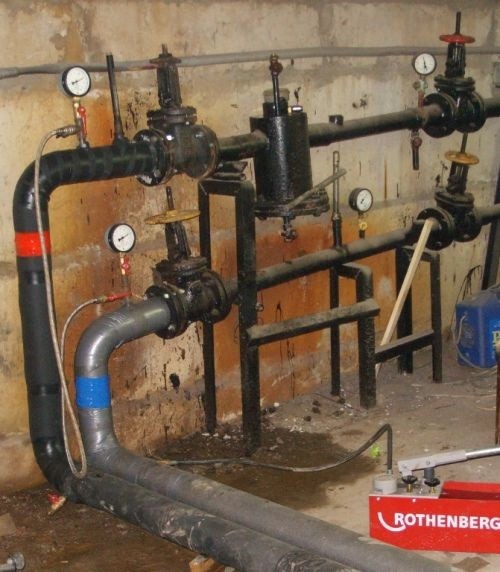
Checking the tightness of the heating system
The tightness test is carried out in two stages:
- cold water test. Pipelines and batteries in a multi-storey building are filled with coolant without heating it, and pressure indicators are measured. At the same time, its value during the first 30 minutes cannot be less than the standard 0.06 MPa. After 2 hours, the loss cannot be more than 0.02 MPa. In the absence of gusts, the heating system of the high-rise building will continue to function without problems;
- test using a hot coolant. The heating system is tested before the start of the heating season. Water is supplied under a certain pressure, its value should be the highest for the equipment.

But residents of multi-storey buildings, if desired, can install such measuring instruments as pressure gauges in the basement and, in case of the slightest deviations in pressure from the norm, report this to the relevant utilities. If, after all the actions taken, consumers are still unhappy with the temperature in the apartment, they may need to consider organizing alternative heating.
The pressure that should be in the heating system of an apartment building is regulated by SNiPs and established standards
When calculating, they take into account the diameter of the pipes, the types of pipelines and heaters, the distance to the boiler room, the number of storeys
Verification calculation
After all the diameters of the pipes in the system are determined, they proceed to the verification calculation, the purpose of which is to finally verify the correctness of the network, check the compliance of the available pressure at the source and ensure the specified pressure at the most remote consumer. At the verification calculation stage, the entire network as a whole is linked. The network configuration is determined (radial, ring). If necessary, according to the map of the area, the lengths / individual sections are adjusted, the diameters of the pipelines are again determined. The results of the calculation give grounds for the choice of pumping equipment used in the heating system.
The calculation ends with a summary table and drawing up a piezometric graph, on which all pressure losses in the heating network of the area are applied. The calculation sequence is shown below.
- 1. Pre-calculated diameter d The /-th section of the network is rounded up to the nearest diameter according to the standard (upwards) according to the range of pipes produced. The most widely used standards are: Dy = 50, 100, 150, 200, 250, 400, 500, 800, 1000 and 1200 mm. Larger pipes Dy = 1400 and ?>at= 1800 mm are rarely used in networks. Within the boundaries of Moscow, the most common backbone networks with a conditional diameter Dy = 500 mm. According to the tables, the steel grade and the assortment of pipes manufactured at the factory are determined, for example: d= 259 mm, Steel 20; d= 500 mm Steel 15 GS or others.
- 2. Find the number Re and compare it with the limit Renp, determined by the formula
If Re > Renp, then the pipeline operates in the region of a developed turbulent regime (quadratic region). Otherwise, it is necessary to use the calculated relations for the transient or laminar regime.
As a rule, backbone networks operate in a quadratic domain. The situation when a transient or laminar regime occurs in a pipe is possible only in local networks, in subscriber branches with a low load. The velocity v in such pipelines can decrease to the values v
- 3. Substitute the actual (standard) value of the pipeline diameter in formulas (5.32) and (5.25) and repeat the calculation again. In this case, the actual pressure drop Ar should be lower than expected.
- 4. The actual lengths of the sections and the diameters of the pipelines are applied to the single-line diagram (Fig. 5.10).
The main branches, accidents and sectional valves, thermal chambers, compensators on the heating main are also applied to the scheme. The scheme is performed on a scale of 1:25,000 or 1:10,000. For example, for a CHPP with an electric power of 500 MW and a thermal power of 2000 MJ / s (1700 Gcal / h), the network range is about 15 km. The diameter of the lines at the outlet from the CHP collector is 1200 mm. As water is distributed to associated branches, the diameter of the main pipelines decreases.
Actual values /, and dt each section and the number of thermal chambers, marks from the surface of the earth are entered in the final table. 5.3. The level of the CHPP site is taken as the zero mark of 0.00 m.
In 1999, a special program "Hydra”, written in the Fortran-IV algorithmic language and open to the public on the Internet. The program allows you to interactively make a hydraulic calculation and get a summary table of results. In addition to the table, re-
Rice. 5.10. One-line heating network diagram and piezometric graph
Table 5.3
The results of the hydraulic calculation of the main network of the district No. 17
|
Number cameras |
IT |
TO, |
TO2 |
To, |
Remote subscriber |
||
|
D |
— |
||||||
|
Section length, m |
h |
/z |
h |
L |
L+ |
||
|
Elevation of the ground surface, m |
0,0 |
||||||
|
Pipeline diameter |
d |
d2 |
d3 |
di |
dn |
da |
|
|
Head loss in the area |
TO |
h2 |
*3 |
L/ |
TO |
||
|
Piezometric head in the area |
"R |
H |
n2 |
Hi |
nP |
HL |
The result of the calculation is a piezometric graph corresponding to the heating network scheme of the same name.
If the pressure drops
In this case, it is advisable to immediately check how the static pressure behaves (stop the pump) - if there is no drop, then the circulation pumps are faulty, which do not create water pressure. If it also decreases, then most likely there is a leak somewhere in the pipelines of the house, the heating main or the boiler house itself.
The easiest way to localize this place is by turning off various sections, monitoring the pressure in the system. If the situation returns to normal at the next cutoff, then there is a water leak on this section of the network. At the same time, take into account that even a small leak through a flange connection can significantly reduce the pressure of the coolant.
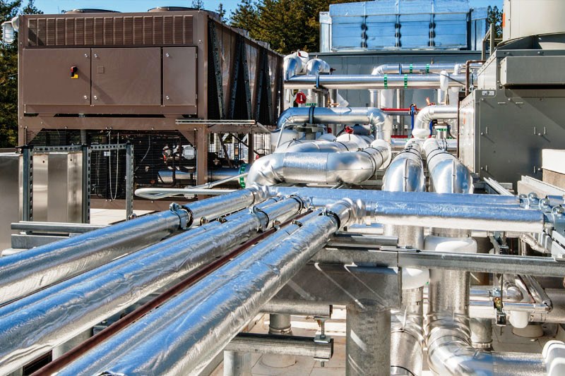
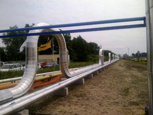
Calculation of heat networks
Water heating networks will be made two-pipe (with direct and return pipelines) and closed - without parsing part of the network water from the return pipeline to hot water supply.
Rice. 2.6 - Heating networks
Table 2.5
|
No. heat network account |
Network section length |
Heat load on site |
|
0-1 |
8 |
622,8 |
|
1-2 |
86,5 |
359,3 |
|
2-3 |
7 |
313,3 |
|
2-4 |
7 |
46 |
|
1-5 |
118 |
263,5 |
|
5-6 |
30 |
17,04 |
|
5-7 |
44 |
246,46 |
|
7-8 |
7 |
83,8 |
|
7-9 |
58 |
162,6 |
|
9-10 |
39 |
155,2 |
|
9-11 |
21 |
7,4 |
Hydraulic calculation of heat networks
a) Section 0-1
Coolant consumption:
, where:
Q0-1 is the estimated consumption of heat transmitted through this section, kW;
tp and to are the temperature of the heat carrier in the forward and return pipelines, °С
We accept the specific pressure loss in the main pipeline h = 70 Pa / m, and according to Appendix 2 we find the average density of the coolant c = 970 kg / m3, then the calculated diameter of the pipes:
We accept the standard diameter d=108 mm.
Friction coefficient:
From Appendix 4 we take the coefficients of local resistances:
- gate valve, o=0.4
- a tee for a branch, o=1.5, then the sum of the coefficients of local resistance ?o=0.4+1.5=1.9 - for one pipe of the heating network.
Equivalent length of local resistances:
Total pressure loss in the supply and return pipelines.
, where:
l is the length of the pipeline section, m, then
Hc \u003d 2 (8 + 7.89) 70 \u003d 2224.9 Pa \u003d 2.2 kPa.
b) Section 1-2 Coolant consumption:
We accept the specific pressure loss in the main pipeline h=70 Pa/m.
Estimated pipe diameter:
We accept the standard diameter d=89 mm.
Friction coefficient:
From app 4
- a tee for a branch, o=1.5, then ?o=1.5 - for one pipe of the heating network.
Total pressure loss in the supply and return pipelines:
\u003d 2 (86.5 + 5.34) 70 \u003d 12.86 kPa
Equivalent length of local resistances:
c) Section 2-4 Coolant consumption:
We accept the specific pressure loss in the branch h=250 Pa/m. Estimated pipe diameter:
We accept the standard diameter d=32 mm.
Friction coefficient:
From app 4
- valve at the entrance to the building, o=0.5, ?o=0.5 for one pipe of the heating network.
Equivalent length of local resistances:
Total pressure loss in the supply and return pipelines:
=2 (7+0.6) 250=3.8 kPa
The remaining sections of the heating network are calculated similarly to the previous ones, the calculation data are summarized in Table 2.6.
Table 2.6
|
Network Account No. |
Heat consumption, kg/s |
Calculation, dia, mm |
?O |
le, mm |
standard, diameter, mm |
Ns, kPa |
|
|
0-1 |
5,9 |
102 |
1,9 |
7,89 |
108 |
0,026 |
2,2 |
|
1-2 |
3,4 |
82 |
1,5 |
5,34 |
89 |
0,025 |
5,34 |
|
2-3 |
2,9 |
60 |
0,5 |
1,25 |
70 |
0,028 |
4,1 |
|
2-4 |
0,4 |
28 |
0,5 |
0,6 |
32 |
0,033 |
3,8 |
|
1-5 |
2,5 |
73 |
1,5 |
4,2 |
76 |
0,027 |
17 |
|
5-6 |
0,16 |
20 |
2 |
1,1 |
20 |
0,036 |
15,5 |
|
5-7 |
2,3 |
72 |
1,5 |
4,3 |
76 |
0,026 |
6,7 |
|
7-8 |
0,8 |
37 |
0,5 |
0,65 |
40 |
0,031 |
3,8 |
|
7-9 |
1,5 |
60 |
1,5 |
3,75 |
70 |
0,028 |
8,6 |
|
9-10 |
1,4 |
47 |
2 |
3,4 |
50 |
0,029 |
21,2 |
|
9-11 |
0,07 |
15 |
0,5 |
0,18 |
15 |
0,04 |
10,5 |
?Hc=98.66 kPa
Selection of network pumps.
For forced circulation of water in heating networks in the boiler room, we install network pumps with an electric drive.
Supply of the network pump (m3 / h), equal to the hourly consumption of network water in the supply line:
,
where: Fr.v. \u003d Fr - Fs.n. is the calculated heat load covered by the coolant - water, W;
Fen. - thermal power consumed by the boiler house for own needs, W
Fs.n \u003d (0.03 ... 0.1) (? Ph.t. +? Fv +? Fg.v.);
tp and to - calculated temperatures of direct and return water, °С
со is the density of return water (Appendix 2; at to=70°C со =977.8 kg/m3)
Fs.n=0.05 747.2=37.36 kW
Fr.v \u003d 747.2-37.36 \u003d 709.84 kW, then
The pressure developed by the network pump depends on the total resistance of the heating network. If the coolant is obtained in hot water boilers, then the pressure losses in them are also taken into account:
Нн=Нс+Нк,
where Hk - pressure losses in boilers, kPa
Hc=2 50=100kPa (p. ),
then: Нн=98.66+100=198.66 kPa.
From Appendix 15, we select two centrifugal pumps 2KM-6 with an electric drive (one of them is a reserve one), the electric motor power is 4.5 kW.
Heat carrier for condensate network
The calculation for such a heat network differs significantly from the previous ones, since the condensate is simultaneously in two states - in steam and in water. This ratio changes as it moves towards the consumer, i.e. the steam becomes more and more humid and eventually completely turns into a liquid. Therefore, the calculations for the pipes of each of these media have differences and are already taken into account by other standards, in particular SNiP 2.04.02-84.
Procedure for calculating condensate pipelines:
- According to the tables, the internal equivalent roughness of the pipes is established.
- Indicators of pressure loss in pipes in the network section, from the outlet of the coolant from the heat supply pumps to the consumer, are accepted according to SNiP 2.04.02-84.
- The calculation of these networks does not take into account the heat consumption Q, but only the steam consumption.
The design features of this type of network significantly affect the quality of measurements, since pipelines for this type of coolant are made of black steel, sections of the network after network pumps due to air leaks quickly corrode from excess oxygen, after which low-quality condensate with iron oxides is formed, which causes metal corrosion.Therefore, it is recommended to install stainless steel pipelines in this section. Although the final choice will be made after the completion of the feasibility study of the heating network.
How to raise the pressure
Pressure checks in the heating lines of multi-storey buildings are a must. They allow you to analyze the functionality of the system. A drop in pressure level, even by a small amount, can cause serious failures.
In the presence of centralized heating, the system is most often tested with cold water. The pressure drop for 0.5 hours by more than 0.06 MPa indicates the presence of a gust. If this is not observed, then the system is ready for operation.
Immediately before the start of the heating season, a test is performed with hot water supplied under maximum pressure.
Changes occurring in the heating system of a multi-storey building, most often do not depend on the owner of the apartment. Trying to influence the pressure is a pointless undertaking. The only thing that can be done is to eliminate air pockets that have appeared due to loose connections or improper adjustment of the air release valve.
A characteristic noise in the system indicates the presence of a problem. For heating appliances and pipes, this phenomenon is very dangerous:
- Loosening of threads and destruction of welded joints during vibration of the pipeline.
- Termination of the supply of coolant to individual risers or batteries due to difficulties in de-airing the system, the inability to adjust, which can lead to its defrosting.
- A decrease in the efficiency of the system if the coolant does not stop moving completely.
To prevent air from entering the system, it is necessary to inspect all connections and taps for water leakage before testing it in preparation for the heating season. If you hear a characteristic hiss during a test run of the system, immediately look for a leak and fix it.
You can apply a soapy solution to the joints and bubbles will appear where the tightness is broken.
Sometimes the pressure drops even after replacing old batteries with new aluminum ones. A thin film appears on the surface of this metal from contact with water. Hydrogen is a by-product of the reaction, and by compressing it, the pressure is reduced.
Interfering with the operation of the system in this case is not worth it.
The problem is temporary and goes away on its own over time. This happens only in the first time after the installation of radiators.
You can increase the pressure on the upper floors of a high-rise building by installing a circulation pump.
Steam heating networks
This heating network is intended for a heat supply system using a heat carrier in the form of steam.
The differences between this scheme and the previous one are caused by temperature indicators and pressure of the medium. Structurally, these networks are shorter in length; in large cities, they usually include only the main ones, that is, from the source to the central heating point. They are not used as intra-district and intra-house networks, except at small industrial sites.
The circuit diagram is carried out in the same order as with the water coolant. On the sections, all network parameters for each branch are indicated, the data is taken from the summary table of marginal hourly heat consumption, with a step-by-step summation of consumption indicators from the end consumer to the source.
The geometric dimensions of pipelines are established based on the results of a hydraulic calculation, which is carried out in accordance with state norms and rules, and in particular SNiP. The determining value is the pressure loss of the gas condensate medium from the source of heat supply to the consumer.With a greater pressure loss and a smaller distance between them, the speed of movement will be large, and the diameter of the steam pipeline will need to be smaller. The choice of diameter is carried out according to special tables, based on the parameters of the coolant. The data is then entered into pivot tables.
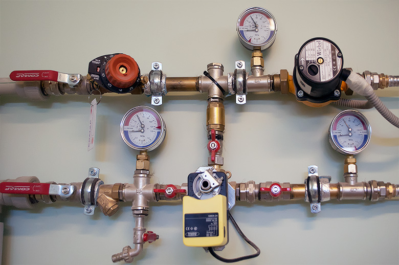
How to control system pressure
To control at various points in the heating system, pressure gauges are inserted, and (as mentioned above) they record excess pressure. As a rule, these are deformation devices with a Bredan tube. In the event that it is necessary to take into account that the pressure gauge must work not only for visual control, but also in the automation system, electrocontact or other types of sensors are used.
The tie-in points are defined by regulatory documents, but even if you have installed a small boiler for heating a private house that is not controlled by GosTekhnadzor, it is still advisable to use these rules, since they highlight the most important heating system points for pressure control.
The control points are:
- Before and after the heating boiler;
- Before and after the circulation pumps;
- Output of heat networks from a heat generating plant (boiler house);
- Entering heating into the building;
- If a heating regulator is used, then the pressure gauges cut in before and after it;
- In the presence of mud collectors or filters, it is advisable to insert pressure gauges before and after them. Thus, it is easy to control their clogging, taking into account the fact that a serviceable element almost does not create a drop.
A symptom of a malfunction or malfunction of the heating system is pressure surges. What do they stand for?