5 General data on working drawings
5.1 General data on working drawings (GOST 21.101) of heating, ventilation and air conditioning systems include:
a) a list of working drawings of the main set;
b) a list of reference and attached documents;
c) a list of the main sets of working drawings;
d) symbols;
e) general instructions;
e) layout plan for the placement of system installations;
g) characteristics of systems;
i) the main indicators according to the working drawings of the OB grade.
5.2 List of working drawings of the main set (clause , listing a) are in form 1 GOST 21.101.
5.3 List of reference and attached documents (clause , listing b) are in form 2 GOST 21.101.
5.4 List of main sets of working drawings (clause , listing v) are compiled in the form 2 of GOST 21.101 in the presence of several main sets of working drawings of the OB grade and are given on the sheet of general data for each of these sets.
5.5 On the sheet of general data on the working drawings, symbols are given (clause , listing G), not established by state standards, the values \u200b\u200bof which are not indicated on other sheets of the main set of working drawings of the OV grade.
5.6 In general instructions (, listing d) lead:
— the basis for the development of working drawings of the OV grade (design assignment, approved feasibility study (project) for construction, approved (approved) justifications for investments in construction for technically simple objects);
– a record of the results of the check for patentability and patent purity of processes, equipment, devices, structures, materials and products for the first time used or developed in the project, as well as the numbers of copyright certificates and applications for which decisions were made to issue copyright certificates for inventions used in the working documentation ;
- a record that the working drawings are developed in accordance with applicable norms, rules and standards;
— information about who owns this intellectual property (if necessary);
— design parameters of outdoor and indoor air;
- data on the heat carrier, coolant (name, flow rate, parameters);
- references to the Construction Norms and Rules (SNiP) and other regulatory documents, according to which the calculation of heating, ventilation and air conditioning systems was made;
- requirements for the manufacture, installation, testing, anti-corrosion protection, thermal and fire insulation, fire-retardant coating of air ducts and pipelines, as well as the composition of insulating structures;
— special requirements for installations (explosion safety, acid resistance, etc.);
- a list of types of work for which it is necessary to draw up certificates of examination of hidden works.
In general instructions, one should not repeat the technical requirements placed on other sheets of the main set of working drawings of the OV grade, and describe the technical solutions adopted in the working drawings.
5.7 On the layout of system installations (p. , listing e) are applied:
- contour of the building (structure);
- the coordination axes of the building (structure) and the overall dimensions between the extreme coordination axes;
— system installations;
— coolant input;
- heating point.
The installations of the systems on the plan diagram are depicted by dots with a diameter of 1–2 mm indicating the designation of the installation on the shelf of the leader line and under the shelf - the number of the sheet on which the drawing of the installation is shown.
The name of the plan-scheme for placing installations of systems is indicated in abbreviated form - "Plan-scheme".
An example of the implementation of the layout plan for the placement of system installations is given in the appendix.
5.8 Characteristics of systems (clause , enumeration well) is performed in the form of a table in the form of . In the absence of certain types of equipment in the systems, the corresponding columns are excluded from the table.
If the table is divided into parts, then at the beginning of each subsequent part, the column "System designation" is placed.
In standard projects, the characteristics of air heaters and, if necessary, other equipment are indicated for the calculated outside air temperatures adopted by the project.
5.9 The main indicators according to the working drawings of the OB grade (p., listing and) is performed in the form of a table in the form of . If necessary, additional columns are included in the table (for example, specific heat consumption).
2 Normative references
Present
the standard uses references to
the following standards:
GOST
2.316-68
ESKD. Drawing rules
inscriptions, technical requirements and
tables
GOST
2.782-96
ESKD. Conditional graphic designations.
Hydraulic and pneumatic machines
GOST
2.785-70
ESKD. Conditional graphic designations.
Pipe fittings
GOST
21.101-97
SPDS. Basic requirements for the design
and working documentation
GOST
21.110-95
SPDS. Specification execution rules
equipment, products and materials
GOST
21.112-87
SPDS. Handling equipment.
Conditional images
GOST
21.114-95
SPDS. Rules for sketching
drawings of general views of non-standard products
GOST
21.205-93
SPDS. Symbols for elements
sanitary systems
GOST
21.206-93
SPDS. Symbols of pipelines
GOST
21.404-85
SPDS. Automation of technological
processes. Symbols for conventional devices
and automation tools in diagrams
GOST
21.501-93
SPDS. Execution rules
architectural and construction workers
drawings
GOST
3262-75
Pipes steel water and gas.
Specifications
3 Definitions
Present
The standard uses the following definitions:
3.1 system:
Complex
functionally related.
equipment, installations (blocks),
devices, products, pipelines and
(or) air ducts (for example, a system
supply P1, exhaust system V1, system
heating 1, heating system
installations P1 - P3).
3.2 drawing
systems: Drawing,
relative location
functionally related.
equipment, installations (blocks),
pipelines and (or) air ducts and
other parts of the designed systems.
3.3 installation:
Conditional
name of the complex of interconnected
equipment and (or) devices, and when
the need for pipelines (air ducts),
attached to the installation equipment
systems (for example, installation of a supply
systems P1, installation of an exhaust system
IN 1).
3.4 drawing
settings: Drawing,
containing a simplified image
installations that determine their design,
dimensions, relative position and
designation of installation elements and
other necessary data.
3.5 Applied in
this standard terms according to GOST
21.110 and
GOST
21.114
are given in Appendix A.
EEE
7 Entrance to the tunnel, combined with forced ventilation
|
. 4 |
mm |
|
|
l I I |
||
|
>rk |
i - |
8 Tunnel entrance combined with exhaust ventilation
——N-
9 Hatch on the tunnel
3 minutes
Note - Symbols on network plans are depicted on a scale in accordance with Table 2, but not less than the dimensions indicated in the "Designation" column.
12
GOST 21.705-2016
Annex B
(reference)
An example of the implementation of a heat network plan

13
GOST 21.705-2016
Annex B
(reference)
An example of a heat network scheme

14
Annex D
(reference)
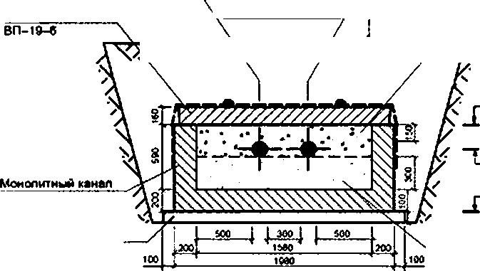
GOST 21.705-2016
Examples of cross-sections of heating networks
1-1
Т4 ТЗ Т2 Т1 Тb Т5

Figure D.1 - Cross section for underground laying
3*3
T2 T1 Tb T5
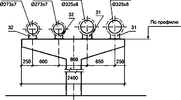
Figure D.2 - Cross section for above-ground laying
1S
GOST 21.705-2016
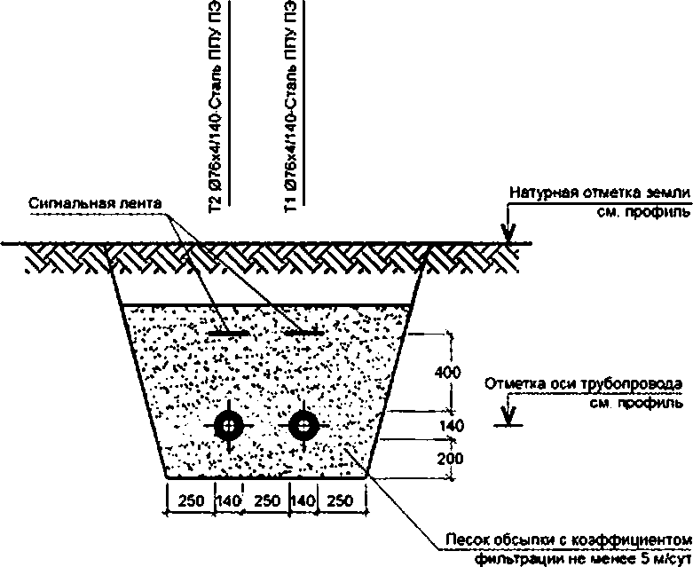
Figure G.3 - Cross-section with no-cap laying in a trench
overlap ptta
1*2 076x4L4O-Stap PLU-LE
J1 076×4/140-PPU-PE steel natural ground mark
see profile
7V7J meadow L&G y.\ry-i
NNV; NN^NN^NN^ANCn V.VVTx filtration not less than 5 s/yut
Channel ceiling elevation
see profile
Elevation of the axis of the pipeline, see profile Elevation of the bottom of the channel
no pass concrete preparation
see profile
Base sand with a filtration coefficient of at least 5 m/day
Figure D.4 - Cross section when laying networks in the filling channel
16
GOST 21.705-2016
Т2 07bх4L4О-Stap PPU-LE

Figure D.5 - Cross section. Channelless laying and a trench for concrete preparation
17
5400
GOST 21.705-2016
Annex E
(reference)
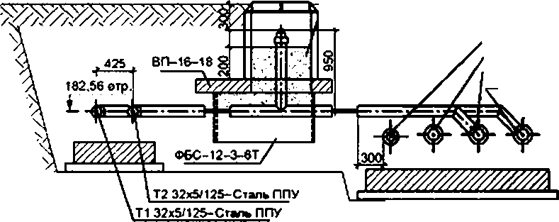
Examples of executing a piping node plan
UTZ

Figure E.1 - Captivity of the pipeline node with underground channel laying
1v
GOST 21.705-2016
ТЗ 133х5/225-PPU steel T2 133×5/225-PPU steel

Figure E.2 - Plan of the pipeline assembly for channelless laying
Mixed sap with a filtration coefficient of at least S s / day
$183.61
T4Yu8k&«180-StapPPU TZ 133k5^225-PPU steel T2 133x5/225-PPU steel T1 133x5/225-PPU steel
r 182.28 1r. /
L 502 L S25 I 525 ]
Figure E.3 - Cross-section of a piping assembly for a trenchless laying
19
GOST 21.705-2016
UDC 697.34.002.5:002:006.354 MKS 01.100.30 Zh01
Key words: heat network, pipelines, pipeline elements, pipeline fittings, U-shaped compensators, network diagrams, elements of heat networks, channelless laying, non-linear channels, angles of rotation
Editor L.S. Bogachsnkova Tezhiesky editor 8.N. Prusakova Proofreader O-v. Lazareva Computer layout A.N. Zolotareva
Handed over to the set 21.122016. Signed and stamped 20.02.2017. Format 60»64^£ Headset Arial. Uel. oven l. 2.79 * acl 0.93. Uch.-iad. item 2.S2 * incl. 0.83. Circulation 48 zke. Per". 374. Based on the electronic version provided by the developer of the standard
Published and printed by FSUE kSTANDARTINFORM. 123885 Moscow. Garnet lane.. 4.
GOST 21.705-2016
Annex D
(reference)
Examples of execution of heat network profiles

Figure E.1 - An example of the design of a longitudinal profile for underground channel laying
Figure E.2 - An example of the shape of the longitudinal profile of the wireless gasket
GOST 21.705-2016