Introduction
The UPS of the specified model in the event of a power outage, by virtue of its circuit implementation, is only able to de-energize the load, it itself remains on. This article describes how to fix this deficiency.
The unit described here can be used with any model of Back-UPS, in which case the communication port information given here may not be correct.
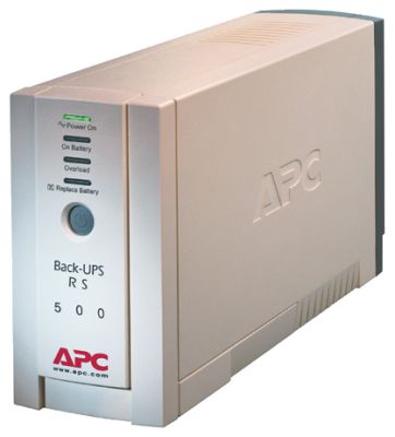
Overview of UPS, communication port and interface cable 940-0020B
The APC Back UPS 600I uninterruptible power supply has a StandBy (Off-Line) topology - fig. one.
Rice. 1. Standby topology
A UPS built according to this scheme is often called the term "Off-Line UPS". At any particular moment of time, it can be in one of 2 modes of operation - Stand-by or On-line. In the case when the voltage in the network is within the acceptable limits (Standby mode), the transfer switch is switched to the flow of the load current through the “Surge suppressor - Filter” circuit. In this mode, UPS is no different from an ordinary network filter. No voltage stabilization occurs. During operation in this mode, the UPS batteries are also being charged.
In the event that the mains voltage goes beyond the allowable limits, the transfer switch switches to powering the load via the “Battery – DC / AC inverter” circuit (On-line mode), i.e. from the energy of the storage battery, converted by the inverter into AC 220V. Since the switching of the contacts and the start of the inverter cannot be instantaneous, the power supply to the load will be interrupted for some time (Transfer Time). Most Standby UPSs provide Transfer Time on the order of 4-8 ms. The peculiarity of this system is that switching to On-Line when the mains voltage goes beyond the permissible limits occurs immediately, and returning to Standby mode - with a mandatory delay of several seconds. Otherwise, with multiple power surges in the network, there would be a continuous switching of Standby / On-Line and vice versa, which would lead to significant distortion of the load current and its possible failure or failure in its operation.
It should be taken into account that this circuit usually does not have the ability to stabilize the voltage when working in Standby mode and, therefore, goes into On-Line with every deviation in the mains voltage. The discharge of the battery is much faster than the reverse charge. The power of the battery charger for this scheme is usually chosen relatively small, and does not compensate for the energy consumption from the batteries during brownouts. Therefore, this UPS topology is unsuitable for use in case of poor quality of the supply network for two reasons:
-
a) With frequent transitions to On-Line, the battery is quickly discharged, not having time to restore the charge during the Standby mode, as a result of which the UPS loses the ability to provide emergency power to the load during the required time;
-
b) Frequent repetition of discharge/charge cycles will shorten the life of the batteries.
The description of the topology is taken from (see the list of sources used at the end of the article).
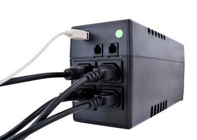
Communication port
The UPS has a communication port (Fig. 2) for communication with the computer's COM port.
Rice. 2. APC Back UPS communication port
Purpose of the port legs:
- 1. Shutdown UPS. Under battery power, a high RS-232 voltage causes the inverter to shut down and power off the load. The UPS responds to this signal only when the load is powered by battery. The APC website states that the signal must be valid for 1 second, however, experimental testing has shown that the UPS responds to the signal immediately.
- 2. Line fail. In RS-232 levels. A high level means switching to battery power.
- 3. Line fail. open collector. Normally open.
- 4.GND
- 5.Battery low. open collector. Normally open.
- 6. Line fail. open collector. normally closed.
- 7. Not used.
- 8. Not used
- 9.GND
The RS-232 high level is about +12V relative to port ground, the low level is about -12V.
Note: when developing any intermediate circuits, TTL levels can also be used. UPS and COM-port react to them normally.
Information about the port layout and the purpose of its contacts is official, taken from (see the list of sources used at the end of the article).
Step-by-step algorithm of actions
The algorithm of actions for self-manufacturing a power supply from an old UPS will be as follows:
- the transformer is disconnected from the UPS, the future case of the device is being prepared;
- using an ohmmeter, the winding with the highest resistance value is determined: black and white wires, which in the future will serve as an input to the device (if the old case from the UPS is used for manufacturing, then the input will be the corresponding socket located at the end of the uninterruptible power supply and serving for connection of the device and socket);
- from the wires located on one side of the location of the core, an "input" is formed, from the wires located on the opposite side, the "output" of the device is equipped;
- the transformer is supplied with alternating current with a voltage of 220 volts;
- voltage is removed from unused contacts;
- a pair is determined that has a potential difference of 15 volts (white and yellow wires - “output”);
- a diode bridge is installed on the "output";
- consumers are connected to its contacts.
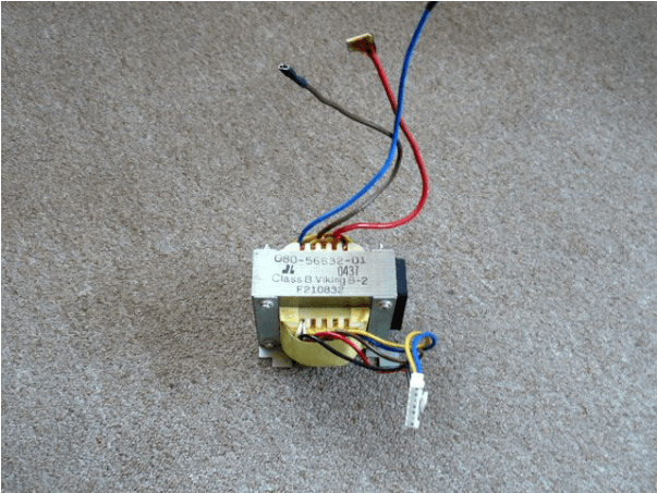
Schemes and explanations
Figure 1 shows a standard transformer from a UPS with typical wire colors referenced in the DIY power supply instructions.
How to make a laboratory power supply
Making a laboratory power supply from an old uninterruptible power supply is a more difficult task. The laboratory power supply is often used by radio amateurs. In addition to the transformer from the old UPS, you will also need:
- powerful transistor;
- diodes for voltage rectification;
- microcircuit (from OU);
- relay;
- a set of LEDs;
- varistor;
- connectors;
- oxide capacitors;
- ceramic capacitors.
The explication of the power supply is shown in Figure 2.
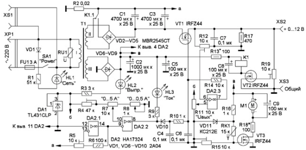
The primary winding of the transformer receives voltage from the network through the inserted element FU1 and the power supply switch SA1. Connected in parallel RU1 (varistor) serves as protection against power surges.
With the help of R1 (current limiting resistor) and VD1 (diode), the HL1 LED is powered, which acts as an indicator of the presence of mains voltage.
To winding || a voltage rectifier is connected, located on VD2-VD5 (diode fees). The position of the relay contacts K 1.1 determines the operation of the transformer as a full-wave transformer with a voltage of around 10 V or as a bridge with a voltage of approximately 20 V. From the rectifier, the voltage is supplied to the field-effect transistor.
With the help of capacitors C1 and C3, ripples are smoothed out. With the help of resistor R17, the minimum load of the voltage stabilizer is ensured.
From the rectifier assembled on VD6-VD9 (diodes), with the participation of C2 and C5 (capacitors), the parallel stabilizer is powered by:
- microcircuits (DA1, op-amp DA2);
- relay K1;
- fan M1.
HL2 (LED) gives a signal when there is voltage in this rectifier.
The current limit threshold is set by resistors:
- R7;
- R8.
The relay (K1) is controlled by a resistor (VT2). The output voltage is set by R19 (trimming resistor). When it is exceeded, the relay switches the output voltage. When the maximum temperature set by R15 (resistor) is exceeded, VT3 (transistor) and RK1 (thermistor) start M1 (fan). The excessive relay and fan voltages are distributed to R13 and R18 (resistors) respectively.
When the threshold value of the load current is exceeded, the output voltage of the op-amp decreases. VD 10 (diode) opens, reducing the voltage at VT1 (transistor gate) to normal values that ensure the flow of current. The current limit is set by R8 and R7 (resistors) in the ranges of 0-0.5 A and 0-5 A, respectively. With the help of capacitors, the stable operation of the current limiter is ensured.
With an increase in their capacity, the value of stability also increases, but the value of the speed of the current limiter decreases.
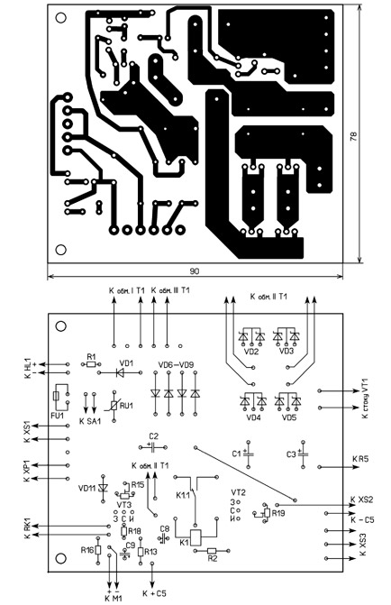
Figure 3 shows assembled rectifiers, transistors in mounting with interconnected elements.The transformer outputs are equipped with sockets, if necessary, they are used for the installation of the corresponding plugs, soldered from the board from the old UPS.
The adjustment should begin by determining the maximum output voltage using R12 (resistor) with the slider located at the top in the circuit. Using the selection of R13 (resistor) on K1 (relay), the nominal voltage value is set. On the fan, the voltage is set by R18 (resistor).
The output current limiter is adjusted by connecting a series-connected ammeter and a variable resistor with a resistance of 15 ohms and a power of 50 watts.
Resistors R1, R7 are set to the position in the circuit on the left, and R8 is on the right, with its help the output current is adjusted.
The current limit mode will allow you to charge the batteries by setting the end voltage and current. Further refinement is carried out by installing equipment:
- voltmeter;
- ammeter;
- complex measuring device.
Switching power supplies how they work overview of circuits
The block diagram of a switching power supply is illustrated by mnemonic symbols of the voltage form above each of its constituent blocks, and the interaction links are indicated by arrows.
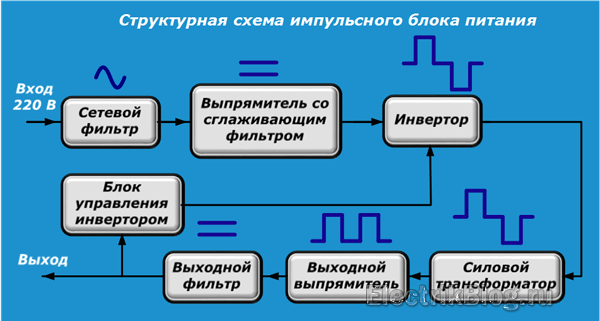
It is convenient to represent the circuit diagram in this form.
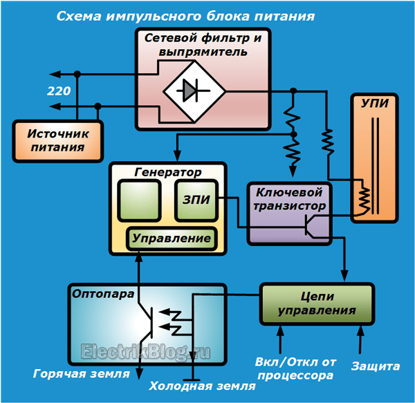
The circuit board of one of the devices with the location of the parts is shown in the photo below with my comments.
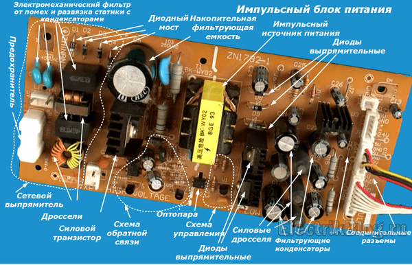
Naturally, this is only a special case, which most likely will not match your UPS. Here I pursue a simple goal - to recall the principles of interaction of the component parts of the block.
If you need to learn more about these issues, then read a specially written article.
2 Options in use
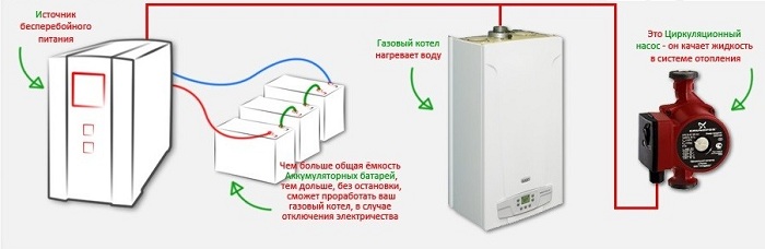
Most heating systems run on natural gas. In order for all equipment to work efficiently and without failure, a stable power supply must be integrated into such systems.
In the event of an unexpected power outage, the system without such equipment will turn off and begin to cool down, which may lead to its failure.
UPS for redundant gas boiler pumps
With constantly occurring power surges (a fairly common occurrence in all power networks), a stable output voltage can also be obtained using a UPS. In this case, such a device will simultaneously be both a stabilizer and a battery.
To create a backup power source for the pump and automation of the heating system, you will need a battery, an inverter and a charger.
When choosing any uninterruptible power supply, you should pay attention to the parameters of the output voltage. In the instructions attached to the device, it should be clearly indicated - pure sine
Quasi-sine, approximated sine, quasi-sinusoidal shape - are not suitable, because when they are used, the automatic control of the system quite often fails, which leads to overheating and breakdown of both the pump and automatic heating burners.
2.1 Expert advice
When buying and installing, pay attention to the following points:
- the device must be reliable, of high quality and economical in terms of energy consumption, since in emergency situations it will have to work for several hours;
- the price of equipment should not affect the choice, because its operation will last for many years;
- additional (spare) batteries will be required to increase the battery life);
- if the UPS is included in the heating system, then it is not allowed to connect other devices to it, such as a refrigerator, a deep pump or similar devices or devices;
- location (mounting) can be floor and wall. With large dimensions of the device and high power, it is better to install it on the floor;
- The installation room can be a basement or semi-basement, in which a hermetically sealed cabinet is pre-installed, which provides waterproofing (absence of moisture) on the batteries and the device itself.
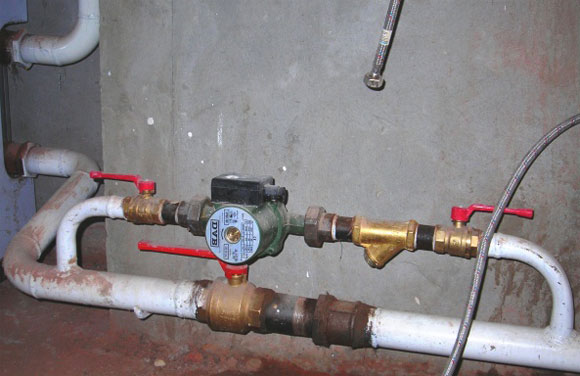
Example of a mounted bypass with a pump in a heating system
2.2 Homemade uninterruptible power supply
Making such a necessary device for specialists with their own hands is not an insoluble task.
As a basis, it is necessary to use an inverter, which is equipped with a meander at the output. To obtain a pure sine wave, a special filter must be added. One way to convert a square wave to a pure sine wave is to turn on a pulse converter.
Naturally, the exact parameters of do-it-yourself equipment can only be obtained by a person who knows the principles of electrical engineering well.
When solving the problem - how to make an uninterruptible power supply with your own hands correctly, you should immediately take into account that car batteries are not recommended for use for this purpose. In addition, the minimum capacity of charged batteries must be at least 100 Ah.
When operating the heating system in places where a long power outage is possible, you should acquire an autonomous power plant or generator. This will allow you to enter two modes of operation - night and day. At night, the system is powered only by the UPS, and during the day it is powered by a generator that simultaneously charges the batteries.
Homemade uninterruptible device
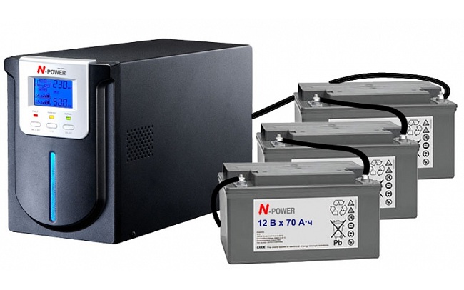
In order to increase the duration of the uninterruptible power supply, you should connect several batteries of the same charge level and the same capacity. The connection can be series, to increase the voltage without changing the capacitance, or parallel, which will increase the capacitance without changing the voltage.
Batteries should not be placed close to each other and when placed, they are best placed indoors at room temperature. The presence of a nearby heat source, as well as the influence of cold, adversely affects the performance of batteries, significantly reducing their performance.
The use of an uninterruptible power supply in the heating system is optional. But despite the additional costs, it allows you to be sure that you won’t have to spend money on repairing equipment that has failed due to a power outage.
1 Why you need a UPS
Stationary power transmission systems from the producer to the consumer quite often present surprises in the form of a power outage. This happens for a variety of reasons that are not so important, except for the very fact that there is no light.
When this happens, heating systems, including electric pumps, stop the circulation of the coolant, its individual elements overheat and fail.
There are three ways out of this situation:
- Calculate and build a heating system in which there is no electric pump. Circulation in this case should occur due to the influence of gravitational forces and the difference in the density of the heated and cold liquids in the pipes during supply and return. For the efficient operation of such a heating system, pipes of large diameter must be used (which is not very convenient) and at the same time, no adjustments are foreseen during operation.
- In the form of an alternative generation of electricity - install a generator (diesel or gasoline). But it will require a separate room, since during operation such devices produce a lot of noise and emit exhaust gases that must be removed. In addition, the cost of fuel significantly increases the cost of providing residential premises with heat.
- Install an uninterruptible heating pump to ensure a constant circulation process that runs on battery power.When the centralized power supply is turned off, the UPS will automatically replace it, which will convert the direct current from the batteries to alternating current using an inverter. Such additional equipment does not take up much space and can be located in any convenient place. The UPS also does not require special maintenance, the main thing is to ensure that the batteries are always charged.
The simplest scheme of the UPS
The UPS is used not only in gas, but also in solid fuel boilers, which significantly increases the reliability of their uninterrupted operation when the power is turned off.
1.1 Types of UPS
An uninterruptible switch for a heating pump can have several versions:
- a linear UPS is the simplest model that does not have a voltage regulator. When the stationary power supply is interrupted, such a device independently switches to battery power;
- line-interactive UPS - equipped with the simplest voltage stabilizer and when running on battery power, it outputs the required 220V and 50Hz;
- double conversion UPS. In addition to the voltage stabilization system, it has the ability to connect to a generator.
Line-interactive devices have low internal voltage, which allows them to operate from 1 to 4 batteries.
In this case, an independent control of the amount of charge occurs and when the residual capacity of the battery is below 20%, it is turned off. Switching to standalone mode in case of a power outage and vice versa occurs automatically.
UPS selection and capacity determination
The choice of IPD should be approached very seriously. All characteristics of the power supply must match the requirements of the equipment. In the event of an error, there is a high probability that the electrical devices of the heating circuit may simply burn out or, at best, not work properly.
Uninterruptibles for a heating circulation pump and a boiler come in two classes, which differ only in the presence of a voltage stabilizer:
- linear (on-line);
- linear-interactive (off-line).
Linear uninterruptible power supplies are not equipped with a voltage stabilizer and transmit it in transit from the network, generator or batteries. Line-interactive uninterruptible power supplies are also called double conversion UPS. This option is better, because the voltage is converted to the correct sinusoid, which cannot be said about linear units. Voltage stability without drops is very important for heating system equipment. Off-line uninterruptibles are more expensive.
Both types of UPS are always connected to the network and are activated automatically when there is a power outage. In addition to the functions already described by them, they also charge the batteries connected to them, some models control the level of battery discharge
In addition to the fact that the characteristics of the UPS must match the requirements of the equipment, it is also important to determine the capacity of the uninterruptible power supply.
The use of more powerful units is allowed, but why overpay for an unnecessary resource?
To calculate the power of the UPS, you need to sum up all the consumed and peak power of the devices in the circuit. The documentation for the boiler and pump has their power consumption.
The power consumption of the pump does not reflect the real power demand of this circuit element, since its starting power is higher than the consumed power. That is, the backup power for the heating pump must be calculated with a good margin. After summing up, you will get a value to which you need to add another twenty percent so that the UPS does not work at its limit.
What can be done
From the old uninterruptible power supply, you can get a lot of devices in haste. Among other things, among them it should be especially noted useful in everyday life:
- Charger;
- simple inverter;
- UPS for gas boiler;
- 12 volt source (for radio and other purposes).
Charger
To make a charger out of an old uninterruptible power supply, you need to proceed as follows:
- firstly, the primary and secondary circuits of the transformer are determined;
- 220 V is supplied to the primary by inserting into the voltage regulator circuit (a rheostat for a light bulb is suitable);
- a bridge of about 40-50 amperes is connected to the secondary transformer winding;
- connect the terminals and the corresponding poles of the battery.
Voltage calibration will be carried out by an impromptu regulator within 0-15 volts.
You will have to control the charge level according to the indicator or using a voltmeter.
Simple inverter
A transformer without a battery will make a working inverter for a car. The assembly process will proceed as follows:
- disassembly of the uninterruptible power supply: removal of the battery, bite off the terminals, stripping the ends;
- search for a connector for connecting to the network (if there is a connector, it should be removed, if not, the wires are bitten off the board, the ends are stripped);
- the wires from the battery with a soldering iron must be connected to the wires from the connector located on the rear panel, the soldering points are not isolated;
- the cigarette lighter socket is soldered to the device, observing the polarity and insulating the soldering points;
- the internal speaker of the device is excluded (it is torn off with pliers or the board is removed);
- assembling the case by adding standard sockets (for some UPSs, they are already included in the original design).
UPS for gas boiler
A computer UPS is also suitable for a gas boiler. The conversion process should be done as follows:
- removal of a faulty power supply;
- creation of terminal clamps, taking into account the observance of polarity (it is better to make clamps of different colors to indicate plus and minus) by making 2 holes, fixing the terminal clamps and soldering to them the wires previously suitable for the internal power supply from the computer;
- to prevent premature failure of the device due to overheating, it will be necessary to install fans with or without a housing connected in series (to start them, it is recommended to use an LED by soldering its leads to the winding of a small relay, and you will need to solder a wire from the incoming “+” battery to one of the relay contacts battery, and to the second - a free red wire from the fan, another free black wire is soldered to the minus of the battery).
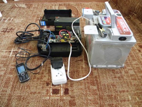
12 volt source
A failed uninterruptible power supply can also be adapted to a 12 volt source. This is done very simply. First, you will need to connect an outlet to the uninterruptible power cord. To do this, one end is initially cut off from it. After completing this procedure, using an uninterruptible power supply, you can already charge the phone. By further simple transformations described above, you can increase the power of a home-made device (see the part about the inverter).
Thus, an old uninterruptible power supply from a computer is suitable for various purposes. The described devices are only an incomplete list of what can be done with elementary knowledge in physics.
Therefore, we recommend that you do not rush to throw out the old computer - there can be a lot of interesting things inside!
We also draw special attention of all our readers to the need for strict observance of safety precautions and precautions.
Power selection
 Before buying, you should make some calculations. For the coordinated operation of the entire system, it is necessary to correctly select a power unit that matches the parameters of your devices. The general principle of calculation is that the total power of all computer devices should not exceed the power of the UPS. The capabilities of a power supply depend on its output power, which is measured in Volt-Amps and is calculated by multiplying the voltage by the current.
When self-calculating the required power, do not forget that.the power of the computer and connected devices is indicated in Watts, and the power of the unit in VA. Adjust as needed, taking into account that 1 watt equals approximately 1.45 Volt-Amps.
In the final selection, it's a good idea to add a 10-20% standby UPS capacity to ensure your equipment is protected. The safety of using an ordinary home computer with a 17-inch monitor will be able to provide a unit with a power of 400 VA or more.
What are
 All produced blocks can be conditionally divided into three types:
- Reserve. USP low power. The main function is switching to battery power during battles in the network and vice versa when the voltage normalizes;
- Interactive. They are most often used for home and office computers. The device has a stabilizer, which gives a sinusoidal voltage at the output;
- Online power supplies. In the course of their work, a double voltage conversion occurs. The input AC current is converted to DC, and the inverter converts it back to AC. It is used when large DNS servers and stations are running.
In medium and high power units, there is a special device for connecting the input and output directly, without using a backup power, called a bypass. In case of overloads, the power from the inverter is sent to the bypass, which saves current consumption.
The correct selection of the block includes selection by power, type and purpose of use.