Boiler gas valve principle of operation and setting
The gas valve is required to supply gas to the burner device of the unit. By adjusting the gas valve, you can adjust the amount of fuel supplied. This makes it possible to make the unit more economical or increase the power of the device. Thus, the user, depending on the situation, has the opportunity to adjust the performance of his unit.
…
How does a gas valve work?
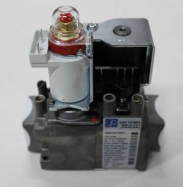
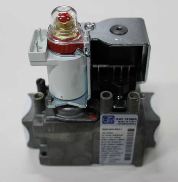
Most gas appliances have a SIT valve. It includes the following elements:
- measuring fitting of gas pressure at the outlet of the valve;
- adjusting screw for minimum and adjusting nut for maximum fuel consumption;
- lid;
- inlet pressure gauge.
The gas boiler valve consists of a locking and modulating coil. When voltage of 220 V is applied to the shut-off valve, the minimum volume of gas is supplied to the burner in accordance with the factory settings. The voltage is then transferred to the modulation coil. The processor, depending on the operating mode (power), supplies voltage with a different modulation frequency, adjusting the amount of gas passing per unit of time.
To set the boiler gas valve to minimum power, you will need a differential pressure gauge, a wrench and a screwdriver. The setup process includes the following steps:
- Remove the protective cap covering the valve differential screws.
- Open the fitting to measure the pressure of the gas supplied to the burner - turn the locking screw counterclockwise by 1.5-2 turns.
- Connect the manometer hose to the inlet fitting.
- They turn on the heating mode and turn off one wire of the modulating coil - this is necessary so that the valve supplies gas to the burner to a minimum, which will correspond to the minimum power of the unit.
- According to the pressure gauge, set the minimum gas pressure on the burner. To do this, rotate the internal screw located under the protective cap. At the same time, the outer nut is fixed.
The dynamic fuel pressure at the inlet of the gas valve is in the range from 1.4 to 2.4 kPa. If the measurements show that the pressure is outside the specified limits, it is necessary to call gas specialists.
…
It is not necessary to reset the gas valve manually in the factory power range. This is required in order to transfer the unit to a power lower or higher than the indicators stated in the instructions. Often, valve adjustment is needed if the performance of the device does not correspond to the heated area of \u200b\u200bthe house or apartment.
Setting the gas valve when the boiler is "clocked"
Such a problem as the “clocking” of a gas boiler can be solved by adjusting the gas valve. Usually it occurs if the power of the unit significantly exceeds that required for a given area.
…
To exclude "clocking" of the device in heating mode, it is necessary to reduce the outlet pressure. This is done by turning the adjusting screw counterclockwise.
To stop "clocking" in the DHW mode, reduce the maximum pressure. This is solved by turning the adjusting nut counterclockwise.
However, in more modern models, “clocking” is eliminated by automation. For example, setting the gas valve of the Buderus boiler is done by blocking cycles:
- hold the button with a wrench for 5 seconds;
- select the duration of the intervals from 0 to 15 minutes using the arrow buttons.
It is recommended that settings of this kind be carried out only by service center specialists, especially if the boiler is under warranty. Otherwise, if you damage the valve, the company will void the warranty and you will have to buy a new part.
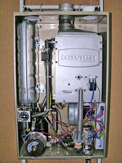
Warm home Setting the gas pressure of Navien boilers
Setting the gas pressure of Navien boilers
To adjust the gas pressure of Navien boilers (Ace, Deluxe, Prime, Atmo), you will need a differential digital pressure gauge with a scale of mm h3O
A table with gas pressure values \u200b\u200bfor various models of Navien boilers is given at the end
1. With the boiler turned off, connect a manometer to the gas pressure control port on the burner
2. Turn on the boiler
3. Set DIP switch 3 on the control board to the "ON" position, which will correspond to the minimum load.
4. Set the minimum gas pressure according to the table with the screw for setting the minimum pressure (Increase - counterclockwise, decrease - clockwise)
5. Set DIP switch 3 on the control board to "OFF" (Basic state)
6. Set DIP switch 2 on the control board to the "ON" position, which corresponds to the maximum load
7. Set the maximum gas pressure in accordance with the table with the adjusting screw (Increase - counterclockwise, decrease - clockwise)
8. Turn off the boiler
9. Disconnect the differential pressure gauge hose from the gas valve fitting
10. Set the DIP switch to the "OFF" position (Basic state)
11. Turn on the boiler
12. Check the tightness of the gas valve (fitting). If abnormal noises appear, it is required to check the boiler for gas leakage.
The material was prepared by an employee of heating-mtsensk.rf - Warm House.
Gas type
Pressure in mm h30
Nozzle diameter (mm)
Maximum
Minimum
Prime-13k
Natural gas
32
14
1,75
Liquefied gas
55
25
1,2
Prime-16k
Natural gas
46
14
1,75
Liquefied gas
82
25
1,2
Prime-20k
Natural gas
68
14
1,75
Liquefied gas
124
25
1,2
Prime-24k
Natural gas
98
14
1,75
Liquefied gas
160
25
1,2
Prime-30k
Natural gas
113
18
1,75
Liquefied gas
164
31
1,2
Prime-35k
Natural gas
107
18
1,75
Liquefied gas
165
28
1,2
Gas type
Pressure in mm h30
Nozzle diameter (mm)
Maximum
Minimum
Ace-10k
Natural gas
20
11
1,75
Liquefied gas
33
17
1,2
Ace-13k
Natural gas
33
11
1,75
Liquefied gas
55
17
1,2
Ace-16k
Natural gas
43
16
1,75
Liquefied gas
76
25
1,2
Ace-20k
Natural gas
61
16
1,75
Liquefied gas
13
25
1,2
Ace-24k
Natural gas
83
16
1,75
Liquefied gas
164
25
1,2
Ace-30k
Natural gas
91
20
1,75
Liquefied gas
170
33
1,2
Ace-35k
Natural gas
82
22
1,75
Liquefied gas
140
33
1,2
Ace-40k
Natural gas
90
15
2
Liquefied gas
115
17
1.45
Gas type
Pressure in mm h30
Nozzle diameter (mm)
Maximum
Minimum
Ace Coaxial-10k
Natural gas
19
11
1,75
Liquefied gas
33
17
1,2
Ace Coaxial -13k
Natural gas
31
11
1,75
Liquefied gas
55
17
1,2
Ace Coaxial -16k
Natural gas
45
16
1,75
Liquefied gas
82
27
1,2
Ace Coaxial-20k
Natural gas
70
16
1,75
Liquefied gas
119
27
1,2
Ace Coaxial -24k
Natural gas
94
16
1,75
Liquefied gas
152
27
1,2
Ace Coaxial -30k
Natural gas
93
21
1,75
Liquefied gas
171
33
1,2
Gas type
Pressure in mm h30
Nozzle diameter (mm)
Maximum
Minimum
Atmo-13
Natural gas
75
40
1,3
Liquefied gas
127
71
0,92
Atmo-16
Natural gas
110
40
1,3
Liquefied gas
184
71
0,92
Atmo-20
Natural gas
76
18
1,3
Liquefied gas
127
32
0,92
Atmo-24
Natural gas
108
18
1,3
Liquefied gas
185
32
0,92
Gas type
Pressure in mm h30
Nozzle diameter (mm)
Maximum
Minimum
Deluxe-13k
Natural gas
30
11
1.75
Deluxe-16k
Natural gas
43
16
1.75
Deluxe-20k
Natural gas
65
16
1.75
deluxe-24k
Natural gas
89
16
1.75
Deluxe-30k
Natural gas
95
19
1.75
Deluxe-35k
Natural gas
97
18
1.75
Deluxe-40k
Natural gas
90
13
2
Gas type
Pressure in mm h30
Nozzle diameter (mm)
Maximum
Minimum
Deluxe-13k
Natural gas
28
11
1.75
Deluxe-16k
Natural gas
41
16
1.75
Deluxe-20k
Natural gas
63
16
1.75
deluxe-24k
Natural gas
85
16
1.75
Deluxe-30k
Natural gas
92
19
1.75
selection of a device for measuring gas pressure and adjusting a heating device
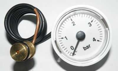
The manometer exists to measure the pressure in the system. It connects with an emergency safety valve and an air vent, thus guaranteeing safety.
If the pressure readings are out of range, the system is not working properly. Excessive pressure can lead to rupture of the pipeline and even to the explosion of the equipment.
Vkontakte
Odnoklassniki
Classification of pressure gauges for setting up gas boilers
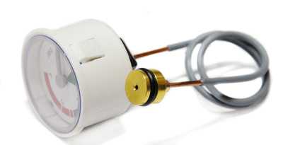
The principle of operation of all pressure gauges is based on the fact that the measured pressure is balanced by the force of a tubular spring or a double-lamellar membrane.
At one end it is soldered to the holder, and at the other end it is connected to the arrow through a special mechanism. This mechanism converts the linear movement of the sensing element into the movement of the arrow on the dial.
exemplary
Exemplary are measuring instruments that are used to calibrate others. This type of device is used to test equipment and accurately measure liquid and gas pressure, they have a higher accuracy class - 0.015-0.6 units.The increased measurement accuracy of these devices is due to the design features: the gear body in the transmission mechanism is made very accurately.
Electrocontact
These devices monitor the limit pressure and notify the system when it is reached. Typically, this type of measuring equipment is used for gas, steam, calm liquids that are not prone to crystallization. Devices can control external electrical circuits when critical pressure is reached using a contact group or an optical pair.
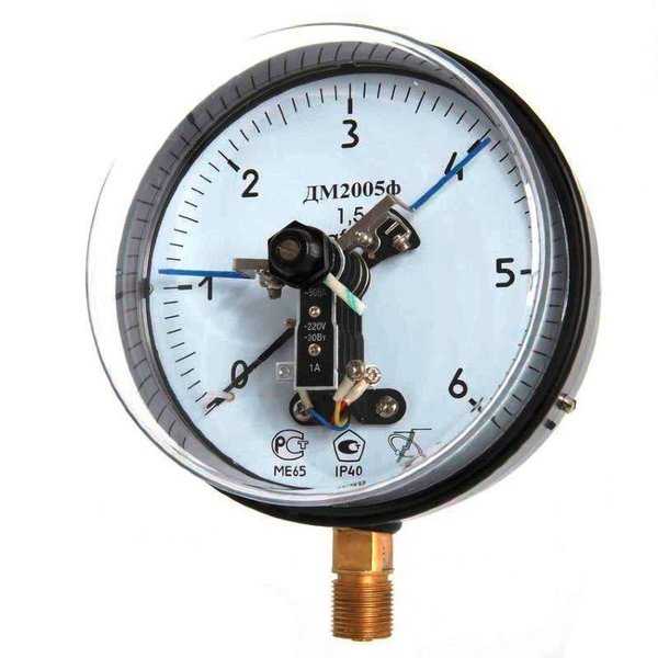
Photo 1. Electrocontact pressure gauge for a heating gas boiler. The device has a dial with divisions.
Measuring devices for setting heating systems
Due to rising energy prices, the correct setting of the operation of heating equipment is becoming an important component for optimizing utility costs. Testo's portable flue gas analyzers help you complete any task of setting up, commissioning and servicing heating equipment.
Professional gas analysis with testo 330-1 LL
h4>
The testo 330-1 LL gas analyzer with extended sensor life is a reliable tool for diagnosing faults in heating equipment and for monitoring emissions of harmful substances into the atmosphere or for the daily work of heating specialists. It is able to fulfill the highest requirements placed on a gas analyzer: the highest sensor accuracy and sensor lifetime.
Professional gas analysis with testo 330-2 LL
h4>
In addition to all the advantages of the Testo 330-1 LL gas analyzer, you can use the testo 330-2 gas analyzer at higher CO concentrations in flue gases. This is achieved by the built-in function of automatic dilution of the flue gas sample by a factor of 5. Additional convenience is achieved by using the zeroing function of the pressure/draft sensor with the probe remaining in the chimney.
High performance gas analysis with testo 320
h4>
Gas analyzer Testo 320 is a multifunctional flue gas analyzer for heating specialists. The intuitive menu structure and ease of use of the testo 320 gas analyzer, combined with the high-resolution color display, allow you to carry out all the necessary measurements during installation, commissioning, service and maintenance of heating boilers and burners.
Base level gas analysis testo 310
h4>
The testo 310 gas analyzer combines ease of use with high measurement accuracy and is ideally suited for all basic measurements on gas boilers and burners. A long battery life guarantees the possibility of long-term use of the device, including for a series of flue gas concentration measurements
Particulate number analyzer Testo 308
h4>
The Testo 308 soot analyzer helps you measure your soot. The built-in pump and the automatic display of the measured value on the backlit display provide information on the soot content in the chimney using a modern measurement method. This measurement method is comparable to traditional methods for measuring soot using a hand pump.
Easy data management with easyHeat software
h4>
With the dedicated Testo software you can easily transfer the data from your gas analyzer to a PC for further processing. A wide range of functions, such as customer and metering data management, allows you to optimize the work of planning service activities at your customers' sites.