2. Starting the boiler plant
3.2.1. Before firing up the boiler, it is necessary to carry out
pre-start check of the closing of the shut-off devices on the fuel oil pipelines before
burners and ignition devices in accordance with the operational
instruction.
3.2.2. Before starting the boiler after a downtime of
more than 3 days, serviceability and readiness for switching on must be checked
draft mechanisms of the boiler, its auxiliary equipment, means
measurement and remote control of fittings and mechanisms, automatic regulators,
as well as checking the operability of protections, locks, means
operational communications and checking the operation of the slam-shut. When idle for less than 3 days
equipment, mechanisms, protection devices, interlocks, means
measurements on which repairs were made. Identified faults before launch
boiler must be eliminated.
3.2.3. Before starting the boiler,
ensure the pressure of oil and steam, air and thrust in accordance with the requirements
operating instructions.
Fuel oil temperature before mechanical and steam-mechanical
nozzles must correspond to its viscosity no more than 2.5 ° VU, and before
steam and rotary nozzles - no more than 6 °VU.
3.2.4. Just before ignition
burners must be ventilated for at least 10 minutes
gas ducts (including recirculation) with open gas-air dampers
path and air flow not less than 25% of the nominal. Conditions to ensure
the required air flow rate for ventilation must be specified in the local
instructions. At the same time, the "warm box" must be ventilated.
3.2.5. Ventilation of pressurized boilers, as well as
hot water boilers in the absence of smoke exhausters should be carried out by blast
fans and smoke exhausters for gas recirculation.
3.2.6. Kindling of boilers with balanced draft must be carried out
when the smoke exhausters and blowers are on, and the kindling of boilers operating
under supercharging - when the blower fans are on.
3.2.7. The kindling of the boiler on sulphurous fuel oil must be carried out
with a pre-heated air preheating system
air heater.
3.2.8. According to the terms of explosion safety, kindling the boiler on
oil can start with the ignition of any burner or group of burners and
be carried out in the sequence indicated in the instruction manual
boiler plant.
3.2.9. In case of extinction or non-ignition during ignition, any
from the burners, the supply of fuel oil to it must be immediately stopped, turned off
ignition device. The kindling of the boiler can continue with the ignition of subsequent
burners if at least one burner remains in operation. If not at work
there is not a single burner left, then you should be guided by the indication of p. Re-ignition of a disabled
burner must be carried out after the causes of its extinction have been eliminated or
non-ignition.
3.2.10. Ignition of burners during kindling
the boiler must be fired with an ignition device; shutdown
the ignition device should be carried out after stabilization of the combustion of the torch
burners.
(New edition. Rev. No. 2)
3.2.11. In the event of a flare break in
the furnace, the fuel supply to the boiler must be immediately stopped and the
igniters. Only after ventilation of the furnace and gas ducts has been carried out for 10
mines and eliminate the causes of the extinguishing of the firebox, you can start kindling.
Advantages of oil boilers
- There are quite obvious advantages of liquid fuel boilers used in industries related to fuels and lubricants. For private houses, the advantages of boilers of this type may raise questions:
- Boilers for liquid fuel have a high efficiency from 86 to 98%.This is a good indicator, and it is very close to the indicators of gas boilers;
- The undoubted plus of diesel boilers, unlike gas boilers, does not require permits (approvals) for the installation of the boiler. Although you still have to equip the furnace room;
- Diesel boilers are produced in the most autonomous configurations. Boiler automation and automatic fuel supply minimize the presence of a person for maintenance;
- Another plus is the ability to quickly and easily change the boiler burner and switch to working with natural gas;
- Although there are no omnivorous boilers, diesel boilers can run on alternative types of liquid fuels, as indicated in the boiler documentation;
- Boilers for liquid fuel can be entered into any heating system and can work with any coolant (water and antifreeze).
Oil farm
The oil farm consists of an open oil storage and a control room. The oil warehouse usually has ground metal tanks installed on foundations made of separate reinforced concrete racks. The open storage of oil is fenced off from the rest of the territory by an earthen rampart 1.2 m high with continuous sodding. To drain surface water and drain oil in the event of an accident of tanks, the surface of the warehouse has a slope towards sewer wells, from which it is planned to release water or oil outside the TPP site. The oil facilities must have four tanks of turbine oil and four tanks of insulating oil. The capacity of each tank is not less than the capacity of a railway tank car - 70 m 3, in addition, the permissible minimum capacity depends on the capacity of the oil system of the turbine unit and transformer. For emergency draining of turbine oil at the power plant, a special tank is provided.
Rice. 9.6. Scheme of a vortex furnace with intersecting jets: 1 - cold radiation surface; 2 - the surface of the furnace, covered with refractory
coating; 3 - fuel supply
Receiving and draining device
The railway unloading rack for receiving railway tanks with fuel oil is constructed in the form of two longitudinal walls, between which a drain tray is arranged. The walls are made of concrete blocks. Depending on the height of the trestle wall and the carrying capacity of the tanks, reinforced concrete belts are made along the bottom and top of the walls.
When supplying fuel oil in tanks with a carrying capacity of 50-60 tons, a flyover with a drain tray can be made of a lightweight design without a reinforced concrete bottom. A more advanced overpass with a drain tray made of reinforced concrete I-beams 5.6 m long and weighing 12.5 tons each, which are the walls of the overpass, has also been developed (Fig. 5.16). The lower tees of the walls are connected by loop joints, which are monolithic and form the bottom. The walls along the top in the longitudinal direction are connected by loop joints. In order to avoid freezing of the base, slag filling is performed under the bottom of the tray. The tray for the drain of fuel oil has a longitudinal slope of 0.01 to the center of the overpass, from where the fuel oil is drained into an intermediate tank. The outlet trays are made of structures similar to those of a railway overpass.
The receiving capacity of the main fuel oil facilities should be designed for at least 15% of the capacity of tanks installed for unloading. Typically, the receiving tank is two underground tanks with a capacity of 600-1000 m 3 . To service the tanks, a special overpass is constructed from prefabricated reinforced concrete elements.
3. Boiler plant
2.3.1. The design of the boiler furnace and the placement of burners in it
must ensure the possibility of conducting a sustainable combustion process and control
behind this process and eliminate the possibility of the formation of stagnant and poorly
ventilated areas.
2.3.2. The introduction of recirculating gases into the combustion chamber is not
should violate the stability of the combustion process.
2.3.3. For newly designed boiler plants
with a steam capacity of at least 60 t/h, equipped with explosive
safety valves, frames and metal structures of the furnace and gas ducts
must be designed for pressure inside the furnace and gas ducts exceeding
atmospheric at least 200 kgf/m2 (2000 Pa). Furnace frames and
gas ducts of newly designed boilers with a steam capacity of 60 t/h and above,
whose equipment with explosive safety valves is
optional, must be designed for an internal pressure greater than
atmospheric at least 300 kgf / m2 (3000 Pa), for installations,
operating under vacuum, and for internal pressure exceeding the maximum
working not less than 300 kgf/m2 (3000 Pa), for installations,
working under pressure.
2.3.4. Peepers must be installed in the boiler furnace,
providing the possibility of monitoring combustion and excluding the possibility
flame ejection. Doors of manholes, hatches and peepers in the furnace and gas ducts of the boiler
must be tight and have strong constipation, excluding their spontaneous
opening.
2.3.5. Gas ducts on the line for the removal of combustion products and
gas ducts for recirculation of combustion products into the boiler furnace should not have
unventilated areas where it could linger or accumulate
combustible gas.
2.3.6. Air path of the boiler from the air heater to
burners must be designed in such a way that it is possible to
full ventilation by blowing into the furnace.
2.3.7. On boilers, the volume where collectors and
boiler hangers (“warm box”) must be ventilated.
2.3.8. Platforms for maintenance of oil nozzles, as well as
above the exhaust openings of the explosive safety valves of the firebox and
gas ducts must be continuous.
2.3.9. In boiler plants with a steam capacity of less than
60 t/h, except for boilers made of membrane gas-tight panels and boilers
with one-way movement of gases, explosive safety valves
are established in cases provided for by the current "Rules for the design and
safe operation of steam and hot water boilers”.
At boiler plants with a steam capacity of 60 t/h and
above explosive safety valves in the firebox and throughout the air and
gas paths up to the chimney may not be installed, if this is not
provided by the boiler design.
Gas ducts from the boiler to the chimney must be designed for
operating pressure (vacuum).
2.3.10. Boilers must be equipped with cleaning equipment
convective heating surfaces and air heaters.
2.3.11. Boiler air heaters must be equipped
fire extinguishing means. As a primary fire extinguisher
water should be used. To extinguish a fire in the convective shaft of the boiler with
tubular air heater is allowed instead of water to use superheated
or dry saturated steam.
2.3.12. Pilot burners of operating boilers must be
equipped with safety devices. Other burners of operating boilers
must be equipped with ignition devices (IgD) or ignition protection devices (IgD).
All burners of newly commissioned boilers must be equipped with an RPD.
2.3.13. Each burner should be equipped with a peeper,
allowing to observe the torch of this burner and the state of the nozzle.
2.3.14. It should be possible to disable
supplying fuel to the burner manually from the service platform.
2.3.15. The fastening of the nozzle to the block must provide
tightness of the connection and quick removal and installation of the nozzle. Application
gaskets in the connection of the nozzle with the block is not recommended.
3. Normal operation of the boiler plant
3.3.1. During the operation of the boiler, it is necessary to monitor:
maintenance of the combustion regime in accordance with the regime map,
preventing the operation of the furnace with chemical incomplete combustion of fuel and removal from
sooty particle furnaces;
fuel oil pressure after the control valve, preventing
reducing it below the limit specified in the regime card;
fuel oil temperature in front of the nozzles, preventing its decrease
below the values determined in accordance with the instructions of paragraph ;
torch, especially when switching from one type of fuel to
another without allowing it to fade.
3.3.2. Cleaning the heating surfaces of the operating boiler must
carried out in accordance with the instructions for use.
3.3.3. Inspection of fuel oil pipelines of the boiler room should be carried out
regularly according to the approved schedule. Inspection times are set at
in accordance with the "Rules for the technical operation of power plants and
networks."
3.3.4. At least once per shift must be carried out
visual inspection of working nozzles, and if necessary, they should be replaced.
Oil nozzles before installation on the boiler must be
tested on a water bench to verify their performance and quality
spray.
At the power plant (boiler house) should be allocated
Responsible for the stand and checking oil nozzles on it.
3.3.5. It is forbidden during a bypass of a working boiler
open hatches, manholes on the boiler, except for short-term opening
inspection hatches and peepers, provided that they are located on the side of them.
dead end scheme
Applicable for
combustion of relatively low-viscosity
fuel oil when the boiler is running
at stable loads exceeding
medium (Fig. 9.3). Fuel for pumps 3
arrives
from the supply tank 5.
When installing
consumption tank in the boiler room, it should
be closed, with a volume of not more than 5 m3.
It is not allowed to install consumable
tanks above boilers and economizers.
The diagram must include
oil circulation from pressure
fuel oil pipeline of pumps to the consumable
containers.
During boiler operation
valves on oil pipelines downstream of burners
boilers are closed. When the boilers stop
these valves open and turn on
into operation the recirculation line for the consumable
capacity. Fuel oil in a storage tank,
comes from main tanks
oil storage facilities.
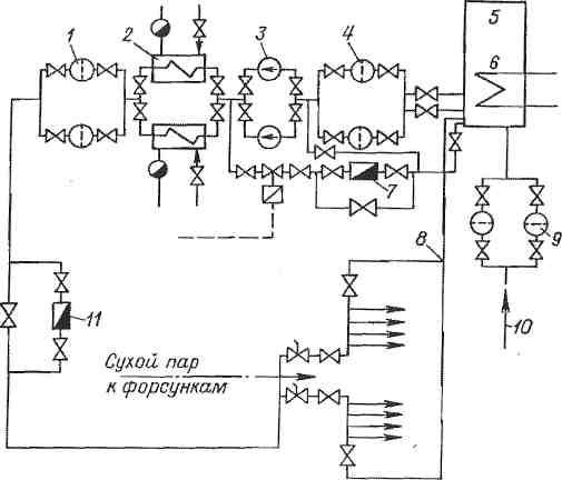
Rice. 9.3. dead end
liquid fuel supply scheme.
1 —
fine filter; 2
and
6 — heaters
car; 3 —
pump; 4 and
9 —
coarse filters; 5 - capacity
consumable; 7 and 11 - fuel oil meters; eight -
circulation section; 10
- feed
fuel from the main tank.
Fuel consumption
determined by fuel oil meter 11,
As
fuel oil meters can be used as
rotary counters, and
special constriction devices. Accounting
fuel consumption at a dead-end scheme
simpler than with circulation:
accounting is carried out for one fuel oil meter before
boilers.
Topic11. Oil burners
Oil nozzles (mechanical, with atomizing medium,
steam-mechanical combined, rotary): design, principle of operation,
scope, advantages and disadvantages. Air guide devices.
Oil nozzles.
The nozzle is one of three devices (along with
air guide and lance - loophole), forming a burner.
Thermal power plants are supplied with gas from gas distribution stations (GDS) through gas distribution points (GDP) (Fig. 5.1.) The latter, together with the gas pipeline system, constitute the gas facilities of TPPs. At gas-oil condensing power plants with a capacity of up to 1200 MW and gas-oil CHPPs with a steam flow rate of up to 4000 t/h, there can be one hydraulic fracturing, and at other power plants their number must be at least two. The productivity of hydraulic fracturing at power plants where gas fuel is the main one is calculated for the maximum gas consumption by all working boilers, and at power plants that burn gas seasonally, based on gas consumption for the summer regime, hydraulic fracturing is located in separate buildings or under sheds on the territory of the power plant.Gas is supplied to each hydraulic fracturing through one gas pipeline (without backup) from a gas distribution station located outside the territory. Gas pressure before hydraulic fracturing is 0.6–1.1 MPa, and after hydraulic fracturing, its required value is determined by pressure losses to the boiler furthest from hydraulic fracturing and the required gas pressure in front of the burners and is usually 0.13-0.2 MPa.
Rice. 5.1.
I—
gate valve, 2 - flow meter, 3 - filter, 4 - pressure regulator, 5 - safety valve, 6 - bypass line, 7 - gas flow regulator; 8 - impulse shut-off quick-acting valve, 9 - plug valve.
The hydraulic fracturing has working lines of the gas pipeline, low-flow lines switched on at low gas consumption, and a reserve line with manual valve control. On the working threads and threads of low flow, automatic pressure regulators and protective regulators are installed, operating on the principle of "after themselves". The safety regulators are set to a higher pressure than the working pressure and are fully open when operating in the calculated range.
Within the hydraulic fracturing and up to the boilers, the laying of gas pipelines is ground. The gas supply from each hydraulic fracturing station to the boiler room main line and from it to the boilers is not reserved and can be performed as a single-line one. The gas distribution manifold of the boilers is laid outside the boiler room building.
When filling with gas, gas pipelines must be purged with gas through the discharge candles until all air is displaced, and when released from gas, they must be purged with air until all gas is displaced. These requirements are due to the fact that at a volume concentration of natural gas in the air of 0.05-0.15 (5-15%), an explosive mixture is formed. Gas is released from waste candles to places from where it cannot enter buildings and where the possibility of its ignition is excluded from any fire source. Only steel fittings are installed on gas pipelines.
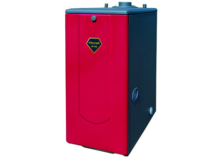
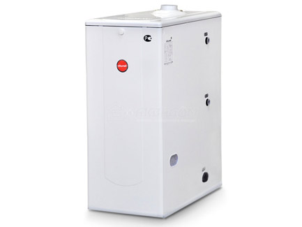
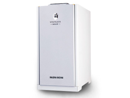
Oil boiler manufacturers

Power: 0 - 13 kW, heated area: up to 130.0 m 2, voltage: 220 V., combustion chamber: closed, number of circuits: double-circuit (heating and hot water), heat exchanger: separate (stainless steel / stainless steel) , dimensions (HxWxD): 754x320x520
Power: 0 - 16.8 kW, heated area: up to 130.0 m 2, voltage: 220 V., combustion chamber: closed, number of circuits: double-circuit (heating and hot water), heat exchanger: separate (stainless steel / stainless steel) , overall dimensions (HxWxD): 700x325x602
Power: 0 - 17 kW, heated area: up to 170.0 m 2, voltage: 220 V., combustion chamber: closed, number of circuits: double-circuit (heating and hot water), heat exchanger: separate (stainless steel / stainless steel) , dimensions (HxWxD): 754x320x520
Power: 0 - 21 kW, heated area: up to 210.0 m 2, voltage: 220 V., combustion chamber: closed, number of circuits: double-circuit (heating and hot water), heat exchanger: separate (stainless steel / stainless steel) , dimensions (HxWxD): 754x320x520
Power: 15 - 15 kW, heated area: up to 150.0 m 2, voltage: 220 V., combustion chamber: closed, number of circuits: double-circuit (heating and hot water), heat exchanger: separate (stainless steel / stainless steel) , dimensions (HxWxD): 930x365x650
Power: 13 - 13 kW, heated area: up to 130.0 m 2, voltage: 220 V., combustion chamber: closed, number of circuits: double-circuit (heating and hot water), heat exchanger: separate (stainless steel / stainless steel) , overall dimensions (HxWxD): 781x370x683
Power: 17 - 17 kW, heated area: up to 170.0 m 2, voltage: 220 V., combustion chamber: closed, number of circuits: double-circuit (heating and hot water), heat exchanger: separate (stainless steel / stainless steel) , overall dimensions (HxWxD): 781x370x683
Power: 0 - 19.8 kW, heated area: up to 190.0 m 2, voltage: 220 V., combustion chamber: closed, number of circuits: double-circuit (heating and hot water), heat exchanger: separate (stainless steel / stainless steel) , overall dimensions (HxWxD): 700x325x602
Power: 19.8 - 19.8 kW, heated area: up to 190.0 m 2, voltage: 220 V., combustion chamber: closed, number of circuits: double-circuit (heating and hot water), heat exchanger: separate (stainless steel / stainless steel) , overall dimensions (HxWxD): 920x360x640
Liquid fuel heating equipment is very popular in the domestic market, which is explained by its autonomous operation and modern automation.
The only drawback of these systems is the high cost of fuel and direct installation of equipment. Its installation will be fully justified in areas where there is no connection to the gas main. Sometimes, solid fuel equipment is a good alternative to liquid fuel boilers, but only if there is an energy source in the immediate vicinity.
Below we consider the design and principle of operation of a liquid fuel boiler, as well as its installation.
Types and modes of operation of burners for liquid fuels
Some manufacturers sell oil-fired boilers without burners. And that's why. The choice of burners for liquid fuels is quite large and there are many differences in types and modes of operation.
Burner types
The following types of burners are distinguished by fuel:
- Mono fuel burners. They work only on one type of liquid fuel, more often on diesel fuel. To switch to oils, you will have to change the burner nozzles.
- Bi fuel burners. They operate on several, often two, types of fuel. There are combinations, diesel-gas, diesel-firewood, diesel-wood-coal, etc.
Types of burners by operating mode
We also pay attention to this:
The burner is single stage. Pretty primitive, because of this, a reliable burner. Adjustment is made by simple inclusion/switching off of a torch. Differ in the maximum return of power and the maximum consumption of fuel.
The burner is multistage. Such a burner is configured to work according to complex algorithms for smooth on / off, through intermediate power values. Such burners are expensive, but they save diesel fuel perfectly. Typically, these burners are on powerful boilers from 40 kW.
Topic10. Preparation of liquid fuel for combustion.
Schematic diagram of the fuel oil economy of the boiler house. Fuel oil preparation
to combustion (heating temperature, use of additives).
Schematic diagram of the fuel oil economy of the boiler house.
When operating boiler plants, fuel oil
used as: the main and only type of fuel; reserve and
emergency fuel, when the main fuel is gas; starting fuel,
when the main one is solid fuel burned in pulverized form.
Delivery of fuel oil is usually carried out
rail transport in tanks. For installations located on a small
distance from oil refineries, fuel oil is supplied through pipelines.
Fuel oil management during the delivery of fuel oil
railway transport consists of the following structures and devices:
drain rack and intermediate tank; oil pump with pumps for
fuel oil pumping; fuel oil storage facilities with reinforced concrete or metal
reservoirs; fuel oil pipeline systems between fuel oil tanks, fuel oil pumping and
boiler installations; devices for fuel oil heating and wastewater treatment;
installations for receiving, storing and introducing liquid additives into fuel oil; systems
firefighting.
The scheme of the fuel oil economy is shown in fig. 10.1.
From railway tanks located on the overpass during the discharge period, fuel oil
through a portable drain tray enters the drain chute and then through the outlet
pipe - into the receiving tank. From it, fuel oil is pumped into tanks
oil storage facilities (as a rule, at least two tanks are installed). From her
as needed through coarse and fine filters and heaters
fuel oil is supplied by pumps to the burners of boiler units. Part of the heated oil
is sent through the recirculation line to the mauz storage for heating the existing
there is oil. In order to avoid solidification in the pipes, fuel oil is continuously circulated in them.
—
passing along the boiler house, he returns to the site of the fuel oil storage. Together with
steam lines are laid with oil lines and provided with general insulation.
Rice. 10.1. Fuel oil preparation scheme: 1 -
tank; 2 - channel (tray); 3 - receiving tank; 4
—
transfer pump from the receiving tank; 5 - main reservoir; 6,
10 —
coarse and fine filters; 7, 11 - pumps I and II
steps; 8 - fuel oil heater; 9 -
recirculation line of oil pumping station; 12 - emergency valves; thirteen
—
fuel oil pressure regulator; 14 - fuel oil consumption; 15 -
boiler nozzles; 16 - recirculating fuel oil pipeline from
boiler room to oil pumping station
Oil filters are designed for coarse and fine
cleaning (the number of holes on the grid 5 or 40 per 1 cm 2) of fuel oil from
solid residues of oil fractions and mechanical impurities.
Preparation of fuel oil for combustion.
To reduce the amount of bottom sediments at
long-term storage, reducing the amount of soot formed during combustion and
to reduce the contamination of the heating surfaces of the boiler, liquid
organic or water soluble mineral additives (0.5 - 2 kg/t), e.g.
VNIINP series.
Fuel oil heating is necessary to ensure its fine atomization on
combustion intensification conditions. M40 grade fuel oil should be heated up to
temperatures 80 - 100 ° C, grades M100 - 100 -
120 °С, grade M200 (most
highly paraffinic) - not lower than 135 ° С.
For heating drain trays and heating fuel oil in reception and main
tanks up to 70 °С usually
steam with a pressure of 0.6 - 1.2 MPa or hot water with a temperature up to
150 °C.
The principle of operation of a liquid fuel installation and its design
The principle of operation of the boiler in many ways resembles the operation of a gas floor appliance. The main distinguishing feature is the difference in their designs.
In home-made liquid fuel products, they have a fan burner for testing. Its function is to atomize fuel at high pressure and then feed it into the combustion chamber. During the atomization process, a nozzle is involved, which distributes the fuel into small droplets. The raw material itself is transformed into a misty form and mixed with the air flow blown by the fan.
The mixture of air and fuel entering the burner leads to the ignition process.
The main characteristic of the efficient operation of the equipment is its power. In order to understand what power you need a boiler to create a comfortable microclimate, you should carry out a series of thermal engineering calculations.
Factors that are taken into account when calculating the capacity of the installation:
- the area of the heated room;
- the number of doors and windows in the room;
- walls and their thickness;
- floor thickness;
- the presence of thermal insulation.
In addition, the number of people living also matters in calculating the required power. It is better to entrust such calculations to professionals in the company where you ordered the equipment.
At home, you can only determine the approximate value of the parameter. On average, for a house whose ceiling height does not exceed 3 m, you should purchase a device in accordance with 1 kW of power for every 10 m 2 of area.
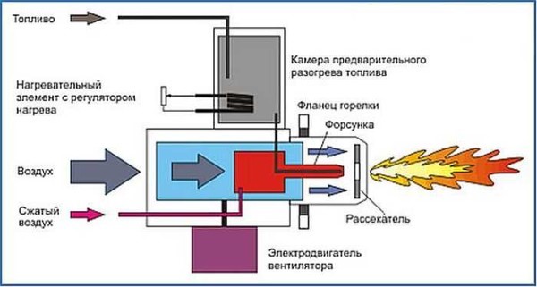
Scheme of operation of a gas burner
Fuel storage tank
Now the most interesting. For a liquid fuel boiler, a container for storing fuel is needed, and I attributed this to the shortcomings a little higher.
The calculations shown above say that the capacity is needed for several tons. There is no need to invent anything here and it is better to buy a ready-made container with all the built-in equipment: a float, a vapor outlet, a drain cock, a fuel intake kit, a pipeline for fuel output to the burner, etc.
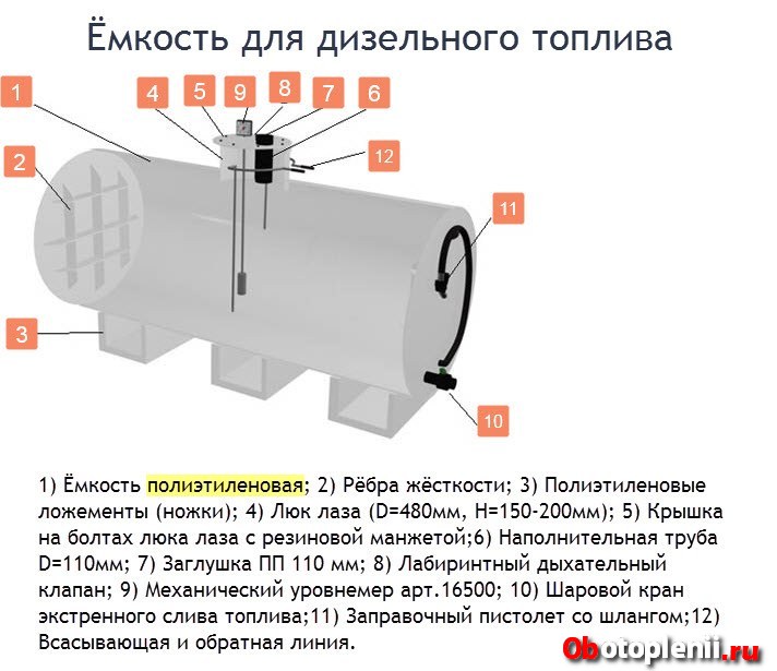
The material for containers is steel, polyethylene, fiberglass.
To install the tank, site preparation, a foundation pit, concreting and a lot of special work will be required. This needs to be understood and most likely, you will have to hire specialists.
How much fuel is needed for the season
One of the most important questions to decide is how much fuel you need for the season. Let's count.
Simplified, it is considered that:
- 1 liter of diesel fuel allows you to heat an area up to 100 meters for an hour.
- The boiler consumption is calculated as the power of the used burner multiplied by 0.1.
- And as always, 1 kW of the boiler will heat 10 square meters. meters of the house.
Let's make an approximate calculation, from the word example.
A logical question arises: Why, in comparison with the calculation according to the passport (above), this calculation above gave completely different results and where is the correct calculation?
Answer: Error in 72 liters per day. Not one diesel boiler will work 24 hours a day.
As I said, diesel boilers have very serious automation. Boiler 2/3 days, will be off, not on. Therefore, the calculation should include not 24 hours of work, but 8 hours. That is, fuel for the season is not 10449 liters, but 3483 liters.
In addition, modern boilers have technological tricks that also reduce fuel consumption, such as multi-stage burners, turbo circulation burners.
One more moment. The calculation given at the beginning of the article is based on the passport data of the boilers, which were compiled taking into account the quality of the fuel of the manufacturer's country. Also, the boiler consumption indicated in the passport is slightly underestimated, as it implies perfect insulation of the house, the temperature outside is minus 10-15˚C and is given to an already warmed-up house (heat maintenance mode).
Therefore, the correct calculation of fuel consumption for the heating season will be somewhere in the middle between 1957.5 liters according to the passport and 3483 lira according to the calculation. Remember that I thought the house was 300 meters away.
Ignition of the stove
When igniting the stove during working out, it is necessary to inspect the chimney and the lower container each time for the presence of water in them. If it is not there, then you can fill in oil (usually about 2-3 liters). It is necessary to carry out ignition with a lit wick, which is pushed into the container through the hole. The oil usually reaches operating temperature in no more than 5 minutes, but there are cases when the temperature is reached faster.
To speed up this process, you can add about 100 ml of kerosene to the used oil. The hole in the lower container must be left open for literally a couple of centimeters, and later, by sliding or moving the damper, you can regulate the combustion process.
1. Boiler building
2.1.1. Category of the boiler room for explosion and fire
fire hazard is determined in accordance with the "List of premises and buildings
energy facilities of the USSR Ministry of Energy with indication of categories for explosion and fire
and fire danger.
2.1.2. The boiler rooms must have a natural or
forced ventilation and lighting that meet the requirements of the "Sanitary
norms for the design of industrial enterprises.
2.1.3. (Excluded. Rev. No. 2)
2.1.4. The walls inside the production premises should be
smooth and painted with waterproof paint in light colors.
2.1.5. The floor of the boiler room at the service mark and
below should have an easy to clean coating.
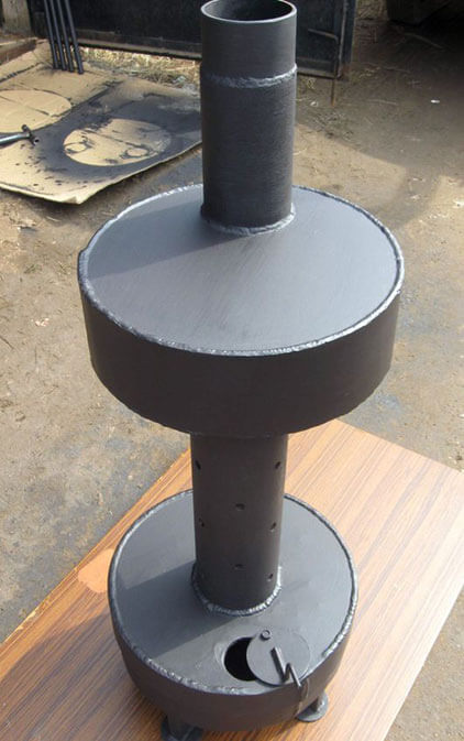
The principle of operation of the boiler
The boiler consists of two metal containers connected by a pipe. A chimney is installed in the upper part, the length of which must be at least a meter. The lower container is designed for filling mining, where the upper layer of oil is heated and turns into oil vapor. Rising, the steam goes into the perforated pipe, mixes with air, reaches the upper tank and burns. Combustion products exit through the chimney; thus, the boiler heats the room, but does not emit toxic waste.
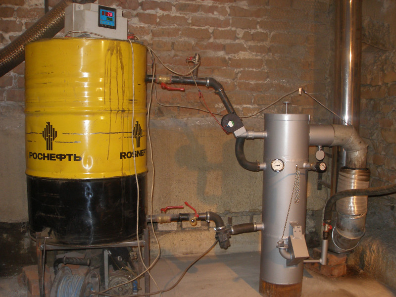
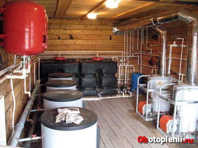
Waste oil heating boilers
A boiler without a water circuit can freely heat a garage of about 40 square meters. m. As for products with a water circuit, they allow you to maintain a comfortable temperature in fairly large rooms even in severe frosts. Moreover, fuel consumption is from 0.5 to 1 liter per hour, which makes it possible to significantly save on energy resources.
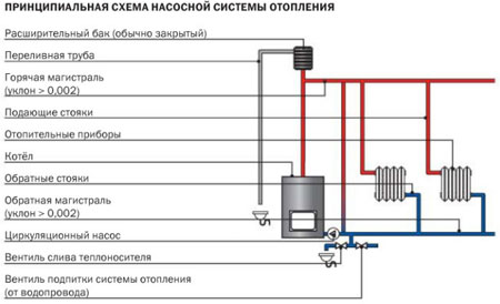
Pump heating system
Pump heating system. Circulation pump
The mining boiler can be made single-circuit or two-circuit, depending on the needs of the owner. If you use the coolant only for heating, you need a single-circuit boiler.The second option allows you to heat the room and get hot water for domestic purposes, for this there is a built-in heat exchanger in the upper tank.
Video - A variant of the furnace for working out before connecting the water jacket
The principle of operation of such a boiler is also quite simple: from the supply tank, the pump delivers exhaust to the evaporation chamber, where it heats up and turns into steam. The steam rises into the combustion chamber, mixes with air and heats the water in the circuit. Hot water enters pipes and batteries, heats the room and returns to the boiler.
As practice shows, a waste oil boiler is an efficient heating device, which is also affordable
As practice shows, a waste oil boiler is an efficient heating device, which is also affordable
As practice shows, a waste oil boiler is an efficient heating device, which is also affordable
Conclusions on consumption calculation 1
Based on the fuel consumption data, you can estimate the cost of heating for the season.
- We take the heating season of 6 months, or 180 days.
- For a house of 300 meters, a 30 kW boiler is required (1 kW per 10 meters).
- We select a boiler from the list above by 34.9 kW, which consumes an average of 12 liters of diesel fuel per day. (10.0-14.5 l).
- The maximum fuel consumption for 180 days will be 180 × 14.5 = 2610 liters.
- We understand that no one will drown at the maximum all season. We believe that for 90 days of the heating season the boiler operates at 100%, and 90 days at 50%.
- We get: 90 × 14.5 + 90 × 14.5 / 2 = 1305 + 652.5 = 1957.5 liters.
- Diesel fuel 1957.5 liters costs (retail at 38 rubles) 74385 rubles (1240 rubles per month).
In the article "Simplified calculation of the heating system" I showed the calculation of the power of the heating boiler. Below is another calculation that will show different results.