Selection of quality equipment
The battery is directly selected for a pre-purchased solid fuel type boiler and the parameters are calculated so that it can easily accumulate thermal energy to the maximum, which was generated by a direct source of the required heat.
The priority and main criterion for choosing a modern and well-thought-out heat accumulator will be the boiler itself, if its working time of heat input and power are somehow limited:
- To generate heat only for a single one-time load of any fuel and its further analysis by the installed full heating system for a whole day.
- A solar-type accumulator of a power determined and required for the stable operation of the boiler, where heat is collected exclusively during daylight hours and stably evenly or exclusively at peak use.
The main indicator for choosing a good heat accumulator is the consumer himself, when there is a need to cover the installed load of a thermal nature for a certain period of time.
It is necessary to purchase this device in accordance with individual needs, as well as the characteristics of the installed solid fuel boiler.
Design in advance what kind of heat accumulator you need so that it can fully perform the functions assigned to it and the tasks of amplifying and controlling the generated thermal energy by the boiler.
Multi-circuit heating systems with heat accumulators
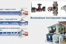
Another indisputable advantage of the accumulation tank is the potential opportunity to operate it as a hydraulic gun.
Such a function is very necessary, because due to the fact that the tank body is equipped with at least four nozzles, it becomes possible to select a coolant with the desired temperature at one or another level of the storage tank. This will make it possible to equip a high-quality circuit with a high temperature, equipped with radiators, as well as heating with low temperatures, such as underfloor heating.
However, one should not forget about pumps that have heating control circuits, since the temperature at different levels of the storage tank at different times of the day, as you know, is different. At the same time, the function of the nozzles is not limited to outlets for heating circuits. Several boiler systems equipped according to different types can be connected to one heating accumulator at once.
Wiring diagrams
There are many ways to tie a solid fuel boiler with a heat accumulator and a heating system. But they are all derived from the basic circuit shown below. With its help, it is easy to figure out how these units work in pairs, and then mount everything with your own hands.
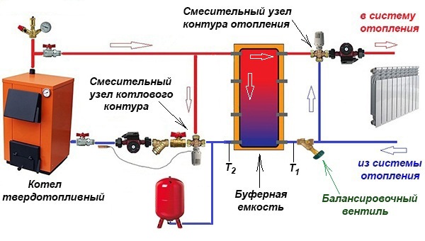
The solid fuel heat source has a traditional boiler circuit with a mixing unit, whose task is to prevent the supply of cold coolant to the boiler. Then the supply and return pipelines are connected to the buffer tank, respectively, from above and below. In the same way, a heating system, also equipped with a mixing unit, is connected to the heat accumulator. Its purpose is to maintain the required water temperature in the system, mixing in part of the hot coolant if necessary.
An important point. The actual output of the circulation pump of the boiler circuit should be slightly higher than that of the heating circuit pump set. Compliance with this condition will allow the flows inside the heat accumulator to move in the right direction (shown in the diagram with white arrows).
In fact, the network pump will be more powerful than the boiler one, and here's why.The resistance of the network of pipelines and radiators is higher than 3-5 m of a pipe from a solid fuel boiler to a heat accumulator. More power and pressure is needed for the unit to overcome this resistance. Therefore, a weaker boiler circuit pump will be able to provide a larger flow, you just need to correctly set both units. There are 2 options for resolving the issue:
- When using 3-speed pumps, you can adjust their performance by switching speeds.
- Install a balancing valve at the inlet of the return from the system to the buffer tank, with which to make adjustments.
Simultaneous heating of heaters and layer-by-layer loading of the heat accumulator is possible when the flows inside the tank move horizontally with a slight predominance from the side of the solid fuel boiler. The question arises - how to check it? The answer arises: on both inputs of the return to the tank, it is necessary to put thermometers (as in the diagram) and carry out the adjustment by switching the speed of the pumps or rotating the balancing valve
Important condition: the three-way valve of the heating network must be fully opened manually
By adjusting it is necessary to ensure that the temperature at the inlet to the heat accumulator (T1) is lower than at its outlet (T2). This means that part of the hot water goes to "charge" the battery. You can learn more about all the points from an expert by watching the video:
Alternative scheme
This scheme for tying a buffer tank and a solid fuel boiler was proposed by one of the participants in a popular forum. Its peculiarity lies in the fact that during a power outage, the operability of the circuit is maintained, although you have to pay for this with increased diameters of steel pipes. The figure below shows the connection of a heat accumulator to a closed heating system, but during installation it is better to make it open, as the author himself says.
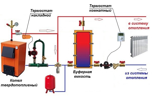
In short, the essence is this: thanks to the T-shaped input on top of the tank, the radiators are simultaneously heated and the do-it-yourself thermal accumulator is “charged”. The boiler circuit pump is controlled by a clamp-on sensor on the supply line, turning on the unit when it reaches a temperature of 60 °C. The circulation in the network depends on the room thermostat to which the network pump is connected.
Note. The proposed strapping scheme was tested by its creator on his own experience. All the details of its installation and operation are described by the author on the forum
Various types and schemes for piping a solid fuel boiler
There are many ways to connect the boiler and related equipment to the general heating system of the house. Let's consider the most common of them.
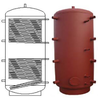
The storage tank acts as a DHW boiler
The design of the storage tank is a spiral located inside the heat accumulator. The hot coolant that is inside heats the running water of the hot water circuit. In the event of a burnout and shutdown of the boiler, the heat accumulator allows you to maintain an acceptable temperature in the room, up to 2 days. Provided that the DHW function is not used.
To control the flow and temperature of the coolant, an automatic thermal mixing device is used:
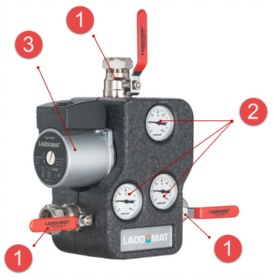
The device is also equipped with a check valve, an emergency automatic natural circulation valve (in case of a power outage), a built-in thermal valve and a fitting.
The principle of operation of the device is as follows. When the coolant reaches a certain temperature (780C), the thermal valve opens the water supply from the accumulator. The temperature is kept at a given level by regulating the cross section of the return passage from the central heating system to the bypass channel.
Scheme for connecting a solid fuel boiler to a dual-use heat accumulator:
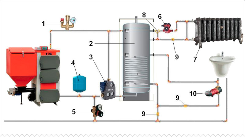 1. Security group; 2. Thermal storage tank; 3. Thermal mixer; 4. Expansion tank of membrane type; 5.System make-up valve; 6. Circulation pump of the heating system; 7. Radiators; 8. Mixing three-way valve; 9. Check valve; 10. DHW circulation pump.
Connecting a heat storage tank and a separate DHW tank
The volume of the boiler for passive heating of the DHW system depends on the number of consumers and the power of the equipment used. When piping pellet boilers, it is not recommended to use polypropylene materials and structures. The temperature of the heat exchanger at the outlet at peak loads often exceeds the performance of pipes made of polymer materials.
Piping a solid fuel boiler with a separate hot water boiler:
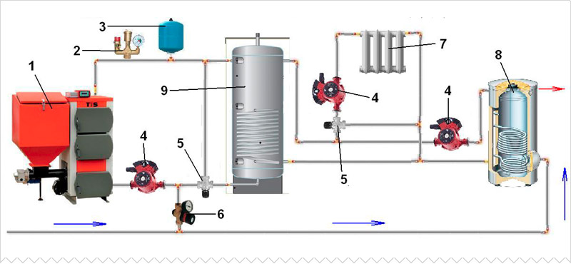 1. Boiler. 2. Security group 3. 4. Expansion membrane tank. 5. 6. Pump. 7. Mixing three-way valve. 8. System make-up valve. 9. Radiator. 10. Domestic hot water boiler for indirect heating. 11. Thermal storage tank.
Parallel connection of two heating boilers
In order to extend the service life and evenly distribute the resources used, users often combine two different types of heating sources into a single heat supply scheme. In this case, the main source of heat in winter is a solid fuel boiler. The electric boiler is switched on in emergency mode and during the summer months when it is used to heat water.
Piping scheme for a solid fuel heating boiler with parallel electrical connection:
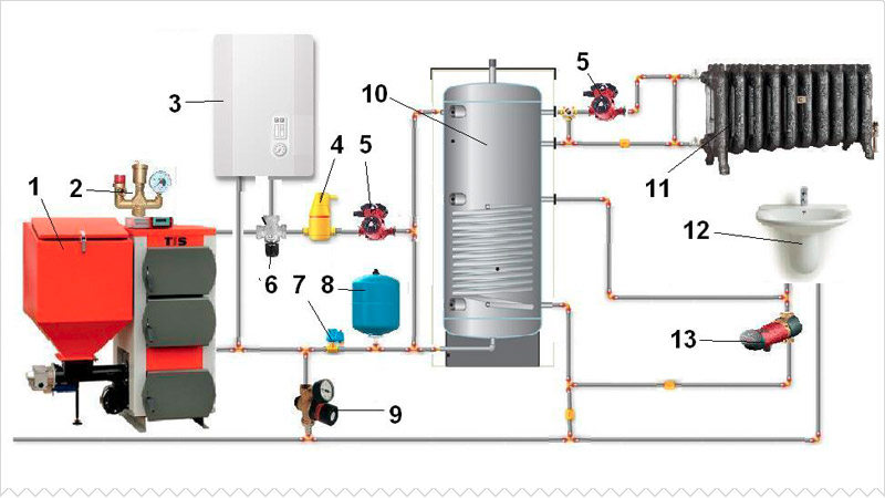 1. Pellet boiler. 2. Group of safety of system of heating. 3. Alternative boiler (electric or gas). 4. Separator to remove air from the system. 5. Circulation pump. 6. Manual three-way mixing valve. 7. Dry running protection valve. 8. Expansion tank. 9. Valve for feeding the system with water. 10. Heat accumulator. 11. Washbasin. 12. 13. DHW pump.
A heating system based on a pellet boiler is quite complex and requires careful tuning. Before performing installation work, carefully read the instructional material provided by the manufacturing companies.
Heat accumulator calculation
A container for the accumulation of thermal energy can be either purchased ready-made or made independently. But a natural question arises: what capacity should the tank be? After all, a small tank will not give the desired effect, and too much will cost a pretty penny. The answer to this question will help to find the calculation of the heat accumulator, but first you need to determine the initial parameters for the calculations:
- heat loss of the house or its quadrature;
- duration of inactivity of the main heat source.
Let us determine the capacity of the storage tank using the example of a standard house with an area of 100 m2, which requires an amount of heat of 10 kW to heat. Assume that the net downtime of the boiler is 6 hours, the average temperature of the heat carrier in the system is 60 °C. Logically, during the period of time while the heating unit is idle, the battery must supply 10 kW to the system every hour, for a total of 10 x 6 = 60 kW. This is the amount of energy that should be accumulated.
Since the temperature in the tank should be as high as possible, for calculations we will take a value of 90 ° C, domestic boilers are still unable to do more. The required capacity of the heat accumulator, expressed in mass of water, is calculated as follows:
- Q is the amount of accumulated thermal energy, in our case it is 60 kW;
- 0.0012 kW / kg ºС is the specific heat capacity of water, in more familiar units of measurement - 4.187 kJ / kg ºС;
- Δt is the difference between the maximum temperature of the coolant in the tank and the heating system, ºС.
So, the water accumulator should contain 60 / 0.0012 (90 - 60) = 1667 kg of water, which is approximately 1.7 m3 in volume. But there is one point: the calculation is made at the lowest temperature outside, which happens infrequently, excluding the northern regions.In addition, after 6 hours, the water in the tank will cool down only to 60 ºС, which means that in the absence of cold weather, the battery can be “discharged” further until the temperature drops to 40 ºС. Hence the conclusion: for a house with an area of 100 m2, a storage tank with a volume of 1.5 m3 is enough if the boiler is inactive for 6 hours.
Requirements for an uninterruptible
To find out which uninterruptible unit is suitable for a gas boiler, you need to decide in advance on the requirements that apply to the device. It will help to get acquainted with the main indicators of the UPS, which characterize the efficiency of its work. Some of them:
- Active and apparent (taking into account the reactive component) power, defined as the product of the supply voltage and the current in the load.
- The coefficient of harmonic distortion, indicating the quality of the output voltage - the deviation of the shape of the sinusoid from the ideal form.
- The presence of an external battery that allows not to interrupt the operation of the boiler in the absence of mains power for several hours.
- Duration of offline operation.
- Limits of permissible input voltage fluctuations in Volts.
The duration of work from the battery depends to a greater extent on its capacity.
When, according to the operating conditions of the boiler equipment, long interruptions in the power supply are expected, it should be possible to connect additional batteries. It is also desirable that the purchased device has the function of automatically monitoring the state of the power supply and restoring normal power mode.
Connecting the heat accumulator piping to the heating system
As a general rule, the buffer tank is connected to the heating system in parallel with the heating boiler, therefore this scheme is also called the boiler piping scheme.
Let us give the usual scheme for connecting TA to a heating system with a solid fuel heating boiler (to simplify the scheme, shutoff valves, automation, control devices and other equipment are not indicated on it).

Simplified heat accumulator piping scheme
This diagram shows the following elements:
- Heating boiler.
- Thermal accumulator.
- Heating devices (radiators).
- Circulation pump in the return line between the boiler and the heater.
- The circulation pump in the return line of the system between the heating devices and the TA.
- Heat exchanger (coil) for hot water supply.
- Heat exchanger connected to an additional heat source.
One of the upper pipes of the tank (pos. 2) is connected to the boiler outlet (pos. 1), and the second one is connected directly to the supply line of the heating system.
One of the lower branch pipes of the HE is connected to the boiler inlet, while a pump (pos. 4) is installed in the pipeline between them, which ensures the circulation of the working fluid in a circle from the boiler to the HE and vice versa.
The second lower branch pipe THAT is connected to the return line of the heating system, in which a pump (pos. 5) is also installed, which provides the supply of heated coolant to the heaters.
To ensure the functioning of the heating system in the event of a sudden power outage or failure of the circulation pumps, they are usually connected in parallel to the main line.
In systems with natural coolant circulation, there are no circulation pumps (pos. 4 and 5). This significantly increases the inertia of the system, and at the same time makes it completely non-volatile.
The DHW heat exchanger (pos. 6) is located in the upper part of the HE.
The location of the additional heat exchanger (pos. 7) depends on the type of heat input source:
- for high-temperature sources (heating element, gas or electric boiler) it is placed in the upper part of the buffer tank;
- for low-temperature ones (solar collector, heat pump) - at the bottom.
The heat exchangers indicated in the diagram are optional (pos.6 and 7).
Principle of operation
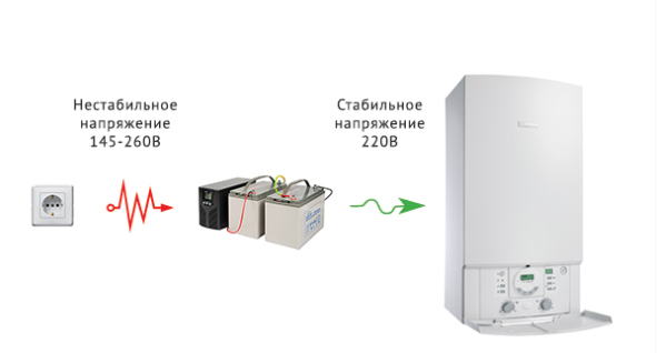 The essence of the operation of the device in relation to boiler equipment is no different from the principle of protecting other electrical devices. It is expressed in the adoption of special measures to stabilize the voltage and the ability to maintain it for some time at the required level. For these purposes, a UPS is used for boilers with an external battery connected, the direct voltage from which is converted into alternating voltage by means of an electronic inverter.
To smooth out voltage fluctuations in the network or protect against its short-term loss, the principle of double conversion is used, which consists in the following:
- The corrected AC voltage is applied to the mains filter, which smooths out sharp fluctuations by limiting high-frequency harmonics.
- It enters the diode bridge, which converts the variable component to a constant.
- If necessary, part of the rectified current is spent on the charging circuit of the standby battery used in a situation where the voltage disappears for a long time.
- The main part of it goes to the inverter, in which the inverse conversion of the constant component into a variable is carried out.
- The stabilized voltage thus obtained is suitable for powering a solid fuel or gas boiler.
Advantages and disadvantages of buffer capacity
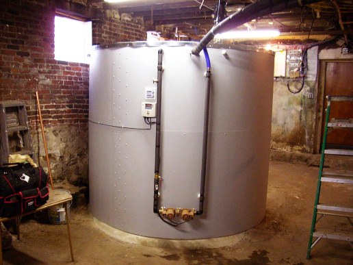
Boiler buffer tank
The main advantages of a heating system with a heat accumulator include:
- the maximum possible increase in the efficiency of a solid fuel boiler and the entire system while saving energy resources;
- ensuring protection of the boiler and other equipment from overheating;
- ease of use of the boiler, allowing it to be loaded at any time;
- automation of the boiler operation through the use of temperature sensors;
- the ability to connect several different heat sources to the HE (for example, two boilers of various types), ensuring their integration into one heating system circuit;
- ensuring a stable temperature in all rooms of the house;
- the possibility of providing domestic hot water without the use of additional water heating devices.
The disadvantages of heat accumulators for the heating system include:
- increased inertia of the system (much more time passes from the moment the boiler is ignited until the system enters the operating mode);
- the need to install TA near the heating boiler, for which a separate room of the required area is required in the house;
- large dimensions and weight, causing the complexity of its transportation and installation;
- a rather high cost of industrially produced HE (in some cases, its price, depending on the parameters, may exceed the cost of the boiler itself).
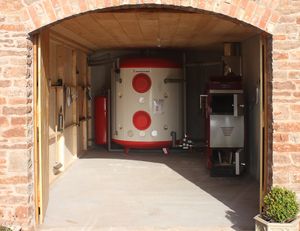
An interesting solution: a heat accumulator in the interior of the house.
In the interior 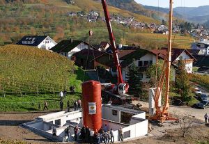 Installation
 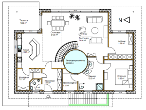 1st floor
 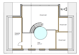 Attic
Attic 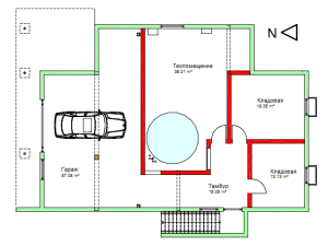 Basement
 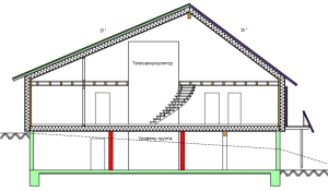 Section
The use of a heat accumulator is economically beneficial not only for solid fuel boilers, but also for electric or gas heating systems.
In the case of an electric boiler. TA turns on at full capacity at night, when electricity tariffs are much lower. During the day, when the boiler is turned off, the space is heated using the heat accumulated during the night.
For gas boilers, savings are achieved through the alternate use of the boiler itself and TA. At the same time, the gas burner turns on much less frequently, which ensures less gas consumption.
It is undesirable to install a heat accumulator in heating systems where fast and or short-term heating of the room is required, since this will be hampered by the increased inertia of the system.
3 comments
Instead of the heat accumulators indicated in the article, it is possible to successfully use storage water heaters with a capacity of 200 liters or more, connected in parallel.Heat accumulators are connected to the heating boiler after regular heating of the house and (or) the threat of overheating of the boiler. It is much cheaper than the options offered. In addition, heating elements of water heaters can be used during a break in the operation of the boiler, for example, at night. This is beneficial with a multi-tariff meter. The only thing is that when using ethylene or propylene-glycol as a coolant, the magnesium rod installed to soften the water must be removed from the water heaters. Such a system has been working for me for four years, allowing even in winter to heat a solid fuel boiler once a day. In severe frosts (from -27) twice a day. Three storage water heaters with a capacity of 200 liters each serve as a heat accumulator. Each water heater cost me 9700.
Connecting professional advice
In order to correctly and efficiently implement a private heating system based on any solid fuel boiler, you can connect a heat accumulator in several ways. They are quite common among professional craftsmen, but you can learn this on your own, since there is nothing complicated and supernatural in these schemes.
Advice! Consider the fact that the cost of work directly depends on the basic principle of building a system of constant fuel circulation in the boiler.
Heat accumulator connection diagram
With liquid mixing
The scheme for connecting a heat accumulator to a solid fuel boiler of a common type is extremely clear. Easily and affordably used in the piping of permanent heating systems, which are based on the circulation of a simple gravity type of fuel in the boiler. In this situation, this happens:
- During the heating of the set volume of water in the heat exchanger of the device itself, its circulation begins throughout the system of the installed pipeline, which passes through the boiler valve.
- When the temperature set by the user is reached, the built-in valve actively starts to work and accordingly maintain the pre-set value, gradually mixing only cold water from the boiler itself.
- At this moment, hot water from the installed unit is poured into the tank - this is how the heat accumulator is charged.
- For all the time that can only be determined by the boiler tank, the fuel burns out completely.
- Starts the reverse process, which consists of supplying water to small radiators. Temperature stability is maintained all the time.
- When the direct source of the required heat cannot maintain stable heating of the water in the heat accumulator tank, the installed valve closes promptly and reliably, and the system instantly returns to its original state.
If there is no power supply or the circulation pump fails, the boiler immediately goes into a special buffer mode, which allows the entire system to work only on the check valve.
Connecting a heat accumulator to a solid fuel boiler
The collected water, which has heated up to this point in the boiler itself, then actively enters the installed tank. Then she goes to several heating radiators. This continuous process ensures that the water is heated smoothly and that the high temperatures drop gently.
Advice! In order for the heating circuit to function at its best, the heat accumulator must be mounted high enough so that there is no contact with the heating radiators.
With hydraulic distribution
A system of this type is sold for almost every boiler model. Due to them, it is possible to provide for an uninterrupted and stable supply of electricity. In order for the entire thought-out system to work correctly and smoothly, it is worthwhile to correctly and clearly provide for a source of stable and nutritious nutrition.
It is possible to implement this principle: the installed boiler will serve only as a special container, which to the maximum stabilizes the temperature of a sufficiently large volume of water necessary for comfort in the room. This makes sense in the case when it is necessary to immediately supply power to several private heating circuits.
Connecting a heat accumulator to a solid fuel boiler of this type has also found wide application among modern users and developers.
Which heat accumulator connection scheme to choose depends solely on the individual needs of the owner of the house and those living there. Here you need to weigh all the advantages and disadvantages, as well as take into account many factors that can significantly affect the final choice.
Quite a lot depends on the area that will be heated with a solid fuel boiler; used elements and assemblies of the entire installation; the calculated number of contours that will be made in the harness; the presence of a well-thought-out system of hot stable water supply of the entire room.
Properly organizing a wiring diagram is a difficult task that requires increased concentration and the right approach. If there is no confidence in your knowledge, it is better to entrust the process to experienced and qualified specialists.