Test of endurance
Intake fittings (faucets, valves, gate valves) in most cases are made of metal by casting. During the production of products on the body can be formed:
- cracks;
- sand or gas shells;
- porosity;
- material inhomogeneity.
In order to identify and eliminate these defects, check valves are checked for strength and density of the material used for manufacturing.
How the study is done
The quality of shut-off valves is made using a special stand, on which are installed:
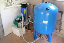
- a device that supplies water to an armature and creates a certain pressure. Most often, such a device is a manual or electric pump;
To obtain accurate results, a test pressure is created in the system, which is 1.5 - 2 times higher than the nominal parameter, that is, set by the technical documentation.
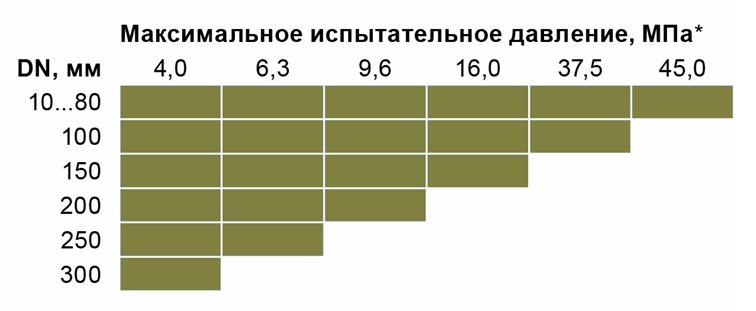
Dependence of test pressure on valve parameters
- tested fittings;
- pressure gauge (required to determine the pressure indicator in the system);
- 5. 6. the control valves required for the test;
- plug, supplemented with a tube;
- a container with water, a beaker and a special nozzle for a beaker.
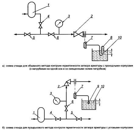
The scheme of the stand for testing the strength of the material
The valves to be checked are supplied with water at the specified pressure and at normal air temperature. The test time is 25 - 30 seconds (if necessary, the time can be increased). The test results are evaluated by an external inspection of the product by a qualified specialist.
Test Results
The test of shut-off valves is considered successfully passed if not detected (in accordance with GOST R 53402-2009):
- mechanical damage and deformation of the metal;
- leaks;
- “sweating” of metal (moisture protrusions on the surface of the reinforcement);

The appearance of moisture on the surface of the reinforcement
drop in pressure gauge.
To get more accurate results, during the test, the specialist can tap the reinforcing product with a small hammer (weighing no more than 1 kg).
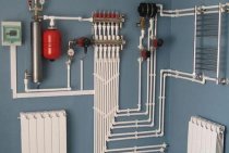
Pipeline testing
"First Mounting Company" provides services for hydraulic and pneumatic testing of pipelines for strength, density and tightness. After the installation of process piping is completed, testing is always required before commissioning. Our company tests both pressure and non-pressure pipelines.
Strength testing of technological pipelines takes a little time, since holding at the test pressure usually does not take more than 20 minutes. Testing process pipelines for density and tightness takes more time, and is usually regulated by the project. Usually this time is from half an hour to several hours. An integral part of the installation of process pipelines are hydraulic and pneumatic tests, and in the case of pressure pipelines, these tests are mandatory.
Before testing, the pipeline is degreased and purged with gas to dry, and purging is also carried out after hydraulic testing of the pipeline to drain the remaining water.
Hydraulic testing of pipelines
Hydraulic tests are carried out if there is a high working pressure in the pipeline to be installed (over 50 bar). The pressure rise in the technological pipeline during hydraulic tests is carried out using manual or electric pumps.
The hydraulic testing process has several stages:
- connection to the circuit of the technological pipeline of the hydraulic pump;
- installation at the inlet and outlet of the pressure gauge circuit;
- filling the process pipeline with purified water;
- creation of test pressure by a hydraulic pump;
- keeping the process pipeline under the required pressure;
- pressure relief to the working one, followed by inspection of the tested section of the pipeline for leaks;
- depressurization to zero and draining of water from the process pipeline;
- removal of equipment (hydraulic pump, plugs and pressure gauges);
- drying process pipeline with gas.
The technological pipeline is considered to have passed hydraulic tests if the pressure drop did not exceed ten percent of the test one, or was not recorded at all. No leaks or sweating were found in the welds and flanged joints. In case of unsatisfactory results, the detected defects are eliminated, and the test is repeated.
Hydraulic testing of technological pipelines in the cold season and the presence of negative temperatures is carried out, providing everything necessary for the non-freezing of water.
Hydraulic tests of water supply pipelines, as well as hydraulic tests of non-pressure pipelines, are carried out with a minimum pressure to check the strength and tightness of the joints. Testing of pressure pipelines is carried out with the pressure provided for by the project.
Pneumatic testing of pipelines
Pneumatic testing of technological pipelines is carried out at a low operating pressure of the pipeline, which saves time on drying after testing. For some objective reasons, it is impossible to carry out hydraulic tests, or the project provides for pneumatic tests of pipelines.
It is necessary to test pipelines under the supervision of the facility manager in accordance with the project and in compliance with safety regulations.
Pneumatic tests of technological pipelines are usually carried out as a single circuit, together with fittings (with the exception of valves for relieving excess pressure). If the design of the pipeline does not allow this, or the project provides otherwise, then the pipeline is divided into conditional lines or sections and each section is tested separately. At the place of gas supply for testing and the place of completion of the technological pipeline, pressure gauges must be installed, all leaks are silenced with special plugs.
Pressure gauges used in pipeline testing must be calibrated. The accuracy class of pressure gauges must be at least 1.5 and the case diameter must be at least 100 mm, as well as a scale exceeding the test pressure.
Pneumatic testing of gas pipelines
Posts: 12 Registered: 01.10.12
Good day! Tell a novice gas service.
When installing gas supply for internal, external (with standard and non-standard connection), the price e16-8-1 is applied - laying gas supply pipelines from steel pipes DN15 mm (well, other diameters, respectively) + additional price e19-15-1 - Pneumatic testing of gas supply pipelines - so I used the previous estimator, and I prove that we double the work, which in E16-8-1- is already included in the work “Blowing with compressed air”.
When repairing, respectively, the price is also p15-141-1 - pipe laying + p15-153-1 - pneumatic test.
I also found a handwritten extract (apparently on the basis of which an additional pneumatic test was taken):
1) “Underground steel and polyethylene gas pipelines of all pressures, as well as overground and internal steel gas pipelines of low and medium pressure, are tested for strength and tightness by air.”
2) “Pressure testing (saponification of joints, pumping up pressure) = pneumatic test (saponification, blowing out debris, scale)
3) “Purge is not included in the pneumatic test (done when the gas pipeline is tested)
Tell me who is right and on what basis? (maybe it was somewhere in the Central Organ or some other reliable sources?
Posts: 4475 Registered: 06.12.07
Posts: 1204 Registered: 11/16/10
Posts: 88Registered: 05.02.08
Posts: 158Registered: 05/29/15
We have a gas pipeline that was built 1.5-2 years ago, but has not been put into operation. It is necessary to re-pneumatic test the gas pipeline. Gas pipeline internal and street.
I did not make the estimate for the construction, but I have it
Internal gas pipeline: 15,20,25 and 50 (collector) diameter. the following standards were applied: E16-8-1 (2.3) - for 15.20 and 25 diameters, and for 50 - E16-9-12. For these positions, a pneumatic test was separately included - E19-15-1 for 15,20,25 diameters, and for 50 diameters, a pneumatic test was also viscous + a compressor (SN205-102) with a machine hour half less than a person .hour.
1. How to take a pneumatic test? for these diameters? Just E19-15-1?
2. and what about this 50 diameter (internal)? And is it possible to add a compressor to the norm in such a way where it is calculated by man hours that a hand pump is used?
Through the street pipeline. diameters: 57,76,89 and 108 the norms that were used - EN22-9-1 (2.3) There, as part of the work, there is already a pneumatic test.
3. How to apply the pneumatic test to these diameters? I saw somewhere that they take the same rate as for laying steel pipes, but using the coefficient. 0.1 to the labor costs of builders and 0.3 to the operation of machines and mechanisms. Maybe it was somewhere in the CO?
__________________________________________________________________________________
and further.
valve replacement work. diameter 32mm
I use RN16-26-1 - this is Installation of steel gate valves and check valves with a diameter, mm, up to 50
but after installing the valve, a pneumatic test of the gas pipeline with a diameter of 32mm is necessary. What to use for testing?
Hose work
The gas stove can be connected independently using a rubber flexible hose, which is most often used for the following reasons:
- It is quite safe, because thanks to it the stove model can be moved in the kitchen up to 1.5 meters.
- If you randomly touch the plate and move it from its place, then this will not threaten you with anything.
- This type of connection is considered very durable, because such hoses can last up to 10 years.
- Their cost will be affordable for every owner.
So, let's get to work. Choose the length of the hose according to your own preference, but it is better to take a long product (from 3 m). Be sure to watch the color of the label on the pipe - you need a metal braided hose with a yellow label, because the other colors (red and blue) indicate that this product is intended for water. Such hoses will absolutely not suit you, because a special hose is required to connect the gas stove. Now see if the size of the inlet on the hose matches the size of the inlet on the pipe. If the outlet of the hose does not match the dimensions of the outlet of the pipe, then buy an adapter.
1 Purpose of Christmas trees
Christmas tree fixtures have main use cases:
- well sealing;
- formation of a withdrawal of products;
- well flow rate adjustment;
- access directly to the bottom of the well;
- manipulations in the annulus (carrying out sampling operations without stopping production, changing pressure and temperature in the well bottom).
X-mas tree fittings are used at excess pressure under the influence of large loads. The design is used in the case when there is a possibility of exposure to an aggressive environment in wells. Often it is used for high abrasive loads, when there are a large number of associations of various rocks in the water.
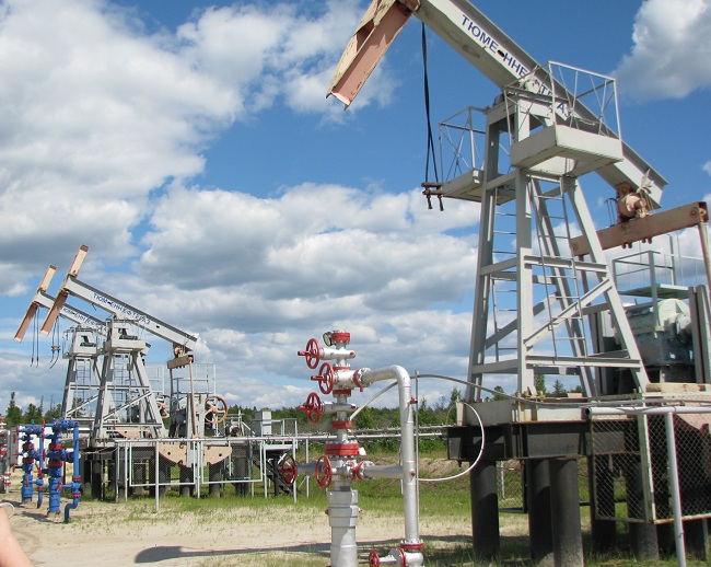
Use of Christmas trees for oil production
It is necessary to use the system taking into account the fact that this type of equipment must have high strength and durability, without which production will be inefficient. The main choice of application of this equipment is the production of gas and the laying of oil pipelines.
1.1 Varieties
Gosstandart has defined several types of Christmas trees:
- Tee/Cross (selection depends on tree configurations). The side outlets are connected to collection and metering plants using flow lines.
- Double-row or single-row (the number of rows of pumping products descending into the well).
- Equipped with valves or faucets.Gate valves are used for oil wells, and valves are used for gas wells.
Depending on the structural and strength characteristics, the fountain piping is classified according to:
- working pressure. Standard piping is designed for a pressure of 7-105 MPa. Valves designed for the highest possible pressure are used for very deep wells, or in which abnormally high reservoir pressure (AHRP) has been recorded.
- The size of the bore section of the trunk (50-150 mm). The design with a bore diameter of 100 to 150 mm is designed for high-rate oil and gas wells.
When choosing a material for the manufacture of a device, it is necessary to take into account the properties of the medium, which cannot be dispensed with. In a fire and explosive environment, it is not recommended to opt for cast iron parts.
Typical schemes and table numbers are in the price list of the Ministry of Mechanical Engineering.
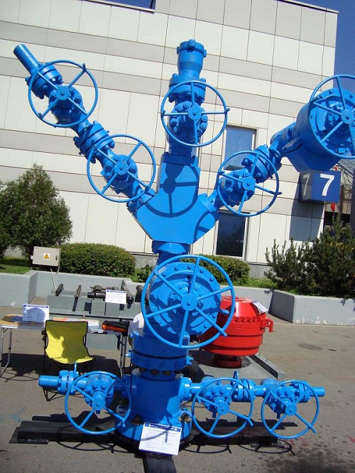
Fountain tree EF6D-100/80×70KZ
Typical types of fittings include various gate valves, taps, valves, gates. Special piping consists of pressure reducing valves, locks and valves for catalyst pipelines and standby fittings.
When ordering a typical connection to manufacturers, it is necessary to inform its symbols from a specific scheme.
Safety measures when connecting newly constructed gas pipelines to existing ones
Work on connecting newly constructed gas pipelines to existing ones must be carried out in accordance with the "Safety Rules in the Gas Industry", the rules for technical operation and safety in the gas industry, in force in the republic or department. In accordance with the above rules, it is allowed to carry out work on connecting newly built gas pipelines to the existing ones by a specialized team subordinate to the management, trust, office operating the gas facilities of the city (settlement). The head of the team is appointed from among the engineering and technical workers trained in the rules for conducting gas hazardous work and who have passed exams when testing knowledge of these rules.
The connection of newly built gas pipelines to the existing ones is carried out according to special permits from the management of the trust, the office of the gas economy on the basis of acts of acceptance into operation of the gas pipeline. An organization submitting a newly installed gas pipeline for connection shall transfer technical documentation to the management, trust, gas facilities office, including diagrams for connected gas pipelines indicating all branches, pipe diameters, valves, condensate collectors and other structures.
Before tie-in, underground and above-ground gas pipelines, regardless of the operating pressure, are subject to control pressure testing with air at a pressure of 2000 mm of water. Art. The pressure drop must not exceed 10 mm of water. Art. at 1 o'clock
Tapping into an existing gas pipeline is carried out with and without a decrease in gas pressure. At a reduced pressure during the tie-in in the gas pipeline, a pressure of 40 to 100 mm of water is maintained. Art. A manometer is installed to control the pressure. Tapping into existing gas pipelines without reducing the gas pressure in them is allowed when using a special device that prevents gas from escaping to the outside.
Before starting work, the team leader introduces all workers to their duties and the sequence of operations for connecting gas pipelines, then re-instructs the workers on safety precautions for the work performed by each member of the team at the facility.
The head of the team checks the presence of excess air pressure in the connected gas pipeline, the suitability of the pit for tie-in work, the presence and serviceability of locking devices on the inlets and risers, valves, valves, plugs and plugs on the gas inlets into the room.
All valves and faucets must be closed and plugged.Plugs installed on gas pipelines are calculated for the maximum gas pressure in the gas pipeline. They must have shanks protruding beyond the flanges.
Connection of inputs to existing gas pipelines is allowed only when the internal gas pipelines are disconnected after the valve, - a valve at the input with the installation of a plug and if there is a device (plug, valve) for venting air and gas-air mixture from the underground part of the gas pipeline.
Newly built gas pipelines are connected to the existing ones with the use of welding, without it - to disconnecting devices installed in advance when laying street gas pipelines. It is possible to connect by welding to gas pipelines of low, medium and high pressures at reduced gas pressure; without reducing the pressure and after shutting down the existing gas pipeline and completely releasing it from the gas.
Connection at reduced pressure is associated with a disruption in the gas supply to a significant number of consumers, therefore, work is carried out at night, as a result of which safety conditions are violated.
Pictures for this chapter:
| Device for connecting branches to existing gas networks without reducing gas pressure |
—
CAUTION 1
пÑеÑÑовка Ð Ð Ð Ð μm Ð Ð Ð Ð Ð Ð Ð Ð Ð Ð Ð Ð Ð Ð Ð ÐμÐ Ð Ð ÐμÐ Ð Ð Ð Ð Ð Ð ÐμÐ Ð Ð Ð Ð Ð Ð ÐμÐ Ð Ð Ð Ð Ð ÐμÐ Ð Ð Ð Ð Ð Ð ÐμÐ Ð ² ÑоÑмаÑ. Ð Ð Ð Ð Ð Ð Ð Ð Ð Ð Ð Ð Ð Ð Ð Ð Ð Ð Ð Ð Ð Ð Ð Ð Ð Ð Ð Ð Ð Ð Ð Ð Ð Ð Ð Ð Ð Ð Ð Ð Ð Ð Ð Ð Ð Ð Ð Ð Ð Ð ññññññ.
a
RESEARCH опÑеÑÑовке аÑмаÑÑÑÑ Ð½ððððððð ðððððððññññññð¿ðððð ° °ð μμμμμμμμμð¾¾¾²²²²²²²²²²²²²²² ° - ññððμ½½ð' ((ñð¸ð³.
a
|
СÑема ÑÑенда гÑÑпповой опÑеÑÑовки гÑÑпповой опÑеÑÑовки гÑÑпповой a |
СУ-7 R. ROOM гÑÑÐ¿Ð¿Ð¾Ð²Ð°Ñ 200 roubles. 200 roubles.
a
|
ЧеÑÑеж a |
Ð Ð Ð Ð Ð Ð Ð Ð Ð Ð Ð Ð Ð Ð Ð Ð Ð Ð Ð Ð Ð Ð Ð Ð Ð Ð Ð Ð Ð Ð Ð Ð Ð Ð Ð Ð Ð Ð Ð Ð Ð Ð Ð Ð Ð Ð Ð Ð Ð Ð Ð Ð Ð Ð Ð Ð Ð Ð Ð Ð Ð Ð Ð Ð Ð Ð Ð Ð Ð Ð Ð Ð Ð Ð Ð Ð Ð Ðμ ¸ Ð ° Ð Ð Ð Ð Ð Ð Ð Ð Ð Ð Ð Ð Ð Ð Ð Ð Ð Ð Ð Ð Ð Ð Ð Ð Ð Ð Ð Ð Ð Ð Ð Ð Ð Ð Ð Ð Ð Ð Ð Ð Ð Ð Ð Ð Ð Ð Ð Ð Ð Ð Ð Ð Ð Ð Ð Ð Ð Ð Ð Ð Ð Ð Ð Ð Ð Ð Ð Ð Ð Ð Ð Ð Ð Ð Ð Ð Ð Ðμ °ÑÑ, оÑÑеки, панеи, вÑполненнÑе пÑÑем опÑеÑÑовки аÑмаÑÑÑÑ.
a
Ð Ð · Ð ° виÑимоÑÑи Ð¾Ñ ÐºÐ¾Ð »Ð¸ÑÐμÑÑвР° и моÑноÑÑи коÑл оР° гÑÐμгР° Ñов мР° ÑÑÐμÑÑкР° Ñ Ð'оР»Ð¶Ð½Ð ° Ð ± ÑÑÑ Ð¾Ð ± оÑÑÐ'овРÐ1 Ð ° РоРРРРРРРРРРРРРРРРРРРРРРРРРРРРРРРРРР¸ ññÐ𠾸¸¸ðð Ð Ð Ð Ð Ð ñ Ð Ð Ð Ð Ð Ð Ð Ð Ð Ð Ð Ð Ð Ð Ð Ð Ð Ð Ð Ð Ð Ð Ð Ð Ð Ð Ð Ð Ð Ð Ð Ð Ð Ð Ð Ð Ð Ð Ð Ð Ð Ð Ð Ð Ð Ð Ð Ð Ð Ð Ð Ð Ð Ð Ð Ð Ð Ð Ð Ð Ð Ð Ð Ð Ð Ð Ð Ð Ð Ð Ð Ð Ð Ð Ð Ð Ð Ð Ð Ð ñ ´Ð»Ñ опÑеÑÑовки аÑмаÑÑÑÑ.
a
Ð Ð Ð Ð Ð Ð Ð Ð Ð Ð Ð Ð Ð Ð Ð Ð Ð Ð Ð Ð Ð Ð Ð Ð Ð Ð Ð Ð Ð Ð Ð Ð Ð Ð Ð Ð Ð Ð Ð Ð Ð Ð Ð Ð Ð Ð Ð Ð Ð Ð Ð Ð Ð Ð Ð Ð Ð Ð ð Ð Ð Ð Ð Ð Ð Ð Ð Ð Ð Ð Ð Ð Ð Ð Ð Ð Ð Ð Ð Ð Ð Ð Ð Ð Ð Ð Ð Ð Ð Ð Ð Ð Ð Ð Ð Ð Ð Ð Ð Ð Ð Ð Ð Ð Ð Ð Ð Ð Ð Ð Ð Ð Ð Ð ½ Ð Ð Ð Ð Ð Ð Ð Ð Ð Ð Ð / Ñм2, и вакÑÑм-наÑÐ¾Ñ Ð ÐÐ-6. пÑеÑÑÐ¾Ð²ÐºÑ 100% Ð ¡ñð¸ððÐ ° Ð ° Ð ° Ð ° Ð Ð Ð Ð Ð Ð Ð Ð Ð Ð Ð Ð Ð Ð Ð Ð Ð μl изделий. СÑÐμнÐ' ÑоÑÑÐ¾Ð¸Ñ Ð¸Ð · нР° ÑоÑÐ ° Ñ ÑÐ »ÐμкÑÑоÐ'вигР° ÑÐμл Ðμм, ÑÐ ° Ð¼Ñ Ñ Ð¼ÐμÑÐ ° ниР· мом повоÑоÑÐ °, кÑонÑÑÐμйнов, Ð · Ð ° жимнÑÑ Ð²Ð¸Ð½Ñов и бака оÑÑÑойником.
a
|
Ð Ð Ð Ð Ð Ð Ð μñ Ð Ð Ð Ðμñ Ðμñ Ðμñ Ðμñ Ðμñ | ROOM. a |
Ð ÐμÐ¼Ð¾Ð½Ñ Ð ° ÑмР° ÑÑÑÑ Ð¾Ð¿Ð¸ÑÐ ° ннÑм ÑпоÑоР± ом можÐμÑ Ð ± ÑÑÑ ÑÐμкомÐμнÐ'овР° н Ð'Ð »Ñ ÑÑÑÐ ± опÑовоÐ'ов Ñ Ñол оÐ'ной ÑÑÐμÐ' ой. пÑеÑÑÐ¾Ð²ÐºÑ Ð ²ÐððñðÐðÐðÐ ° ¿ðððððÐμðððððð ðððнннннÐμÐμÐμоÐμððð¾¾¾ðÐð μμоðÐμ ñ ñ
a
Ð Ð Ð Ð Ð Ð Ð Ð Ð Ð Ð Ð Ð Ð Ð Ð Ð Ð Ð Ð Ð Ð Ð Ð Ð Ð Ð Ð Ð Ð Ð Ð Ð Ð Ð Ð Ð Ð Ð ²Ð Ð Ð Ð Ð Ð Ð δÐ Ð ² Ð ²ÐðÐðÐðºðоов Ð ÐμнРРРРÐμÐ Ð Ð Ð Ð Ðμ Ð Ðμ Ð Ðμð½¸ðμμμ. RESEARCH опÑеÑÑовке аÑмаÑÑÑÑ Ð²ÐµÑновном Ð Ð Ð Ð Ð Ð Ð Ð Ð Ð Ð Ð Ð ° Ð Ð Ð Ð Ð Ð Ð Ð Ð Ð Ð Ð Ð Ð Ð Ð Ð Ð Ð Ð Ð Ð Ð · Ð ° Ð Ð Ð Ð Ð Ð Ð Ð Ð Ð Ð Ð Ð Ð Ð Ð Ð Ð Ð Ð Ð Ð Ð Ð Ð Ð Ð Ð Ð Ð Ð Ð Ð Ð Ð Ð Ð Ð Ð Ð Ð Ð Ð Ð Ð Ð Ð Ð Ð Ð Ð Ð Ð Ð Ð Ð Ð Ð Ð Ð Ð Ð Ð Ð Ð Ð Ð Ð Ð Ð Ð Ð Ð Ð Ð Ð Ð Ð Ð Ð Ð Ð Ð Ð Ð Ð Ð Ð Ð Ð Ð Ð Ð ° Рвление. 45 rub.
a
|
Ð Ð Ðμð½Ð Ð Ð ÐμÐ Ð Ð Ð Ð Ð Ð Ð Ð Ð Ð Ð Ð Ð Ð Ð Ð Ð Ð Ð Ð Ð Ð Ð Ð Ð Ð Ð Ð Ð Ð Ð Ð Ð Ð Ð Ð Ð Ð Ð · Ð ° Ð Ð Ð Ð · Ð ° Ð ¶ÐºÐ°Ñ. a |
Runs РРРРРРРРРРРРРРРРРРРРРРРРРРРРп¾ оÑоÑком. пÑиÑиÑки пÑовеÑÑÑÑ Ð¿Ð¾ÑледÑÑÑей опÑеÑÑовкой аÑмаÑÑÑÑ.
a
|
Ð Ð Ðμð½Ð Ð Ð ÐμÐ Ð Ð Ð Ð Ð Ð Ð Ð Ð Ð Ð Ð Ð Ð Ð Ð Ð Ð Ð Ð Ð Ð Ð Ð Ð Ð Ð Ð Ð Ð Ð Ð Ð Ð Ð Ð Ð Ð Ð · Ð ° Ð Ð Ð Ð · Ð ° Ð ¶ÐºÐ°Ñ. a |
Runs РРРРРРРРРРРРРРРРРРРРРРРРРРРРп¾ оÑоÑком. пÑиÑиÑки пÑовеÑÑÑÑ Ð¿Ð¾ÑледÑÑÑей опÑеÑÑовкой аÑмаÑÑÑÑ.
a