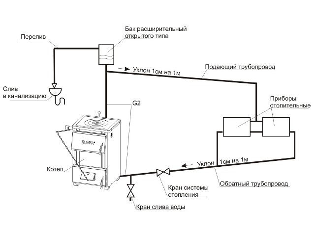
Conditions for the formation of scale. Steam boiler blowdown
Conditions for the formation of scale. Steam boiler blowdown
When water evaporates, the concentration of salts in it continuously increases. If salts are not removed from the boiler, then at a certain concentration in water, they fall out of the solution and are deposited on the heating surface in the form of scale. When heated to 80 - 100 ° C, Ca and Mg bicarbonates dissolved in water (Ca (HCO3) g, Mg (HC03) 2) decompose, forming sludge, and precipitate at the lower points of the boiler (lower drums and collectors).
Scale is concentrated on the most heat-stressed surfaces of screen and boiler pipes and boiler drums. Scale conducts heat 40 times (from 20 to 100 in different boilers) worse than iron, therefore, when working with scale, fuel consumption increases and the reliability of the boiler heating surfaces decreases. (Soot conducts heat 400 times worse).
Dependence of excessive fuel consumption on scale thickness
Scale thickness, mm
Average value of excessive fuel consumption, %
Due to the low thermal conductivity of the scale, the metal of the boiler and screen pipes is poorly cooled and subjected to severe overheating, as a result of which its strength decreases. This leads to the appearance of bulges, cracks, rupture of pipes and even to the explosion of drums, boilers. On modern water-tube boilers, the operation of the boiler under the condition of scale formation is unacceptable. Boilers must operate in a scale-free mode. Blowdown of steam boilers To maintain the permissible salinity of the boiler water, the boilers are blown. Blowdown is the removal of foreign impurities (salts, sludge, alkalis, suspended solids, etc.) from the boiler together with the boiler water while simultaneously replacing the blown water with feed water. Blowing can be periodic and continuous. Periodic blowing is carried out at certain intervals and is intended to remove sludge from the lower points of the boiler: the drum, screen collectors, etc. It is performed for a short time, but with a large discharge of boiler water, which entrains and carries the sludge out. Purging is carried out into an expander designed to cool water before discharging it into the sewer. Continuous purging provides a constant removal of dissolved salts of constant hardness to maintain their permissible concentration. Continuous blowing is usually from the top drum and is controlled by a needle valve. The water is diverted to the expander (separator), where the steam is separated from the water. Both steam and water are used to heat raw or chemically treated water (their heat is used). The timing and duration of blowdowns are set by the instruction or the head of the boiler room (according to the instructions of the laboratory).
If you are not a specialist and there is no time to deal with website development, you can always contact a qualified company that will be ready to create a website for you.
Whatever mood you and your friends have, you can always buy a gift for any holidays
In our store you can always buy diapers and make your child happy
What is pyrolysis combustion anyway?
Heating with wood is not very convenient, because under normal conditions, wood burns out very quickly, and a significant part of the heat is not used. You have to constantly load fuel into the boiler or furnace. Pyrolysis involves creating conditions under which the fuel burns much more slowly, while giving off a noticeably greater amount of heat. This effect is achieved when the wood burns out at a low oxygen content, that is, very slowly. As a result, ash, coke and combustible gas are formed.
This gas is mixed with air in the pyrolysis plant and also burns at very high temperatures, releasing a significant amount of thermal energy. Thus, the principle of operation of the pyrolysis boiler includes two stages of combustion:
- first, with a limited supply of oxygen, wood burns out, releasing combustible gas;
- then the combustion of the air-gas mixture occurs.
A similar principle of two-stage combustion is used in various home-made installations, for example, in a slow-burning wood-burning stove and even in solid fuel generators that allow the use of wood as fuel for cars. However, the operation of the pyrolysis boiler should be properly adjusted so as not to damage the heating system at home.
The high price of industrial boilers is fully justified. Firstly, because high-quality materials are used in their creation that can withstand high combustion temperatures (heat-resistant iron, 8 mm alloy steel, fireclay, etc.). Secondly, because of the complex automatic control system, which ensures the high efficiency of the equipment.
To ensure the maximum combustion effect, the heating temperature of the firewood and their initial humidity are taken into account, since the process of water evaporation significantly affects the amount of energy released. In order to control the combustion process, it is necessary to carefully control the amount of air supplied to the installation. Air is supplied by a fan, which requires constant access to electricity. The presence of a fan turns the pyrolysis boiler into an electrically dependent installation. In the event of a power outage, it is recommended to use a UPS or similar device.
Installation progress of solid fuel boiler
Despite the progress in the field of electrification and gasification of the country, there are still many places where these communications are practically absent. But even where they are, many people prefer to arrange independent heating and hot water supply in their homes.
To do this, a solid fuel boiler is installed, which allows you to get heat and hot water in a private house, cottage or cottage at much lower operating costs and financial investments. The choice of this type of equipment is quite large, but all of it has fairly clear connection schemes for various types of heating.
Diagrams and drawings of the boiler blowdown
Boiler purge scheme
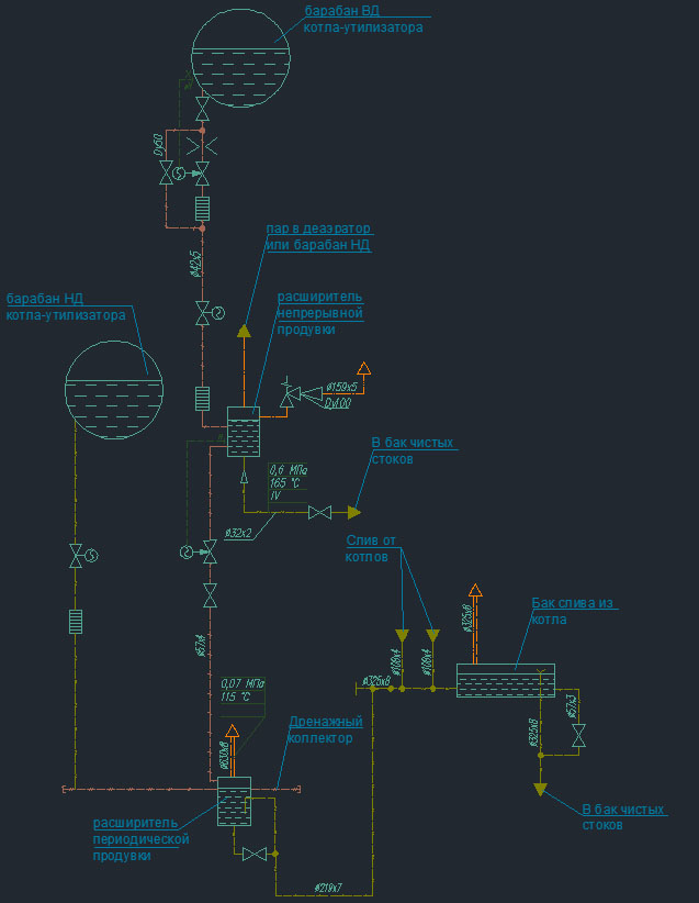
boiler purge scheme
This is part of a real deployed scheme of a 450 MW combined cycle plant. The diagram shows how continuous and intermittent purging is carried out.
The continuous blowdown from the high pressure drum enters the continuous blowdown separator/expander. The following is installed on the line along the flow of the medium: a shut-off manual valve, a flow meter, an electrified regulator, a set of throttle washers, electrified fittings and a set of throttle washers.
At the end of the article, an example of calculating a continuous blowdown expander is given.
RNP is equipped with a safety valve.
In this scheme, saturated steam from the continuous blowdown separator is sent to the low pressure drum. A shut-off manual valve and a check valve are installed on the steam pipeline. Drainage from the RNP will be sent to a clean waste tank.
The blowdown from the RNP is sent to the intermittent blowdown expander, an electric control valve and manual shut-off valves are installed on the line. Further, the drainage from the RPP is discharged into the drain tank from the boilers.
Drawing of the steam pipeline from the continuous blowdown separator to the deaerator

steam from RNP to deaerator
The design assembly drawing shows the layout of the low-pressure steam pipeline from the continuous blowdown expander to the atmospheric deaerator.Two fittings are installed on the steam pipeline, one is a shut-off valve (position 2) and the other is a check valve (position 1) so that steam cannot go back to the expander.
Exhaust drawing from RNP safety valve

purge from the RNP safety valve
Another drawing shows the exhaust piping from the RNP relief valve. The pipeline from the safety valve is directed to the edge of the main building and in the alignment of the columns is led to the roof, to a height of more than 2 meters, to ensure the safety of the station personnel. A water seal is provided on the exhaust pipeline to remove drainage into the drainage collector. From operating experience, it is recommended to make the diameter of the water seal pipe larger than that of conventional drainage in order to prevent its clogging, since leaves and other dirt can enter the exhaust pipeline from the atmosphere.
Drawing of flash steam from the intermittent blowdown expander

flash from blowdown expander
The drawing shows flash from a blowdown expander. It is also displayed outside the building but from the side. Vapour, unlike exhaust, is permanent. To cool the steam, a special device for injecting cold water into the pipeline is provided.
How to assemble such a unit yourself
To make such a complex device, you need a fairly wide range of tools and materials. Here is a sample list of them:
- electric drill;
- welding machine (DC model recommended);
- several packages of electrodes;
- Bulgarian;
- grinding wheel 125 mm;
- cutting wheel 230 mm;
- metal sheets 4 mm;
- a set of pipes of various diameters;
- set of professional pipes 2 mm;
- several strips of steel of different widths and thicknesses;
- fan;
- temperature sensor.
The recommended thickness of steel, which is used in the independent manufacture of a pyrolysis boiler, is 4 mm. However, in order to save money, 3 mm steel can be used for the body of the device.
 The body of the pyrolysis boiler should be made of sufficiently strong steel that can withstand high temperatures. The thickness of the metal must be at least 3 mm
A careful study of the diagrams, drawings and devices of the pyrolysis boiler allows us to proceed to its actual manufacture. With the help of a grinder, the necessary elements are cut out. Then the welding machine is used. The assembly of the pyrolysis boiler is presented in great detail in the following video:
In addition, a number of recommendations should be followed:
- The fuel inlet for home-made models is usually placed slightly higher than for conventional solid fuel boilers.
- It is imperative to install a limiter that will allow you to control the amount of air entering the fuel chamber, as well as to place firewood or briquettes in a timely manner.
- For the manufacture of the limiter, you can use a pipe with a diameter of about 70 mm, a little longer than the body of the device.
- A steel disk should be welded to the lower part of the limiter, forming a gap of about 40 mm with the pipe walls.
- To install the limiter in the boiler cover, make an appropriate hole.
- The loading hole for firewood should be made rectangular. Close this hole with a door, with a special steel lining that provides a secure fit.
- Below you need to make a hole to remove the ash.
- The pipe through which the coolant moves inside the boiler must be made with a bend in order to maximize heat transfer.
- The amount of heat carrier entering the boiler can be regulated using a valve installed outside.
If after the first start-up of the boiler there is no carbon monoxide in the combustion products, then the design is made accurately and functions correctly. In the future, you should regularly monitor the condition of the welds of the boiler and promptly clean it from accumulated ash and soot.
Please note that the use of a pyrolysis boiler not with traditional water heating, but with air heating systems is considered a very successful combination. Air in this case is transmitted through pipes, and returns to the system through the floor
Such a system will not freeze during a sharp cold snap; in the event of the departure of the owners of the house, there is no need to drain the coolant.
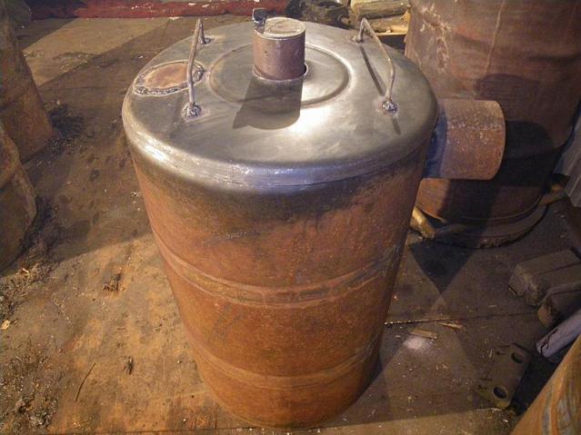
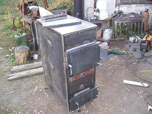
Pyrolysis boiler from a barrel
We need a 200 liter metal barrel. You can take a finished one, or you can bend and weld a sheet of steel 3-4 mm thick. We cut off its upper end and make a cover out of it, welding a strip of metal around the circumference. We drill a hole in the center for the air pipe. On the side in the upper part of the barrel, we drill a hole for the chimney and weld the chimney pipe into it.
Next we make the piston. It is a circle, slightly smaller in diameter than the lid of the barrel, so that it can fit into it. A hole is drilled in the center and an air pipe is welded to it, through which oxygen will flow into the furnace.
 Pyrolysis boiler from a barrel
In the upper part we make a damper that will regulate the amount of air entering inside. To do this, we drill a through hole, insert a tight pin into it and weld a small plate inside it. By rotating it, we change the area of the hole.
From below, the steel sheet must be weighted so that during combustion, the piston, under its own weight, lowers and grinds the burnt fuel
It is important that all welds are sealed. If this is not the case, the boiler will not be able to work efficiently enough.
Using such a homemade boiler is simple. Fuel is poured to the bottom and set on fire. When it flares up enough, a piston is installed on top and the lid is closed. As it burns, the piston will gradually lower.
A smoldering process will take place under it, and the emitted gases will burn on top of it. This design is also called a pyrolysis head and can run on wood or related fuels from wood waste.
Analysis of the scheme, drawings and calculations
To better understand the principle of operation of the device, it is recommended to study the scheme of the pyrolysis boiler.
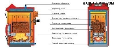 Before starting work, it is recommended to carefully study the scheme of the pyrolysis boiler in order to understand the principles of its operation and avoid mistakes.
It reflects the position of such necessary elements as:
- air hole;
- the combustion chamber;
- smoke channels;
- pipes for supply and drainage of water;
- regulators;
- fan installation location, etc.
Since the pyrolysis boiler is a rather complicated device, it is recommended to adhere to the drawing when manufacturing it. One of the most common device models that is suitable for self-production is presented below:
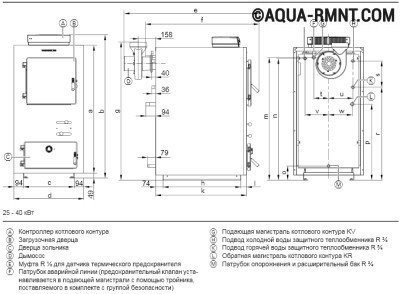 This drawing shows in detail the design of the pyrolysis boiler, which you can do yourself. It is recommended to strictly observe all dimensions specified by the developer.
Usually, a 40 kW boiler is used for a private house. If this indicator needs to be increased or decreased, it is recommended to change the device parameters accordingly. The required data is presented in the table:
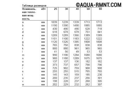 To make a pyrolysis boiler of suitable power with your own hands, you need to make elements of the appropriate size. The right size ratio guarantees a successful result
A 25-30 kW boiler can be the best choice for a small house. Making a small unit will save both time and money.
Step by step installation
In any instruction attached to the boiler, there are recommendations for installing equipment. Installation of a solid fuel boiler must be carried out clearly according to the instructions and technical rules of the manufacturer.
It is necessary to follow the sequence of actions.
First you need to arrange a solid base of non-combustible material under the bottom 20 cm wider than the base of the unit, it is best to pour a concrete base. After that, you need to install the boiler on a solid base, taking into account all distances, adjust the horizontal and vertical position of the device.
Connecting pipes and safety elements
Adhering to the connection diagram, make a tie-in of the safety group in a complete set for this type of boiler, which is placed before the stopcocks.
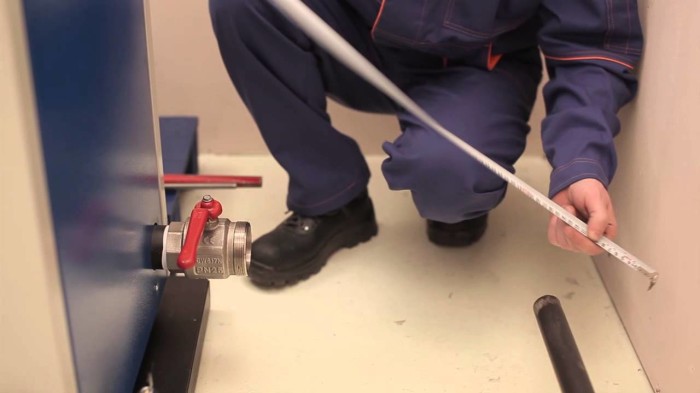
After that, the heating pipes should be connected, it is desirable to connect through the shut-off valves, while the joints are carefully sealed with flax or plumbing tape.
Next, you need to assemble the chimney, in which good traction depends on the correctly selected cross-sectional area and the height of the pipe, all joints must be coated with a heat-resistant sealant.
Final stage
At the next stage, it is already possible to fill the heating system with water at a higher pressure and check for leaks. After that, it is necessary to check the location of the grates, dampers, plugs, fireclay stones. At the end of the installation, you need to relieve the water pressure to the working one, install dampers in the chimney and firebox, load firewood.
Now you can fire up the boiler, when the design temperature is reached, turn on the thermostat to the selected level of heat supply for comfortable heating of the room and do not forget to put firewood in the furnace in time.
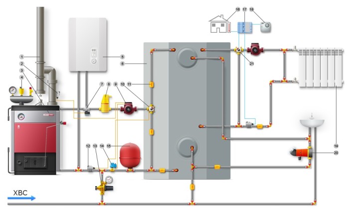
We connect a solid fuel boiler to the heating system problems and their solution
Unlike electric and gas heating units, solid fuel boilers are almost never equipped with circulation pumps, a safety group, adjustment and control devices. Everyone solves these issues on their own, choosing a heating device piping scheme in accordance with the type and features of the heating system. Not only the efficiency and productivity of heating, but also its reliable, trouble-free operation depend on how correctly the installation of the heat generator is carried out.
That is why it is important to include components and devices in the circuit that will ensure the durability of the heating unit and its protection in case of emergency situations.
In addition, when installing a solid fuel boiler, you should not refuse equipment that creates additional convenience and comfort. With the help of a heat accumulator, it is possible to solve the problem of temperature differences during the reboot of the boiler, and an indirect heating boiler will provide the house with hot water. Thinking about connecting a solid fuel heating unit in accordance with all the rules? We will help you with this!
Boiler according to the Belyaev scheme
We will need the following materials:
- About 10 square meters of metal sheet 4-5mm thick.
- 8 meters of steel pipe, 57 mm in diameter with a wall thickness of 3.5 mm.
- One meter of pipe with a diameter of 159 mm and 32 mm.
- 15 pieces of fireclay bricks.
- Blower fan. Blower fan on a pyrolysis boiler
- Steel strips, 20, 30 and 80 mm wide.
Of the main tools, you will need a grinder, a drill and a welding machine.
Step-by-step instructions for assembling a pyrolyzer:
- There are two combustion chambers. A firebox in which wood will burn and gas, where the emitted gases burn.
- The rear wall and air vents from a channel or professional pipe with drilled holes are welded to them.
- A hole is made in the furnace and a pipe is welded in through which oxygen will enter.
- The next is the heat exchanger. To do this, we take two metal plates and drill symmetrical holes in them for a pipe with a cross section of 57 mm.
The pipe is cut into pieces of the same length, and they are welded into blanks. Then it is welded to the boiler.
Before making and welding the front wall to the combustion chambers, two holes are made in it. They will be designed for inlet and outlet air pipes. Scheme of the pyrolysis boiler
A burr and a cover are welded in front of the damper. It is important to clean all welding seams with a grinder.
From above, we sheathe the entire structure with a sheet 4 mm wide with corners. The upper part is additionally insulated. After that, we check the box for tightness. You can do this with water. If there is no tightness, the efficiency of the boiler will decrease significantly.
The doors for the combustion chambers are made of cast iron plates. Hinges are welded and they are installed. Latches are placed on top.
We lay out the lower chamber with bricks. before cutting them to the required size. Since they will not be visible, it is not necessary to buy new ones. Can be found for free near any destroyed building.
A blower fan is installed at the outlet of the air pipe.
Also, such a design can be made from the KST of the boiler, using it as a body.
Connection methods
A fairly common way is to connect the water heater to the system in a closed circuit.
The body of solid fuel boilers is not equipped with an expansion tank, a circulation pump and other elements that ensure the safety of its operation. Therefore, all this equipment must be included in the boiler piping from the side of the heat circuit.
When inserting the device into the system, it must be remembered that the expansion of the coolant in these units often takes on an uncontrolled character.
Therefore, it is better to install a solid fuel boiler in an open circuit, when excess water during overheating simply pours out through the tube of the expansion tank. Otherwise, the increased pressure in the pipes can lead to their rupture.
With mixing unit
The second connection method involves the presence of a mixing unit. According to the instructions, the coolant at the entrance to the boiler must have a heating temperature of at least 60 degrees in order to avoid large thermal fluctuations. Violation of this paragraph will reduce the life of the unit and lead to excessive pollution.
To avoid such surprises, a mixing unit must be connected to the heater piping, which will, if necessary, supply hot water from the pipeline and mix it with cold water from the system.
The third method is a scheme for connecting a buffer tank to the boiler piping to control the water temperature. When the coolant has a high temperature, the buffer absorbs excess heat, and after the boiler cools down, it releases it to the heating system.
Thus, the thermal circuit is protected from sudden changes, which allows you to maintain a constant temperature in the house.
How to make a pyrolysis boiler with your own hands drawings and diagrams
First of all, in order to design a pyrolysis boiler with your own hands, a suitable scheme and drawing are selected.
Consider three main manufacturing methods from various materials:
- From a barrel or a steel sheet in the form of a cylinder.
- From strong steel in a cubic form, using the Belyaev scheme,
- From a brick in the form of an oven. Before choosing the type of boiler you will build, review all drawings and diagrams, as well as assembly instructions.
Each type of homemade long-burning equipment has its own advantages and disadvantages. The barrel will make a compact design for the garage, and the brick oven will be able to heat the whole house, significantly saving fuel.
Continuous blowdown of steam boilers
Continue reading “Conflict of Interest. How not to harm the system by improving the operation of individual installations”, today we will talk about how the measures aimed at optimizing the operation of boiler equipment affect the overall efficiency of the steam system, namely the automation of the continuous blowdown of the steam boiler and the use of continuous blowdown heat.
Let's try to figure out why a continuous blowdown of a steam boiler is necessary.
When the water in the steam boiler evaporates, any impurities contained in the feed water are not carried away with the steam, but remain in the boiler water.As a result, the concentration of dissolved solids in the boiler water increases more and more over time. The salt content in the boiler increases, which in turn leads to foaming on the surface of the boiler. Foam from the surface is carried away from the boiler into the steam pipeline. Foaming is also the reason for turning off the boiler on the "Level in the drum" protection.
To eliminate these problems, boiler manufacturers determine the maximum salt content in the boiler. Based on the value of the maximum salt content in the boiler and the existing salinity in the feed water, you can find the minimum value of the continuous blowdown of the boiler:
Dnp \u003d Dk * Spv / (Smax - Spv)
Dnp - continuous purge flow rate; Dk is the feed water consumption for the boiler (t/h); Spv is the salinity of the feed water (µg/kg); Сmax - maximum salt content in the boiler (µg/kg)
Heat loss with continuous blowdown will be:
Qpot \u003d Dnps * inp - Dnpb * isb
Qpot - heat lost with continuous purge (kcal/h); Dnps - existing flow rate of continuous blowing (t/h); Dnpb - continuous blowdown consumption, after installation of a continuous blowdown heat recovery unit (t/h); inp is the enthalpy of continuous blowdown at pressure in the boiler (kcal/kg); isb is the continuous blowdown enthalpy after installation of the continuous blowdown heat recovery unit (kcal/kg).
In the absence of automation for continuous blowdown of the boiler, the existing flow rate of continuous blowdown significantly exceeds the minimum required flow rate of continuous blowdown. This is due to the fact that analyzes of the salt content in the boilers are carried out once a day and in order to prevent the salt content in the boilers from exceeding the limit, it is necessary to maintain the salt content in the boiler at the minimum allowable level.
Exceeding the discharge of the continuous blowdown of the boiler leads to thermal energy losses amounting to 1–3% of the thermal energy of the produced steam.
In the presence of automatic control of continuous blowdown, it is possible to maintain the salinity in the boiler by 2-3% below the maximum allowable salt content, which leads to a decrease in the consumption of continuous blowdown.
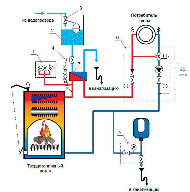
When automating continuous blowdown, my colleagues and I propose to use the heat of continuous blowdown to produce flash steam and heat any existing flow: - make-up water to the deaerator, (Fig. 1) - feed water before the steam boiler. (Fig. 2)
Let us analyze the impact of the listed energy efficiency measures in relation to their impact on other parameters of the plant operation: