The actual question is what diameter of the pipeline to apply
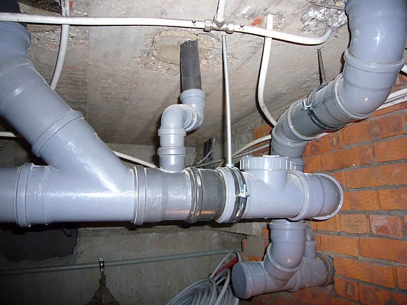
The schematic diagram of the steam condensate path looks like this. The boiler plant is operating, which produces steam of a certain parameter in a certain amount. Then the main steam valve opens and steam enters the steam condensate system, moving towards consumers. And then the actual question arises, what diameter of the pipeline should be used?
If you take a pipe of too large a diameter, then this threatens:
- Increasing the cost of installation
- Large heat loss to the environment
- A large amount of condensate, and therefore a large number of condensate pockets, steam traps, valves, etc.
If you take a pipe of too small diameter, then this threatens:
- Pressure loss below design
- Increased steam speed, noise in the steam line
- Erosive wear, more frequent equipment replacement due to water hammer
Calculation of the steam pipeline diameter
There are two methods for choosing the diameter of the steam line: the first is the pressure drop method, and the second is the simpler one that most of us use - the velocity method.
In order for you not to waste your time searching for a table for calculating the speed method, we have posted this information on this page for your convenience. Published recommendations are taken from the catalog of the manufacturer of industrial pipeline valves ADL.
Capacity of the sewer pipe
The capacity of the sewer pipe is an important parameter that depends on the type of pipeline (pressure or non-pressure). The calculation formula is based on the laws of hydraulics. In addition to the laborious calculation, tables are used to determine the capacity of the sewer.
Hydraulic Calculation Formula
For the hydraulic calculation of sewerage, it is required to determine the unknowns:
- pipeline diameter Du;
- average flow velocity v;
- hydraulic slope l;
- degree of filling h / Du (in calculations, they are repelled from the hydraulic radius, which is associated with this value).
| DN, mm | h/DN | Self-cleaning speed, m/s |
| 150-250 | 0,6 | 0,7 |
| 300-400 | 0,7 | 0,8 |
| 450-500 | 0,75 | 0,9 |
| 600-800 | 0,75 | 0,1 |
| 900+ | 0,8 | 1,15 |
In addition, there is a normalized value for the minimum slope for pipes with a small diameter: 150 mm
(i=0.008) and 200 (i=0.007) mm.
The formula for the volumetric flow rate of a liquid looks like this:
q=a·v,
where a is the free area of the flow,
v is the flow velocity, m/s.
The speed is calculated by the formula:
v=C√R*i,
where R is the hydraulic radius;
C is the wetting coefficient;
i - slope.
From this we can derive the formula for the hydraulic slope:
i=v2/C2*R
According to it, this parameter is determined if calculation is necessary.
С=(1/n)*R1/6,
where n is the roughness factor, ranging from 0.012 to 0.015 depending on the pipe material.
The hydraulic radius is considered equal to the usual radius, but only when the pipe is completely filled. In other cases, use the formula:
R=A/P
where A is the area of the transverse fluid flow,
P is the wetted perimeter, or the transverse length of the inner surface of the pipe that touches the liquid.

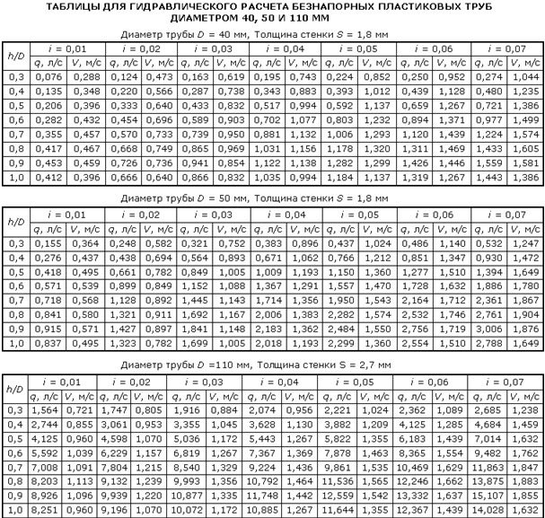
Capacity tables for non-pressure sewer pipes
The table takes into account all the parameters used to perform the hydraulic calculation. The data is selected according to the value of the pipe diameter and substituted into the formula. Here, the volumetric flow rate q of the liquid passing through the pipe section has already been calculated, which can be taken as the throughput of the pipeline.
In addition, there are more detailed Lukin tables containing ready-made throughput values for pipes of different diameters from 50 to 2000 mm.
Capacity tables for pressurized sewer systems
In the capacity tables for sewer pressure pipes, the values depend on the maximum degree of filling and the estimated average flow rate of the waste water.
| Diameter, mm | Filling | Acceptable (optimal slope) | The speed of movement of waste water in the pipe, m / s | Consumption, l / s |
| 100 | 0,6 | 0,02 | 0,94 | 4,6 |
| 125 | 0,6 | 0,016 | 0,97 | 7,5 |
| 150 | 0,6 | 0,013 | 1,00 | 11,1 |
| 200 | 0,6 | 0,01 | 1,05 | 20,7 |
| 250 | 0,6 | 0,008 | 1,09 | 33,6 |
| 300 | 0,7 | 0,0067 | 1,18 | 62,1 |
| 350 | 0,7 | 0,0057 | 1,21 | 86,7 |
| 400 | 0,7 | 0,0050 | 1,23 | 115,9 |
| 450 | 0,7 | 0,0044 | 1,26 | 149,4 |
| 500 | 0,7 | 0,0040 | 1,28 | 187,9 |
| 600 | 0,7 | 0,0033 | 1,32 | 278,6 |
| 800 | 0,7 | 0,0025 | 1,38 | 520,0 |
| 1000 | 0,7 | 0,0020 | 1,43 | 842,0 |
| 1200 | 0,7 | 0,00176 | 1,48 | 1250,0 |
Correspondence of the diameter of the pipes to the volume of the carrier
Water is used as the heat carrier in most heating systems. It is heated by a central boiler. The energy source is gas, electricity, flammable liquids or solid fuels. This node is the heart of the heating system. The heating unit, lines, constipation and heat-releasing radiators form a complex scheme in which each element must be scrupulously verified. Forecasting energy costs and the required power of the boiler, calculating the heating pipe, choosing the carrier and type of fuel optimize costs during construction and operation. Initial foresight will insure against early repairs and the need to refine the heating main that has already been put into operation.
 The device of an autonomous heating system
The calculation of pipes for heating a private house can be ordered by professionals, trusting in experience. Plumbing "calculators" help to display indicators on their own: programs that calculate pipes for heating are offered on the websites of manufacturers and stores. The calculators contain average indicators of typical radiators and pipes: the owner needs to specify the footage, ceiling height and type of building, so that the system itself calculates registers from smooth pipes for heating or boiler capacity. Lack of calculators in pre-configuration for the needs of a particular service. It is unlikely that the owners of the portal will place a program that recommends the products of competitors, even if the calculation of the section of the heating pipe based on real characteristics provided for this.
Nuances when choosing the diameter of the pipes of the heating system
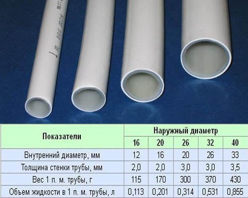
Description of pipe diameters
When choosing the diameter of heating pipes, it is customary to focus on the following characteristics:
- inner diameter - the main parameter that determines the size of products;
- outer diameter - depending on this indicator, pipes are classified:
- small diameter - from 5 to 102 mm;
- medium - from 102 to 406 mm;
- large - more than 406 mm.
- conditional diameter - the value of the diameter, rounded to whole numbers and expressed in inches (for example, 1 ″, 2 ″, etc.), sometimes in fractions of an inch (for example, 3/4 ″).
Large or small diameter
If you are interested in how to calculate the diameter of a heating pipe, pay attention to our recommendations. The outer and inner sections of the pipe will differ by an amount equal to the wall thickness of this pipe
Moreover, the thickness varies depending on the material of manufacture of products.
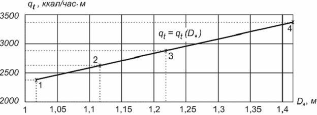
Graph of dependence of heat flow on the outer diameter of the heating pipe
Professionals believe that when installing a forced heating system, the diameter of the pipes should be as small as possible. And this is no accident:
- the smaller the diameter of the plastic pipes for the heating system, the smaller the amount of coolant that needs to be heated (saving time for heating and money for energy carriers);
- with a decrease in the cross section of pipes, the speed of movement of water in the system slows down;
- small diameter pipes are easier to install;
- pipelines from pipes of small diameters are more cost-effective.
However, this does not mean that, contrary to the design of the heating system, it is necessary to purchase pipes with a diameter smaller than that obtained in the calculation. If the pipes are too small, this will make the system noisy and inefficient.
There are specific values that describe the ideal speed of the coolant in the heating system - this is an interval from 0.3 to 0.7 m / s. We advise you to look up to them.
Practical assessment of the required size of the pipeline pipe, steam pipeline according to the flow rate and pressure of saturated steam in the range of 0.4-14 bar instrument pressure and DN15-300 mm. Table.
- In general, a calm (quite sufficient) speed for saturated steam is 25 m/s. The maximum allowable steam speeds from the project dpva.ru
- The table is practically suitable for all pipe schedules, but not all pipe schedules are suitable for steam. In general, steam is a rather unpleasant working environment, but ordinary carbon steel pipes are used in most cases, although stainless steel is also often used. Overview of steel designations from the dpva.ru project Overview of steel pipe standards from the dpva.ru project.
| Saturated steam consumption (kg/h Other units of measurement from the dpva.ru project) | |||||||||||||||
| Instrument pressure (bar) | Steam speed (m/s) | Conditional (nominal) pipe diameter mm | |||||||||||||
| 15 | 20 | 25 | 32 | 40 | 50 | 65 | 80 | 100 | 125 | 150 | 200 | 250 | 300 | ||
| 0.4 | 15 | 7 | 14 | 24 | 37 | 52 | 99 | 145 | 213 | 394 | 648 | 917 | 1606 | 2590 | 3680 |
| 25 | 10 | 25 | 40 | 62 | 92 | 162 | 265 | 384 | 675 | 972 | 1457 | 2806 | 4101 | 5936 | |
| 40 | 17 | 35 | 64 | 102 | 142 | 265 | 403 | 576 | 1037 | 1670 | 2303 | 4318 | 6909 | 9500 | |
| 0.7 | 15 | 7 | 16 | 25 | 40 | 59 | 109 | 166 | 250 | 431 | 680 | 1006 | 1708 | 2791 | 3852 |
| 25 | 12 | 25 | 45 | 72 | 100 | 182 | 287 | 430 | 716 | 1145 | 1575 | 2816 | 4629 | 6204 | |
| 40 | 18 | 37 | 68 | 106 | 167 | 298 | 428 | 630 | 1108 | 1715 | 2417 | 4532 | 7251 | 10323 | |
| 1 | 15 | 8 | 17 | 29 | 43 | 65 | 112 | 182 | 260 | 470 | 694 | 1020 | 1864 | 2814 | 4045 |
| 25 | 12 | 26 | 48 | 72 | 100 | 193 | 300 | 445 | 730 | 1160 | 1660 | 3099 | 4869 | 6751 | |
| 40 | 19 | 39 | 71 | 112 | 172 | 311 | 465 | 640 | 1150 | 1800 | 2500 | 4815 | 7333 | 10370 | |
| 2 | 15 | 12 | 25 | 45 | 70 | 100 | 182 | 280 | 410 | 715 | 1125 | 1580 | 2814 | 4545 | 6277 |
| 25 | 19 | 43 | 70 | 112 | 162 | 195 | 428 | 656 | 1215 | 1755 | 2520 | 4815 | 7425 | 10575 | |
| 40 | 30 | 64 | 115 | 178 | 275 | 475 | 745 | 1010 | 1895 | 2925 | 4175 | 7678 | 11997 | 16796 | |
| 3 | 15 | 16 | 37 | 60 | 93 | 127 | 245 | 385 | 535 | 925 | 1505 | 2040 | 3983 | 6217 | 8743 |
| 25 | 26 | 56 | 100 | 152 | 225 | 425 | 632 | 910 | 1580 | 2480 | 3440 | 6779 | 10269 | 14316 | |
| 40 | 41 | 87 | 157 | 250 | 357 | 595 | 1025 | 1460 | 2540 | 4050 | 5940 | 10479 | 16470 | 22950 | |
| 4 | 15 | 19 | 42 | 70 | 108 | 156 | 281 | 432 | 635 | 1166 | 1685 | 2460 | 4618 | 7121 | 10358 |
| 25 | 30 | 63 | 115 | 180 | 270 | 450 | 742 | 1080 | 1980 | 2925 | 4225 | 7866 | 12225 | 17304 | |
| 40 | 49 | 116 | 197 | 295 | 456 | 796 | 1247 | 1825 | 3120 | 4940 | 7050 | 12661 | 1963 | 27816 | |
| Saturated steam consumption (kg/h Other units of measurement from the dpva.ru project) | |||||||||||||||
| Instrument pressure (bar) | Steam speed (m/s) | Conditional (nominal) pipe diameter mm | |||||||||||||
| 15 | 20 | 25 | 32 | 40 | 50 | 65 | 80 | 100 | 125 | 150 | 200 | 250 | 300 | ||
| 5 | 15 | 22 | 49 | 87 | 128 | 187 | 352 | 526 | 770 | 1295 | 2105 | 2835 | 5548 | 8586 | 11947 |
| 25 | 36 | 81 | 135 | 211 | 308 | 548 | 885 | 1265 | 2110 | 3540 | 5150 | 8865 | 14268 | 20051 | |
| 40 | 59 | 131 | 225 | 338 | 495 | 855 | 1350 | 1890 | 3510 | 5400 | 7870 | 13761 | 23205 | 32244 | |
| 6 | 15 | 26 | 59 | 105 | 153 | 225 | 425 | 632 | 925 | 1555 | 2525 | 3400 | 6654 | 10297 | 14328 |
| 25 | 43 | 97 | 162 | 253 | 370 | 658 | 1065 | 1520 | 2530 | 4250 | 6175 | 10629 | 17108 | 24042 | |
| 40 | 71 | 157 | 270 | 405 | 595 | 1025 | 1620 | 2270 | 4210 | 6475 | 9445 | 16515 | 27849 | 38697 | |
| 7 | 15 | 29 | 63 | 110 | 165 | 260 | 445 | 705 | 952 | 1815 | 2765 | 3990 | 7390 | 12015 | 16096 |
| 25 | 49 | 114 | 190 | 288 | 450 | 785 | 1205 | 1750 | 3025 | 4815 | 6900 | 12288 | 19377 | 27080 | |
| 40 | 76 | 177 | 303 | 455 | 690 | 1210 | 1865 | 2520 | 4585 | 7560 | 10880 | 19141 | 30978 | 43470 | |
| 8 | 15 | 32 | 70 | 126 | 190 | 285 | 475 | 800 | 1125 | 1990 | 3025 | 4540 | 8042 | 12625 | 17728 |
| 25 | 54 | 122 | 205 | 320 | 465 | 810 | 1260 | 1870 | 3240 | 5220 | 7120 | 13140 | 21600 | 33210 | |
| 40 | 84 | 192 | 327 | 510 | 730 | 1370 | 2065 | 3120 | 5135 | 8395 | 12470 | 21247 | 33669 | 46858 | |
| 10 | 15 | 41 | 95 | 155 | 250 | 372 | 626 | 1012 | 1465 | 2495 | 3995 | 5860 | 9994 | 16172 | 22713 |
| 25 | 66 | 145 | 257 | 405 | 562 | 990 | 1530 | 2205 | 3825 | 6295 | 8995 | 15966 | 25860 | 35890 | |
| 40 | 104 | 216 | 408 | 615 | 910 | 1635 | 2545 | 3600 | 6230 | 9880 | 14390 | 26621 | 41011 | 57560 | |
| 14 | 15 | 50 | 121 | 205 | 310 | 465 | 810 | 1270 | 1870 | 3220 | 5215 | 7390 | 12921 | 20538 | 29016 |
| 25 | 85 | 195 | 331 | 520 | 740 | 1375 | 2080 | 3120 | 5200 | 8500 | 12560 | 21720 | 34139 | 47128 | |
| 40 | 126 | 305 | 555 | 825 | 1210 | 2195 | 3425 | 4735 | 8510 | 13050 | 18630 | 35548 | 54883 | 76534 |
Selection of steam line diameter
December 15, 2018
The actual question is, what diameter of the pipeline should be used?
The schematic diagram of the steam condensate path looks like this. The boiler plant is operating, which produces steam of a certain parameter in a certain amount. Then the main steam valve opens and steam enters the steam condensate system, moving towards consumers. And then the actual question arises, what diameter of the pipeline should be used?
If you take a pipe of too large a diameter, then this threatens:
- Increasing the cost of installation
- Large heat loss to the environment
- A large amount of condensate, and therefore a large number of condensate pockets, steam traps, valves, etc.
If you take a pipe of too small diameter, then this threatens:
- Pressure loss below design
- Increased steam speed, noise in the steam line
- Erosive wear, more frequent equipment replacement due to water hammer
Calculation of the steam pipeline diameter
There are two methods for choosing the diameter of the steam line: the first is the pressure drop method, and the second is the simpler one that most of us use - the velocity method.
In order for you not to waste your time searching for a table for calculating the speed method, we have posted this information on this page for your convenience. Published recommendations are taken from the catalog of the manufacturer of industrial pipeline valves ADL.
Recommendations for installing drainage pockets
The starting loads on the steam pipeline are very high, since hot steam enters the cold, unheated pipeline and the steam begins to condense actively. According to SNiP 2.04.07-86 * Clause 7.26, it is required to make drainage pockets on straight sections of steam pipelines every 400-500 m and every 200-300 m with a counter slope, drainage of steam pipelines should be provided.
Different manufacturers of pipe fittings give their recommendations regarding the installation interval of steam traps. The Russian manufacturer ADL, based on its many years of experience, recommends the production of drainage pockets with the installation of Stimax steam traps every 30-50m with long pipeline lines. For short lines, the ADL recommendations do not differ from SNiP 2.04.07-86.
Why does condensate need to be removed from the steam line?
When steam is supplied, it develops very high speeds and drives the condensate film forming in the lower part of the pipe through the steam pipeline at a speed of 60 m / s and higher, forming comb-shaped condensate waves that can block the entire pipe section. Steam drives all this condensate, crashing into all obstacles in its path: fittings, filters, control valves, valves. Of course, for the pipeline itself, not to mention the equipment, it will be a strong water hammer.
What will be the conclusion?
- As often as possible, carry out drainage pockets with the installation of steam traps.
- Installation of filters in a horizontal plane, drain cap down to avoid a condensate pocket
- Properly produce concentric constrictions, avoiding condensate pockets
- Observe the slope for gravity drainage of condensate into drainage pockets
- Installation of valves instead of ball valves
- KR 11|12|15|20 rubber wedge gate valves
- Mesh filter series IS17
- Pump stations "Granflow" series UNV DPV
- Check valve series RD30
- Strainers series IS 15|16|40|17
- Bypass valve "Granreg" CAT32
- Circulation pump "Granpump" series R
- Check valves "Granlock" CVS25
- Steel ball valves BIVAL
- Mesh filter series IS30
- Steam equipment
- Circulation pumps "Granpump" series IPD
- Pressure regulator "Granreg" CAT41
- Safety valves Pregran KPP 096|095|097|496|095|495
- Bypass valve "Granreg" CAT82
- Steel ball valves BIVAL KSHT with reducer
- Pressure regulators "Granreg" CAT
- Pumping stations "Granflow" series UNV on pumps MHC and ZM
- Gate valve Granar series KR15 with fire certificate
- Check valve CVS16
- Bypass valve "Granreg" CAT871
- Dosing pump stations — DOZOFLOW
- Check valve CVS40
- Gate valve "Granar" series KR17 certification according to the FM Global form
- Granlock CVT16
- Circulation pumps "Granpump" series IP
- Pressure regulator “after itself “Granreg” CAT160|CAT80| CAT30| CAT41
- Monoblock stainless steel pumps MHC 50|65|80|100 series
- Gate valve "Granar" series KR16 certification according to the FM Global form
- Check valve series RD50
- Steam Traps Stimaks А11|A31|HB11|AC11
- Check valve series RD18
- Steel ball valves Bival KShG
- Butterfly valves Granval ZPVS|ZPVL|ZPTS|ZPSS
- Emergency pumping stations
- ← Saving water
- Influence of air and gases on heat transfer →