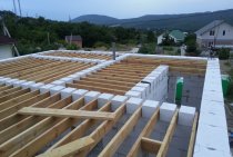
Layered floor structure
The process of laying the floor on the ground in a private house requires careful preparation. It is necessary to take into account the thickness of the concrete pavement and check whether it will restrict passages in doorways.
Pipes and cables running under the floor must also be insulated. Good preparation requires a subfloor. Its device should have the following layered structure:
- ground base;
- fine sand;
- crushed stone;
- waterproofing;
- rough concrete screed;
- vapor barrier;
- insulation;
- finishing reinforced screed;
- flooring.
- Some builders use other structuring, but this method is the most common.
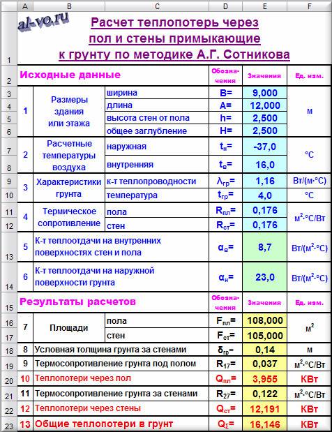
Calculation of heat losses in MS Excel through the floor and walls adjacent to the ground according to the method of Professor A.G. Sotnikov.
A very interesting technique for buildings buried in the ground is described in the article “Thermophysical calculation of heat losses in the underground part of buildings”. The article was published in 2010 in №8 of the ABOK magazine under the heading "Discussion Club".
Those who want to understand the meaning of what is written below should first study the above.
A.G. Sotnikov, relying mainly on the findings and experience of other predecessor scientists, is one of the few who, for almost 100 years, has tried to move the topic that worries many heat engineers. I am very impressed with his approach from the point of view of fundamental heat engineering. But the difficulty of correctly assessing the temperature of the soil and its thermal conductivity in the absence of appropriate survey work somewhat shifts the methodology of A.G. Sotnikov into a theoretical plane, moving away from practical calculations. Although at the same time, continuing to rely on the zonal method of V.D. Machinsky, everyone just blindly believes the results and, understanding the general physical meaning of their occurrence, cannot definitely be sure of the obtained numerical values.
What is the meaning of the methodology of Professor A.G. Sotnikov? He proposes to assume that all heat losses through the floor of a buried building “go” into the depths of the planet, and all heat losses through walls in contact with the ground are eventually transferred to the surface and “dissolve” in the ambient air.
This seems to be partly true (without mathematical justification) if there is sufficient deepening of the floor of the lower floor, but with a deepening of less than 1.5 ... 2.0 meters, there are doubts about the correctness of the postulates ...
Despite all the criticisms made in the previous paragraphs, it is the development of the algorithm of Professor A.G. Sotnikova seems to be very promising.
Let's calculate in Excel the heat loss through the floor and walls into the ground for the same building as in the previous example.
We write down the dimensions of the basement of the building and the estimated air temperatures in the block of initial data.
Next, you need to fill in the characteristics of the soil. As an example, let's take sandy soil and enter its thermal conductivity coefficient and temperature at a depth of 2.5 meters in January into the initial data. The temperature and thermal conductivity of the soil for your area can be found on the Internet.
The walls and floor will be made of reinforced concrete (λ
=1,7
W/(m °C)) 300mm thick (δ
=0,3
m) with thermal resistance R
=
δ
λ
=0,176
m 2 ° C / W.
And, finally, we add to the initial data the values of the heat transfer coefficients on the inner surfaces of the floor and walls and on the outer surface of the soil in contact with the outside air.
The program performs the calculation in Excel using the formulas below.
Floor area:
F pl
=
B
*A
Wall area:
F st
=2*
h
*(B
+
A
)
Conditional thickness of the soil layer behind the walls:
δ
conv.
=
f
(h
H
)
Thermal resistance of the soil under the floor:
R
17
=(1/(4*λ gr
)*(π
F
pl
) 0,5
Heat loss through the floor:
Q
pl
=
F
pl
*(t
v
—
t
gr
)/(R
17
+
R
pl
+1/α in
)
Thermal resistance of the soil behind the walls:
R
27
=
δ
conv.
/λ gr
Heat loss through walls:
Q
st
=
F
st
*(t
v
—
t
n
)/(1/α n
+
R
27
+
R
st
+1/α in
)
General heat loss to the ground:
Q
Σ
=
Q
pl
+
Q
st
2.Determination of heat loss through enclosing structures.
V
buildings, structures and premises
constant thermal conditions during
heating season to maintain
temperature at a given level
compare heat loss and heat gain
in the calculated steady state,
When is the greatest deficit possible?
warmth.
Heat loss
in rooms generally consist of
heat loss through the building envelope
Q ogp ,
heat consumption for heating the outdoor
infiltrating air entering
through opening doors and other openings
and gaps in fences.
Losses
heat through the fences are determined
according to the formula:
where:
A is the estimated area of the enclosing
structures or parts thereof, m 2 ;
K
- heat transfer coefficient of the enclosing
designs,
;
t int
— temperature of the internal air, 0 С;
text
— outside air temperature according to
parameter B, 0 C;
β
– additional heat losses determined
in fractions of the main heat losses.
Additional heat losses are taken according to;
n
-coefficient taking into account the dependence
outer surface position
enclosing structures in relation to
to the outside air, taken according to
Table 6 .
According to
the requirements of clause 6.3.4 were not taken into account in the project
heat loss through internal enclosing
structures, with temperature difference
in them 3 ° C
and more.
At
basement heat loss calculation
taken for the height of the above-ground part
distance from the finished floor of the first
floors to ground level. underground parts
exterior walls dealt with floors on
ground. Heat loss through floors on the ground
calculated by dividing the area
floors into 4 zones (I-III
zones 2m wide, IV
remaining area). Breakdown into
zone starts from ground level
outside wall and transferred to the floor.
Heat transfer resistance coefficients
each zone taken by .
Consumption
heat Q i
, W, for heating the infiltrating
air is determined by the formula:
Q i
= 0.28G i c(t in
– text)k
, (2.9),
where:
Gi —
consumption of infiltrating air, kg/h,
through the building envelope;
C
is the specific heat capacity of air, equal to
1 kJ/kg°С;
k
is the coefficient for taking into account the influence of the counter
heat flow in structures, equal to
0.7 for windows with triple bindings;
Consumption
infiltrating indoor air
G i ,
kg/h, through external leaks
no enclosing structures
due to the fact that the premises are equipped with
fiberglass sealed
structures to prevent entry
outdoor air into the room, and
infiltration through panel joints
taken into account only for residential buildings
.
Payment
heat loss through the building envelope
building was produced in the program
"Flow",
the results are given in appendix 1.
Despite the fact that heat losses through the floor of most one-story industrial, administrative and residential buildings rarely exceed 15% of the total heat loss, and with an increase in the number of storeys sometimes do not reach even 5%, the importance of correctly solving the problem ... Determining heat loss from the ground floor air or basement in the ground does not lose its relevance
The definition of heat loss from the air of the first floor or basement to the ground does not lose its relevance.
This article discusses two options for solving the problem posed in the title. Conclusions are at the end of the article.
Considering heat losses, one should always distinguish between the concepts of "building" and "room".
When performing the calculation for the entire building, the goal is to find the power of the source and the entire heat supply system.
When calculating the heat losses of each individual room of the building, the problem of determining the power and number of thermal devices (batteries, convectors, etc.) required for installation in each specific room in order to maintain a given indoor air temperature is solved.
The air in the building is heated by receiving thermal energy from the Sun, external sources of heat supply through the heating system and from various internal sources - from people, animals, office equipment, household appliances, lighting lamps, hot water supply systems.
The air inside the premises cools due to the loss of thermal energy through the enclosing structures of the building, which are characterized by thermal resistances measured in m 2 ° C / W:
R
=
Σ
(δ
i
/λ
i
)
δ
i
- the thickness of the material layer of the building envelope in meters;
λ
i
- coefficient of thermal conductivity of the material in W / (m ° C).
The ceiling (ceiling) of the upper floor, external walls, windows, doors, gates and the floor of the lower floor (possibly the basement) protect the house from the external environment.
The external environment is the outside air and soil.
Calculation of heat loss by the building is carried out at the estimated outdoor temperature for the coldest five-day period of the year in the area where the object is built (or will be built)!
But, of course, no one forbids you to make a calculation for any other time of the year.
Two scales concrete or wood
Another issue is the type, the flooring system. This is an eternal compromise, where, on the one hand, there is the reliability, durability of the concrete base, and on the other hand, the warmth, comfort of the base made of wood. The choice between these bases is not worth it when the building is erected on a slab foundation, a grillage. The seismological situation in the region also influences the choice of the floor base.
concrete floor
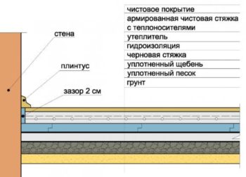 concrete floor pie
The concrete flooring pie in the house consists of:
- Compacted soil.
- A layer of rubble.
- Layers of sand bedding.
- Rough concrete screed.
- layer of insulating material.
- Reinforced cement-sand screed.
- Waterproofing.
- Clean floor.
The concrete floor, including the screed on the slabs (filling), has the highest strength resource. Also, this floor is great for bathrooms, bathrooms and other rooms where ceramic tiles are laid on the floor.
The statement that concrete flooring is always cold is incorrect if 15 cm of insulation is placed in the floor pie. Polystyrene is used at an affordable cost without fear for human health. The material withstands the temperature environment without destruction.
wood floor
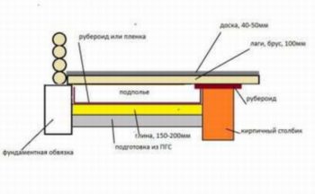 Scheme of a wooden floor pie
The floor made on the ground is made of wood, and its structure consists of:
- a small foundation for posts;
- waterproofing layer (roofing material is more often used);
- foundation pillars:
- cranial bar;
- steel mesh;
- windproof layer;
- wooden logs;
- insulating material;
- ventilation gap for the waste of moisture;
- vapor barrier layer;
- plank flooring.
During the construction of such a floor, the cross system of the wooden floor lag device makes it possible to lay insulating material of sufficient thickness, so the floor will be warm, and the tree has poor thermal conductivity. Such a floor, of course, cannot be called simple, reliable, since wood is afraid of high humidity, condensation, ages, loses its appearance. The naturalness of materials is considered a big plus, but this is not always considered an argument for its use.
Stages of laying the floor
To install a concrete floor on the ground with your own hands, you need to understand the technology and the main stages of work. Let's proceed to the direct laying of the floor on the ground in the house, which consists of the following steps:
- First you need to level the base. In this case, we will use laser and optical levels. After the relief and the level of the floor surface are determined, it is necessary to compact the soil base. For these purposes, there are special ramming machines.
- The next layer will be a layer of fine sand. It also needs to be sealed. To do this, we first moisten the sand, and then we compact it.
- For the best sand compaction, the next layer is needed. Sprinkle the sand with gravel or expanded clay.
- The next step will be laying the waterproofing membrane. It is necessary to prevent moisture from entering the soil or from the concrete screed.For waterproofing, we need a plastic film, polymer membranes or rolled bituminous materials. When laying the selected material, be sure to leave excess (20 cm), which are cut off after laying. We will fasten the material with construction tape.
- The rough concrete layer is laid quite simply. For a typical private house, the layer thickness should be approximately 5 centimeters. After laying, it is necessary to level the concrete well, the surface difference should not exceed 4 mm. Such a thin layer is laid because the rough concrete screed is intended to serve as the basis for waterproofing and vapor barrier materials.
- After the rough concrete layer, it is necessary to lay the vapor barrier material. Such materials include fiberglass or polyester membranes, polymer-bitumen materials and PVC membranes. The latter material is the highest quality and durable.
- Next, we insulate the floor in the house. First, it is necessary to analyze the surface for heat resistance in order to select a material for floor insulation. For these purposes, use foam or mineral wool. In any case, both above and below the material is covered with a plastic film.
- Well, the final stage is the laying of a clean reinforced screed. To begin with, we will reinforce the layer with a reinforcing mesh or a frame of rods. Then we fill it with concrete to half the level, make small mounds out of it and install beacon rails. Then pour the remaining concrete mixture above the level by 3 centimeters and level the surface. Now you can lay the flooring in the house.
As you can see, the installation of a concrete floor on the ground, although it is a laborious process, all the steps are simple and understandable, so this stage of work can be done by hand.
In most cases, neither the type of soil, nor seismic, nor the level of freezing affect the concrete floor in a private house. There is only one exception - this is the impossibility of its construction at a sufficiently high level of groundwater. In general, this type of floor on the ground is universal, and is often used in construction.
7 Thermal engineering calculation of light openings
V
practice of construction of residential and
public buildings applied
single, double and triple glazing
in wood, plastic or
metal bound, twin
or separate. Thermal engineering calculation
balcony doors and light fillings
openings, as well as the choice of their designs
carried out depending on the area
construction and premises.
Required
thermal total resistance
heat transfer
 ,
,
(m2 С)/W,
for light openings are determined in
depending on the value of Dd
(table 10).
Then
by value

choose
the design of the light opening with the reduced
heat transfer resistance
 provided
 ≥
≥
(table 13).
table
13 - Actual reduced resistance
windows, balcony doors and skylights
|
filling |
Reduced |
|
|
v |
v |
|
|
single |
0,18 |
− |
|
single |
0,15 |
− |
|
double glazing bindings |
0,4 |
− |
|
double glazing bindings |
0,44 |
0,34* |
|
Blocks |
0.31 (without binding) |
|
|
244 |
0.33 (without binding) |
|
|
Profile |
0.31 (without binding) |
|
|
Double |
0,36 |
− |
 ,
,
Table continuation
13
|
filling |
Reduced |
|
|
v |
v |
|
|
triple out skylights |
0,52 |
− |
|
Triple |
0,55 |
0,46 |
|
single chamber
out of the ordinary |
0,38 |
0,34 |
|
glass with coated |
0,51 |
0,43 |
|
glass with coated |
0,56 |
0,47 |
|
Double chamber
out of the ordinary |
0,51 |
0,43 |
|
out of the ordinary |
0,54 |
0,45 |
|
glass with coated |
0,58 |
0,48 |
|
glass with coated |
0,68 |
0,52 |
|
glass with
coated |
0,65 |
0,53 |
|
Normal
out of the ordinary |
0,56 |
− |
|
glass with coated |
0,65 |
− |
|
glass with
coated |
0,69 |
− |
|
Normal |
0,68 |
− |
|
glass with coated |
0,74 |
− |
|
glass with coated |
0,81 |
−* |
|
glass with
coated |
0,82 |
− |
 ,
,Continuation
tables 13
|
filling |
Reduced |
|
|
v |
v |
|
|
Two single chamber
paired |
0,7 |
− |
|
Two single chamber
separate |
0,74 |
− |
|
Four-layer
paired |
0,8 |
− |
|
Notes: * - |
 ,
,
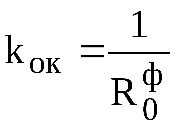
For
accepted design of the light opening
heat transfer coefficient kOK,
W/(m2 С),
is determined by the equation:
 .
.
Example
5. Thermotechnical calculation of light
openings
Initial
data.
-
Building
residential, tv
= 20С
(table
1). -
District
construction -
Penza. -
txp(0.92)
\u003d -29С;
top
= -3.6С;
zop
= 222 days (Appendix A, Table A.1);
 C day
C day
Order
calculation.
-
We define
=
0.43 (m2 С)/W,
(table 10). -
Choose
window design (table 13) depending on
from the valuetaking into account the fulfillment of condition (7). So
Thus, for our example, we take
wooden double glazed window
separate bindings, with the actual
heat transfer resistance
= 0.44 (m2 С)/W.
Coefficient
heat transfer glazing (windows) kOK
determined by
formula:
 W/(m2 C).
P.S. 02/25/2016
Almost a year after writing the article, we managed to deal with the questions raised a little higher.
Firstly, the program for calculating heat losses in Excel according to the method of A.G. Sotnikova thinks everything is correct - exactly according to the formulas of A.I. Pehovich!
Secondly, the formula (3) from the article by A.G. Sotnikova should not look like this:
R
27
=
δ
conv.
/(2*λ gr
)=K(cos
((h
H
)*(π/2)))/К(sin
((h
H
)*(π/2)))
In the article by A.G. Sotnikova is not a correct entry! But then the graph is built, and the example is calculated according to the correct formulas!!!
So it should be according to A.I. Pekhovich (p. 110, additional task to item 27):
R
27
=
δ
conv.
/λ gr
=1/(2*λ gr
)*TO(cos
((h
H
)*(π/2)))/К(sin
((h
H
)*(π/2)))
δ
conv.
=R
27
*λ gr
=(½)*K(cos
((h
H
)*(π/2)))/К(sin
((h
H
)*(π/2)))
Previously, we calculated the heat loss of the floor on the ground for a house 6m wide with a groundwater level of 6m and +3 degrees in depth. The results and problem statement are here -
The heat losses to the outdoor air and deep into the earth were also taken into account. Now I will separate the flies from the cutlets, namely, I will carry out the calculation purely into the ground, excluding heat transfer to the outside air.
I will carry out calculations for option 1 from the previous calculation (without insulation). and the following data combinations
1. UGV 6m, +3 on UGV
2. UGV 6m, +6 on UGV
3. UGV 4m, +3 on UGV
4. UGV 10m, +3 on UGV.
5. UGV 20m, +3 on UGV.
Thus, we will close the issues related to the influence of the GWL depth and the influence of temperature on the GWL.
The calculation, as before, is stationary, not taking into account seasonal fluctuations, and generally not taking into account the outside air
The conditions are the same. The ground has Lamda=1, walls 310mm Lamda=0.15, floor 250mm Lamda=1.2.
The results, as before, in two pictures (isotherms and "IK"), and numerical - resistance to heat transfer into the soil.
Numerical results:
1.R=4.01
2. R \u003d 4.01 (Everything is normalized for the difference, otherwise it should not have been)
3.R=3.12
4.R=5.68
5.R=6.14
About the sizes. If we correlate them with the GWL depth, we get the following
4m. R/L=0.78
6m. R/L=0.67
10m. R/L=0.57
20m. R/L=0.31
R / L would be equal to one (or rather, the inverse coefficient of thermal conductivity of the soil) for an infinitely large house, but in our case the dimensions of the house are comparable to the depth to which heat loss occurs, and the smaller the house compared to the depth, the smaller this ratio should be.
The resulting dependence R / L should depend on the ratio of the width of the house to the groundwater level (B / L), plus, as already mentioned, with B / L-> infinity R / L-> 1 / Lamda.
In total, there are the following points for an infinitely long house:
L/B | R*lamda/L
0 | 1
0,67 | 0,78
1 | 0,67
1,67 | 0,57
3,33 | 0,31
This dependence is well approximated by an exponential one (see the graph in the comments).
Moreover, the exponent can be written in a simpler way without much loss of accuracy, namely
R*Lambda/L=EXP(-L/(3B))
This formula at the same points gives the following results:
0 | 1
0,67 | 0,80
1 | 0,72
1,67 | 0,58
3,33 | 0,33
Those. error within 10%, i.e. very satisfactory.
Hence, for an infinite house of any width and for any GWL in the considered range, we have a formula for calculating the resistance to heat transfer in the GWL:R=(L/lamda)*EXP(-L/(3B))
here L is the depth of the GWL, Lamda is the thermal conductivity of the soil, B is the width of the house.
The formula is applicable in the L/3B range from 1.5 to approximately infinity (high GWL).
If you use the formula for deeper groundwater levels, then the formula gives a significant error, for example, for a 50m depth and 6m width of a house, we have: R=(50/1)*exp(-50/18)=3.1, which is obviously too small.
Have a good day everyone!
Conclusions:
1. An increase in the GWL depth does not lead to a consistent decrease in heat loss to groundwater, since an increasing amount of soil is involved.
2. At the same time, systems with a GWL of the type 20m or more may never reach the hospital, which is calculated during the period of "life" at home.
3. R into the ground is not so great, it is at the level of 3-6, so the heat loss deep into the floor along the ground is very significant. This is consistent with the previously obtained result about the absence of a large reduction in heat loss when the tape or blind area is insulated.
4. A formula has been derived from the results, use it to your health (at your own peril and risk, of course, I ask you to know in advance that I am in no way responsible for the reliability of the formula and other results and their applicability in practice).
5. Follows from a small study conducted below in the commentary. Heat loss to the street reduces heat loss to the ground.
Those. It is incorrect to consider two heat transfer processes separately. And by increasing the thermal protection from the street, we increase heat loss to the ground
and thus it becomes clear why the effect of warming the contour of the house, obtained earlier, is not so significant.