How to connect a generator for home
One of the burning issues after the purchase of a power plant (generator) is the choice of the correctness and sequence of actions when connecting the specified equipment. At first glance, this is a difficult task, but upon closer examination, it turns out that it is not so difficult and you can do everything yourself. That is, connect a diesel generator with your own hands, improve your home.
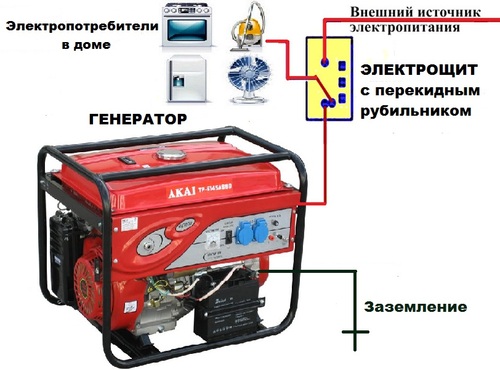
Connecting the generator to the network of a country house: you can connect a diesel-powered generator using either a manual switch or a power plant with an automatic transfer switch (ATS) automatically. A power plant with an ATS allows you to get rid of many of the inconveniences associated with running around to the power plant and planting it manually, but it is not a cheap pleasure. All you need is to be patient after turning off the light for a few seconds in order for the diesel generator to turn on and the light to come on. When the voltage in the external network appears, the specified power plant turns off by itself.
Important note. Connecting a diesel generator should only be done with a complete disconnect from the existing power supply.
This means that the phase and zero are disabled.
Some of the simplest and cheapest ways to connect a power plant to your home are as follows:
- connection through a changeover switch;
— connection through a three-way reversing switch.
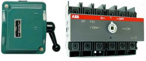
It is important to know that the changeover switch is mounted separately, and the three-way reversing switch is mounted on a special DIN rail, which is located on the electrical panel. Important note
If the network is single-phase, a two-pole switch is used (phase and zero). If the network is three-phase, a four-pole knife switch is used (phase A-B-C and zero)
Important note. If the network is single-phase, a two-pole switch is used (phase and zero)
If the network is three-phase, a four-pole knife switch is used (phase A-B-C and zero).
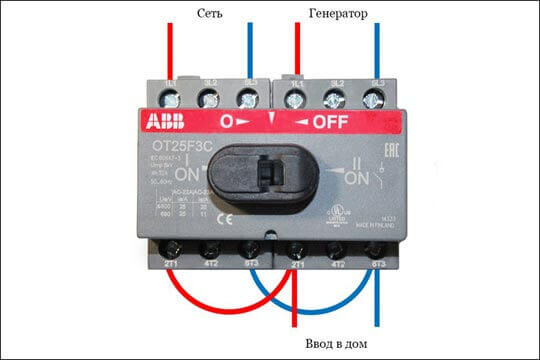
Connection through a changeover and three-way reversing switch is made using three lines, namely:
- line from the existing network;
- line from the power plant;
- a line going to energy consumers.
With this connection, three situations are possible:
- Power is supplied from the existing network;
- power is supplied from the power plant;
- power off.
Line connection diagram using a toggle switch:
1. The top contacts are used to connect to an existing network line.
2. Middle contacts are used to connect power consumers to the line.
3. The bottom contacts are used to connect to the power plant line.
The line connection diagram using a three-way switch is made taking into account the operating instructions.
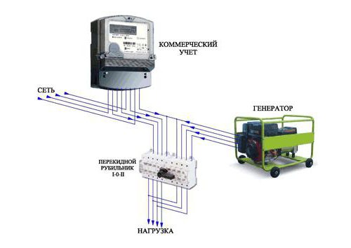
Diesel generator and its connection diagram
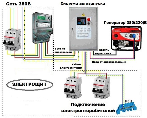
The connection is made in full accordance with the instruction manual for the equipment. At the same time, an external power supply is connected to the power plant with ATS through a meter, as well as a power cable coming from a diesel generator. From the power plant with ATS, the power cable comes out through the electrical panel, bypassing the meter.
Thus, the article discusses various ways to connect a diesel power station to a house with your own hands.
At the same time, special attention is paid to both the simplest, cheapest ways to connect a power plant to a house using changeover and three-way reversing switches, and more expensive ones - using a power plant with an automatic transfer switch.
Installation Recommendations
For safe and correct use of the device, the following recommendations must be observed:
- it is necessary to install the device indoors;
- the device must be protected from moisture, as well as from bad climatic conditions;
- the required temperature of the operating environment of the device ranges from -40 to +55 degrees;
- in case of burning of the upper part of the contact knife, it is necessary to clean it with a file;
- the appliance must be securely and firmly installed.
If the changeover switch is installed outdoors, it must be protected from environmental influences. It is also necessary to ensure the operation of the device within the permissible temperature range - that is, if outdoors, then it is necessary to ensure the heating of the cabinet where this switch is installed. Installation, maintenance and repair of the device should be carried out only by a specialist, and only when the mains is completely de-energized.
Finally, we recommend watching the video, which tells in more detail how to connect the changeover switch to the network:
It will be useful to read:
- How to install a diesel generator
- How to connect a three-phase voltage regulator
- Connecting the generator to the network at home
- What is a load switch for?
A toggle switch is a special device designed to switch electricity to the necessary devices, operating using a manual drive. Manufacturers offer a wide range of such devices, differing among themselves in various technical characteristics.
It is important to remember that there are various options for connecting changeover switches - the choice depends on the characteristics of the electrical network. The most popular change-over type switches in residential buildings
To change the performance of such devices, control units are used.
In addition, these devices have found application in industry during the operation of backup generators. When choosing a changeover switch for a generator, you need to take into account its configuration and the specifics of the existing grounding.
The quality of the device is ensured by equipping it with a ground electrode. Its marking indicates the degree of protection. It is optimal if it is IP30.
Wiring diagram
Changeover switches come in different types: single-pole, two-pole, three-pole and four-pole. The first two versions are used in a single-phase network, the other two - in a three-phase network.
These devices are connected to the generator based on the type of electrical network to which the breaker will be connected. For a single-phase network, a two-pole device is used, which simultaneously switches the zero and phase of the wiring, excluding the combination of the generator output voltage and the voltage that is supplied from the mains. A single-pole changeover switch can only be used to switch power between two phases of the same electrical network, where the neutral conductor is common and there is no need to switch it with switching devices.
If the generator and the mains supplying the house are three-phase, then in this case a four-pole switch is used, which switches three phases and zero between the main network and the backup network from the generator. Three-pole switching devices are used in circuits supplying a three-phase load without a neutral wire. Also, a three-pole device can be used in a single-phase network - in this case, only two poles will be used at the input and output of the switching device.
Changeover switches are installed in switchboards, the type of which depends on the design of the switch. There are modular type devices that are installed on a standard DIN rail. In the premises, plastic shields (boxes) or metal housings of shields, designed for the required number of modular places, can be used.

Outdoors, metal shields are used that have a degree of protection of the case sufficient for installation on the street. Change-over knife switches of the usual design are mounted in shields, completed with a mounting panel.

A standard DIN-rail can also be mounted on the mounting plate of such a shield to install the necessary modular protective devices.
A cable coming from the metering board is connected to one input of the changeover switch - this is the main network. A backup network is connected to the second input - a cable from the generator. If the switch has one output, then the cable from the switchboard is connected to it. Modular versions, as a rule, have two inputs and two outputs, so the two outputs are interconnected in parallel with jumpers and connected to the switchboard. Below is a diagram of a single-phase connection of a three-pole changeover switch to the generator and the electrical network:
In order to connect a changeover switch from two three-phase power sources, you need to use the following diagram: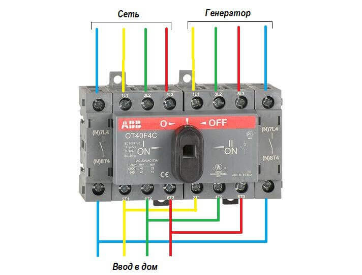 When connecting, it is necessary to observe the polarity so that when the switch is switched at the output to the home shield, the phase and zero do not change places. The input from the mains is protected by an automatic switch, which, as a rule, is installed in the metering board, and the input from the generator must be protected by an automatic switch, which is installed in the shield along with the changeover switch.
For industrial plants, devices are mounted only if the input power is small. And this is how switchboards are mainly installed - an automatic switch is installed in them for each input. Depending on the scheme, ATS operation or manual switching on of the reserve by the corresponding machine can be implemented. If at the same time changeover switches are used, then, as a rule, only for control without load - the load is removed by automatic switches.
If there is an arc-suppressing device in the design of the apparatus, the load can be switched with a changeover switch, but in any case, each of the supply lines must be additionally protected by an automatic device or fuses, since the changeover switch does not protect against emergency operation of the electrical network (overload and short circuit).
Scheme of connecting a pass-through switch from two places
Such a scheme is convenient in a two-story house on the stairs, in the passage room, in a long corridor. You can also apply it in the bedroom - turn off the overhead light at the entrance and near the bed (how many times did you have to get up to turn it on / off?).
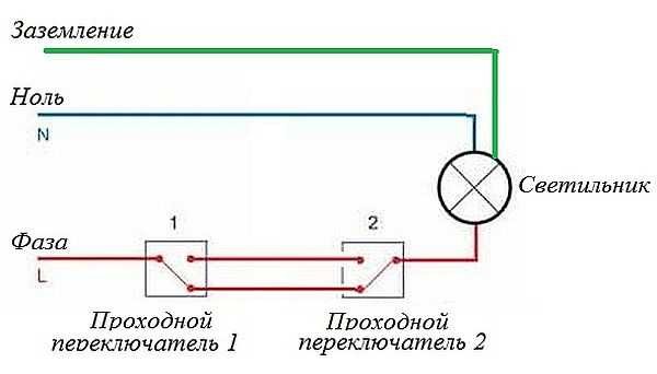
Wiring diagram for switching on the pass-through switch from 2 places
Zero and earth (if any) start up immediately on the lamp. The phase is fed to the output of the first switch, the input of the second is connected to the free wire of the lamp, the outputs of the two devices are connected to each other.
Looking at this diagram, it is easy to understand how the pass-through switch works. In the position shown in the figure, the lamp is on. By pressing the key of any of the devices, we break the chain. In the same way, in the off position, by moving any of them to another position, we will close the circuit through one of the jumpers and the lamp will light up.
To make it clearer what and with what to connect, how to lay wires, here are a few images.
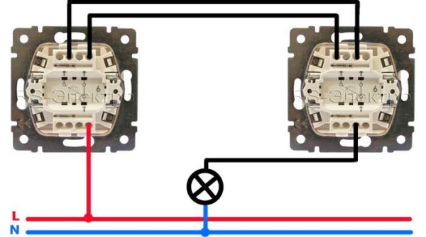
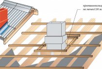
Disconnection of wires on the pass-through switch
If we talk about the room, then you need to lay the wires approximately as in the photo below. According to modern rules, they should all be located at a distance of 15 cm from the ceiling. They can be stacked in mounting boxes or trays, the ends of the wires are brought into mounting boxes. This is convenient: if necessary, you can replace the broken wire. Also, according to the latest standards, all connections occur only in junction boxes and with the help of contactors. If you make twists, then it is better to solder them, and wrap them well with electrical tape on top.
The return wire of the lamp is connected to the output of the second switch. White indicates the wires connecting the outputs of both devices.
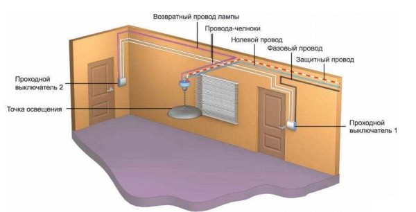
How wires are routed around the room
How to connect everything in the terminal box is described in the video.
Pass-through switches always work in pairs
Now take a look at the third option, which shows how to actually use the pass-through switches
Notice that there are two wires running between the control points. And this is a big minus for those who expected to somehow use the old veins lying in the thickness of the walls for control.
Look, now you can see that the neutral (black wire) goes straight to the chandelier. But the neutral can be broken or connected at any time from both ends of the corridor. In this case, there is always a phase on one of the wires, and you just need to feed it to the desired point. Due to which the whole problem is solved.
Now we leave the bedroom, turn on the light, get to the kitchen doorstep, and turn off the chandelier. By the way, if someone wants to join the night gatherings, then in exactly the same manner he will solve his problems without any difficulty. But what if we need to place another switch - say - in the area of \u200b\u200bthe front door?
What does a switch look like and how does it work?
If we talk about the front side, then the only difference is a barely noticeable arrow on the up and down key.

What does a single-gang switch look like? See, there are double arrows
If we talk about the electrical circuit, everything is also simple: in ordinary switches there are only two contacts, in the feed-through (also called changeover) three contacts, two of which are common. There are always two or more such devices in the circuit, and with the help of these common wires they are switched.
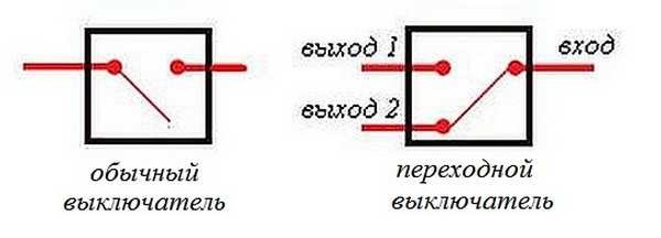
The difference is in the number of contacts
The principle of operation is simple. By changing the position of the key, the input is connected to one of the outputs. That is, these devices have only two working positions:
- input connected to output 1;
- input connected to output 2.
There are no other intermediate provisions. Thanks to this, everything works. Since the contact switches from one position to another, electricians believe that it is more correct to call them "switches". So the pass switch is also this device.
In order not to rely on the presence or absence of arrows on the keys, you need to inspect the contact part. Branded products should have a diagram that allows you to understand what type of equipment you have in your hands. It is definitely on the products of Lezard (Lezard), Legrand (Legrand), Viko (Viko). They are often absent on Chinese copies.
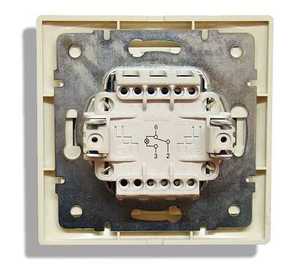
This is what the toggle switch looks like from the rear
If there is no such circuit, look at the terminals (copper contacts in the holes): there should be three of them. But not always on inexpensive specimens, the terminal that costs one is the entrance. Often they are confused. To find where the common contact is located, you need to ring the contacts among themselves at different key positions. This must be done, otherwise nothing will work, and the device itself may burn out.
You will need a tester or multimeter. If you have a multimeter, set it to sound mode - it beeps when there is a contact. If you have a pointer tester, call for a short circuit. Put the probe on one of the contacts, find which of the two it rings with (the device beeps or the arrow shows a short circuit - it deviates to the right until it stops). Without changing the position of the probes, change the position of the key. If the short circuit is missing, one of these two is common. Now it remains to check which. Without switching the key, move one of the probes to another contact. If there is a short circuit, then the contact from which the probe was not moved is the common one (this is the input).
It may become clearer if you watch a video on how to find the input (common contact) for the pass-through switch.
Connection Features
The type of electrical network influences the choice of the connection scheme for the changeover switch.
Single-phase network
It is possible to connect such a device to this network only if it has two poles. In addition, it must be taken into account that the operation of the knife switch is possible only if a power supply with suitable specifications is present. As for the jumpers that provide contact between two-pole devices, it is advisable to give preference to copper ones.
Two-phase network
How to connect a knife switch with your own hands if the network is two-phase? The circuit provides for the use of a 200V power supply. Also, for these devices, only expansion switches should be used. Only then can the devices be used in a three-phase power supply, regardless of the number of modules used.
The maximum voltage for such devices will be 300V, and the maximum negative resistance will be 40 ohms. Contacts in such devices are applicable exclusively to closed models, and fluctuations in electrical energy are controlled using pass-through capacitors.
Three-phase network
For this type of electrical network, reversing switches are used. They provide a full-fledged uninterrupted supply of electric current, distributing the load on several lines and completely preserving the power supply. Here you need to use power supplies for 400 V. It will also be appropriate to use pulse transformers.
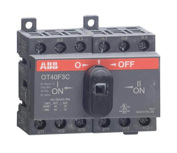
Toggle switch operating principle
An electrical type device that serves to disconnect an electrical load from one source of energy and connect it to another source is called a toggle switch, or a toggle switch (midpoint switch). Devices come with or without arc extinguishers. In the first case, network switching can occur with a fully connected load. In the second - only when it is turned off.
The operation of the circuit breaker is carried out manually, that is, if it is necessary to switch the power supply sources, the operator acts on the isolated control lever of the circuit breaker. There are also automatic switching systems.
How to make a walk-through switch with your own hands a labor lesson
You've probably looked into e-catalogues by now and noticed that a triple pass switch can cost a lot of money. What to do? - The age-old Russian question, reinterpreted by Shakespeare as to be or not to be. We would choose the first one: not everyone can definitely pay that kind of money for walk-through switches. We present to the attention of our readers the first handmade in Runet, where it will be real and the pictures show how to convert an ordinary switch costing around a hundred (this is a really cheap model) into an expensive thing - a pass-through switch. And without special skills and special techniques.
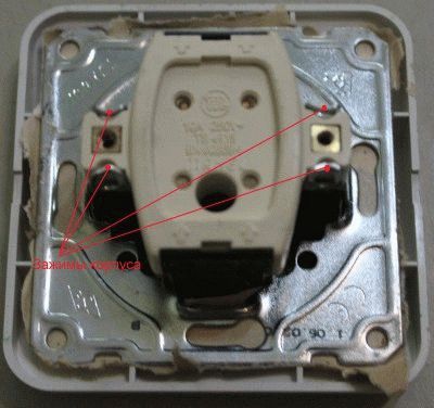
We look at the first picture and see the switch from which the buttons are removed
More precisely, it is also taken out of the socket (if I may say so), but this is not the point now. As you can see from the picture, we have here a typical 2-key connection diagram
Just in case, the screws of the spacers of the socket box and the clamping contacts of suitable wires are shown and signed with colored lines. All of them need to be significantly loosened to dismantle the switch from the wall socket. Do not forget to turn off the power before this, and we also strongly recommend checking with a probe where the phase is, and somehow draw these places directly on the cambric (plastic core insulation). In the future, all this will greatly simplify the process of reinstalling the switch.
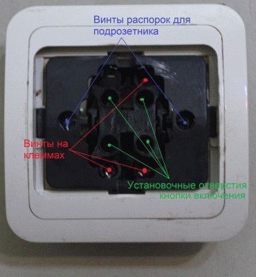
Screws for spacers
Now we look at the next picture, which shows the reverse side of our future victim. In the good sense of the word, of course. Here we see the clamps on the switch housing that need to be unbent in order to remove the electrical part.All this is done with an ordinary screwdriver within a few minutes. Then you need to get spring pushers from the plastic frame. The easiest way to do this is with a thick slotted screwdriver. The thin one just won't fit. You will quickly understand this. There is no need to rush, because this place is the most difficult in the whole process of reworking a conventional switch in the entrance. In the picture, the spring pushers have already been removed, and moving contacts are visible in the place where they were.
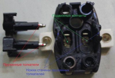
Movable contacts under spring plungers
We skipped the moment of removing the plastic part from the ceramic (in the pictures), because this, in our opinion, is self-explanatory. There are two weak teeth on the ends of the entire removed part of the switch. Just pry them off with a slotted screwdriver, and let's start reworking a regular switch in the checkpoint. Now on the ceramic base of the switch we see groups of contacts:
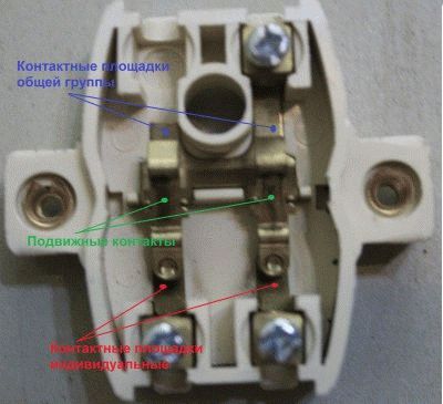
Three groups of contacts
- Contact pads of the general group.
- Individual contacts for each bulb.
- Movable rocker contacts.
Now we have one rocker to turn 180 degrees, and cut off one of the contact pads of the common group (it’s better not to isolate). The resulting position is shown in the last image. Now the final step is how it all works. We take and glue both buttons with a Chinese pistol so that they become one. Now, when one of our contacts is closed, the second will hang in the air.
Everything ingenious is simple. Therefore, in addition to the fact that we have shown how to make a pass-through switch from a conventional one, we add that in principle it is not necessary to remove the spring pushers. You can do without it. And two buttons do not have to be glued if you remove the key from a conventional switch of the same width and the same manufacturer. Usually the pinout of the legs is exactly the same there. All this will allow not only to make a pass-through switch with your own hands, but also to produce a really workable and beautiful product.
So, we believe that we have considered the questions asked in excess. They showed how to properly connect a pass-through switch, how not to do it, and - most importantly - told how you can save a lot of money on the whole process. We hope that the recommendations will be to your liking, and now every handy owner will be able to boast of having such an original design in his house. Well, what else would you call a pass switch?
Change-over type circuit breaker
All the toggle switches presented above have one drawback - they require the presence of a person to carry out manipulations with switching circuits. This is inconvenient, especially when the central power supply fails frequently and unpredictably. Therefore, a toggle circuit breaker was developed. More precisely, this is a whole block called automatic reserve transfer (ATS).
ATS is a complex design, but craftsmen assemble such systems from relatively inexpensive relay devices (contactors). For this, models with normally closed and open contacts are used.
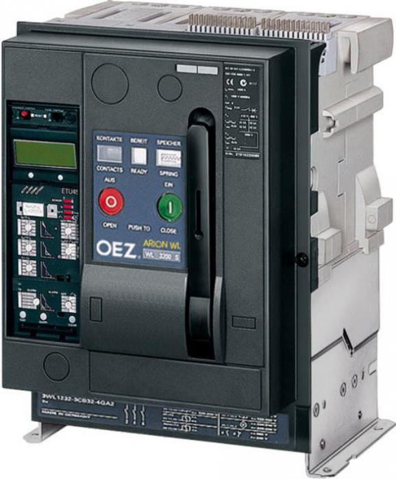
When a homemade toggle switch is used, the wiring diagram works according to a certain principle. For example, if there is central supply electricity in the line, then a relay with normally open contacts closes the circuit with the load. The relay with normally closed contacts, where the generator is connected, is open in this case. As soon as the current disappears, the combination is reversed, and the network begins to feed the generator.
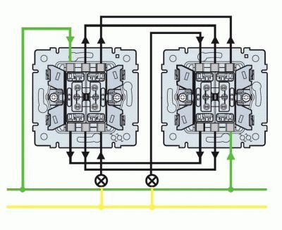
Correct connection of the toggle switch for organizing three lighting control points
In this case, a one-button walk-through switch in the amount of two pieces is combined with a toggle switch. And that's what it gives. As before, in the figure we applied two colors. Imagine that the phase is now on blue. As shown in the picture.Now it's time to go visit. And we turn off the light with one movement of the toggle switch. Really, great?
All other options work the same way. Now the light in the corridor can be turned on and off from any of the three points. Whether it's the front door, the threshold of the kitchen or the exit from the bedroom. Moreover, toggle switches can be garlanded. But they all turn on towards each other.
Thus, we get the second rule. It applies to both toggle and walk-through switches: the switches are switched on towards.
We believe that there is no need to explain these words. They can be clearly traced in the first figure, where the switches are located side by side to each other. The second one looks outward, that is, towards the power supply and the light bulb in the chandelier.
Conventional switch and walk-through
As can be seen from the figure, the through switch switches the working contact to one of their outputs. To make it easier to see, we painted the veins in different colors. In this case, it is clearly seen that at a certain position, the neutral and phase are short-circuited. And this is a fire, knocked out traffic jams, a lot of nerves and experiences. Remember a simple rule: a pass-through switch is never placed in the same circuit as a regular one. For nothing to happen. There is, however, one working scheme using a toggle switch, which we will consider a little later (you can see the second option in advance in figure number 2).
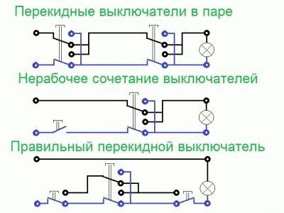
Figure 2. Working diagram using a toggle switch
When solving the issue of three illumination control points in the corridor. It flips the wires criss-cross, creating curious possibilities for organizing an infinite number of switches.
Note that despite all this neutral and phase manipulation, there is no way to create a short circuit. That is, the through switch can be used in tandem with a conventional
Here's what it might look like in real life:
- The light is extinguished, as can be seen from the figure. Because a conventional switch broke one of the wires.
- Leaving the bedroom to the kitchen, we turn on the illumination, closing the contact.
- Then we calmly go to the refrigerator (or horizontal bar - who cares).
- Having reached the threshold of the kitchen, we throw a pass-through switch, which simply changes the polarity of the phase and neutral on the light bulb.
Now there are many people who will say that this will not work, and we will answer that if the power was from direct current, and this is often found on ships, in cars and trains, then everything would be in order. It is only necessary to put a diode in the right place. As for an ordinary apartment, this combination really does not look the best.
Schematic of a toggle switch
The toggle switch consists of a housing, blade-type moving contacts mounted on the shaft, fixed contacts, a control handle, an arc chute (if present) and terminals for connecting to the line. The device has two operating positions (contacts 1 and 2) and one neutral (intermediate), in which the load is not connected to any of the lines.
A simple switching circuit for two power sources and one load line looks like this: to contacts 1, for example, the central power supply is connected, to contacts 2 - a diesel or other type of electric generator. The most popular are four-pole and two-pole switches.
The connection of the toggle switch in case of three-phase voltage input to the building is as follows:
- the switch must be four poles;
- four terminals go to the network input;
- four terminals go to the input of the generator;
- load is connected to four terminals.
Three of the four terminals go to phases, one to zero.
How to connect a pass switch
A. Zemskov has a whole video on this subject.Not to say that it was perfect, but on the whole it leaves a feeling of a complete understanding of the topic within the framework of the material taught by the author. Yes, of course, there were those who left rude remarks like the fact that such things are called switches, because they throw the ends of the chains crosswise. But we, with our readers, understand that all this is from envy. Everyone wants to see a good repair at home, but not everyone can pay for it as much as the Project-service takes. Hence the misunderstanding. As for A. Zemskov himself, in our humble opinion, the little man who managed to earn money for such a wheelbarrow legally deserves all respect. So, today we are talking about how to connect a pass-through switch.
Specifications
The main characteristics of the toggle switch are:
- The rated current that it can pass. Devices are available for 15.0, 25.0, 32.0, 40.0, 63.0, 80.0, 100.0 and 125.0 A.
- Thermal current that does not destroy elements.
- Permissible mains voltage.
- Short-term impulse voltage that the insulation can withstand.
- The number of poles that a toggle switch can simultaneously switch.
- The wear resistance of electrical contacts is determined by the operating voltage and the magnitude of the transmitted current.
- The wear resistance of mechanical elements is determined by the number of switching cycles.
Conclusion
The use of toggle switches for switching a generator is an expedient solution that allows you to have significant advantages. In addition to facilitating the process of maintenance of an individual power source, this device makes it possible to control the state of the functioning of the network and ensures the safety of the operation of all elements included in the line. To select the best option for a toggle switch, they are primarily guided by the individual characteristics of the electrical network and the devices included in it. Based on this, a toggle switch is selected with characteristics that meet such requirements.

6 Best Dog Breeds for Families with Young Children Many families decide to get a dog around the same time they have their first child. But which dog breeds are best for families.

What is it like to be the heir to the royal throne? 7 Unexpected Facts Royal heirs are entitled to a range of benefits, but until recently, these were also limited by ancient traditions formed against the backdrop.

How to inform your daughter or son that another child will appear in the family Are you expecting another child? Congratulations! You might want to share that joy with family and friends, but what about older kids? When

Why have you never seen a baby pigeon? Go to any city square and no doubt you will see hundreds of pigeons flying near passers-by. But despite such a large number of

15 most beautiful wives of millionaires Check out the list of wives of the most successful people in the world. They are stunning beauties and often successful in business.

Our ancestors slept differently than we do. What are we doing wrong? It's hard to believe, but scientists and many historians are inclined to believe that modern man sleeps in a completely different way from his ancient ancestors. Initially.