Temperature chart of the heating system - calculation procedure and ready-made tables
The basis of an economical approach to energy consumption in a heating system of any type is the temperature graph. Its parameters indicate the optimal value of water heating, thereby optimizing costs. In order to apply these data in practice, it is necessary to learn more about the principles of its construction.
Terminology
Temperature graph - the optimal value of heating the coolant to create a comfortable temperature in the room. It consists of several parameters, each of which directly affects the quality of the entire heating system.
- The temperature in the inlet and outlet pipes of the heating boiler.
- The difference between these indicators of heating the coolant.
- Temperature indoors and outdoors.
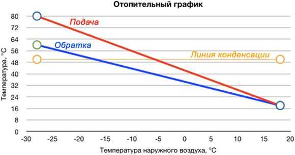
The latter characteristics are decisive for the regulation of the first two. Theoretically, the need to increase the heating of water in the pipes comes with a decrease in the temperature outside. But how much should the boiler power be increased in order for the air heating in the room to be optimal? To do this, draw up a graph of the dependence of the parameters of the heating system.
- 150°C/70°C. Before reaching the users, the coolant is diluted with water from the return pipe to normalize the incoming temperature.
- 90°C/70°C. In this case, there is no need to install equipment for mixing streams.
According to the current parameters of the system, utilities must monitor compliance with the heating value of the coolant in the return pipe. If this parameter is less than normal, it means that the room is not warming up properly. The excess indicates the opposite - the temperature in the apartments is too high.
Temperature chart for a private house
The practice of drawing up such a schedule for autonomous heating is not very developed. This is due to its fundamental difference from the centralized one. It is possible to control the water temperature in the pipes in manual and automatic mode. If the installation of sensors for automatic control of the operation of the boiler and thermostats in each room was taken into account during the design and practical implementation, then there will be no urgent need to calculate the temperature schedule.
But for calculating future expenses depending on weather conditions, it will be indispensable. In order to make it according to the current rules, the following conditions must be taken into account:
- Heat loss at home should be within normal limits. The main indicator of this condition is the heat transfer resistance coefficient of the walls. Depending on the region, it is different, but for central Russia, you can take the average value - 3.33 m² * C / W.
- Uniform heating of residential premises in the house during the operation of the heating system. This does not take into account the forced decrease in temperature in one or another element of the system. Ideally, the amount of heat energy from the heating device (radiator), as far as possible from the boiler, should be equal to that installed close to it.
Only after these conditions are met, you can proceed to the calculation part. At this stage, difficulties may arise. The correct calculation of an individual temperature graph is a complex mathematical scheme that takes into account all possible indicators.
However, to facilitate the task, there are ready-made tables with indicators. Below are examples of the most common modes of operation of heating equipment. The following input data were taken as initial conditions:
- The minimum air temperature outside is 30°С
- The optimum room temperature is +22°C.
Based on these data, schedules were drawn up for the following types of heating systems.
It is worth remembering that these data do not take into account the design features of the heating system. They only show the recommended values of temperature and power of heating equipment, depending on weather conditions.
eco-sip.ru
- putty
- building a wall
- Painting
- Wallpaper
- We decorate the walls
- facade panels
- Other materials
The speed of water movement in the pipes of the heating system.
At the lectures, we were told that the optimal speed of water in the pipeline is 0.8-1.5 m/s. On some sites I meet this (specifically, about the maximum one and a half meters per second).
BUT in the manual it is said to take losses per linear meter and speed - according to the application in the manual. There, the speeds are completely different, the maximum that is in the plate is just 0.8 m / s.
And in the textbook I met an example of calculation, where the speeds do not exceed 0.3-0.4 m / s.
So what's the point? How to accept in general (and how in reality, in practice)?
I am attaching a screenshot of the table from the manual.
Thanks for all the replies in advance!
What do you want something? “Military secret” (how to actually do it) to find out, or to pass a course paper? If only a course paper, then according to the training manual, which the teacher wrote and does not know anything else and does not want to know. And if you do how to
still won't accept.
0.036*G^0.53 - for heating risers
0.034*G^0.49 - for branch mains until the load is reduced to 1/3
0.022*G^0.49 - for end sections of a branch with a load of 1/3 of the entire branch
In the course book, I calculated it as according to the training manual. But I wanted to know how things are going.
That is, it turns out in the textbook (Staroverov, M. Stroyizdat) is also not true (speeds from 0.08 to 0.3-0.4). But perhaps there is only an example of the calculation.
Offtop: That is, you also confirm that, in fact, the old (relatively) SNiPs are in no way inferior to the new ones, and somewhere even better. (Many teachers tell us about this. According to the PSP, in general, the dean says that their new SNiP in many respects contradicts both the laws and himself).
But basically everything was explained.
and the calculation for a decrease in diameters along the flow seems to save materials. but increases labor costs for installation. If labor is cheap, maybe it makes sense. If labor is expensive, there is no point. And if on a large length (heating main) a change in diameter is beneficial, fussing with these diameters within the house does not make sense.
and there is also the concept of hydraulic stability of the heating system - and ShaggyDoc schemes win here
We disconnect each riser (upper wiring) from the main with a valve. Duck here I met that immediately after the valve they put double adjustment taps. Expedient?
And how to disconnect the radiators themselves from the connections: with valves, or with a double adjustment valve, or both? (that is, if this valve could completely block the pipeline, then the valve is then not needed at all?)
And what is the purpose of isolating sections of the pipeline? (designation - spiral)
The heating system is two-pipe.
To me specifically on the supply pipeline to find out, the question is higher.
We have a coefficient of local resistance to the flow inlet with a turn. Specifically, we apply it to the entrance through the louvered grille into the vertical channel. And this coefficient is equal to 2.5 - which is not enough.
That is, how would you come up with something to get rid of it. One of the exits is if the grate is “in the ceiling”, and then there will be no entrance with a turn (although it will still be small, since the air will be drawn along the ceiling, moving horizontally, and moving towards this grate, turn in a vertical direction, but along Logically it should be less than 2.5).
You can't make a lattice in the ceiling in an apartment building, neighbors. and in a single-family apartment - the ceiling will not be beautiful with a grate, and garbage can get in. i.e. the problem is not solved.
often I drill, then plug
Take the thermal power and the initial from the final temperature.Based on these data, you will absolutely reliably calculate
speed. It will most likely be a maximum of 0.2 m/s. Higher speeds require a pump.
Calculation of the speed of movement of the coolant in pipelines
When designing heating systems, special attention should be paid to the speed of the coolant in pipelines, since the speed directly affects the noise level. According to SP 60.13330.2012
Set of rules. Heating, ventilation and air conditioning. The updated version of SNiP 41-01-2003 maximum water velocity in the heating system is determined from the table
According to SP 60.13330.2012. Set of rules. Heating, ventilation and air conditioning. The updated version of SNiP 41-01-2003 maximum water velocity in the heating system is determined from the table.
| Permissible equivalent noise level, dBA | Permissible speed of water movement, m/s, in pipelines at coefficients of local resistance of the heater unit or riser with fittings, reduced to the velocity of the coolant in the pipes | ||||
|---|---|---|---|---|---|
| Up to 5 | 10 | 15 | 20 | 30 | |
| 25 | 1.5/1.5 | 1.1/0.7 | 0.9/0.55 | 0.75/0.5 | 0.6/0.4 |
| 30 | 1.5/1.5 | 1.5/1.2 | 1.2/1.0 | 1.0/0.8 | 0.85/0.65 |
| 35 | 1.5/1.5 | 1.5/1.5 | 1.5/1.1 | 1.2/0.95 | 1.0/0.8 |
| 40 | 1.5/1.5 | 1.5/1.5 | 1.5/1.5 | 1.5/1.5 | 1.3/1.2 |
|
Notes
|
calceng.ru
What are the consequences of narrowing the diameter of the heating pipe
Narrowing the pipe diameter is highly undesirable. When wiring around the house, it is recommended to use the same size - you should not increase or decrease it. A possible exception would be only a large length of the circulation circuit. But in this case, you need to be careful.

But in the same situation, it turns out that the residents who made such a replacement of pipes, “stole” about 40% of the heat and water passing through the pipes from their neighbors in this riser automatically. Therefore, it should be understood that the thickness of the pipes, arbitrarily replaced in a thermal system, is not a matter of a private decision, this cannot be done. If steel pipes are replaced with plastic ones, you will have to expand the holes in the ceilings, whatever one may say.
There is another option in this situation. When replacing risers in old holes, it is possible to skip new segments of steel pipes of the same diameter, their length will be 50-60 cm (this depends on such a parameter as the thickness of the ceiling). And then they are connected by couplings with plastic pipes. This option is quite acceptable.
The nuances that you need to know about to perform a hydraulic calculation of a radiator heating system.
Comfort in a country house largely depends on the reliable operation of the heating system. Heat transfer during radiator heating, the "warm floor" and "warm plinth" systems is ensured by the movement of the coolant through the pipes. Therefore, the correct selection of circulation pumps, shut-off and control valves, fittings and the determination of the optimal diameter of pipelines is preceded by a hydraulic calculation of the heating system.
This calculation requires professional knowledge, so we are in this part of the training course "Heating systems: selection, installation"
, with the help of a REHAU specialist, we will tell you:
- What nuances should be known before performing a hydraulic calculation.
- What is the difference between heating systems with dead-end and passing movement of the coolant.
- What are the goals of hydraulic calculation.
- How the material of the pipes and the way they are connected affects the hydraulic calculation.
- How special software allows you to speed up and simplify the process of hydraulic calculation.
Data how to calculate the diameter of the pipe for heating
To calculate the diameter of the pipeline, you will need the following data: these are the total heat loss of the dwelling, the length of the pipeline, and the calculation of the power of the radiators of each room, as well as the wiring method. Divorce can be single-pipe, two-pipe, have forced or natural ventilation.
Unfortunately, it is impossible to accurately calculate the cross section of pipes. One way or another, you will have to choose from a couple of options. This point should be clarified: a certain amount of heat must be delivered to the radiators, while achieving uniform heating of the batteries. If we are talking about systems with forced ventilation, then this is done using pipes, a pump and the coolant itself. All that is needed is to drive the required amount of coolant for a certain time period.
It turns out that you can choose pipes of smaller diameter, and supply the coolant at a higher speed. You can also make a choice in favor of pipes of a larger cross section, but reduce the intensity of the coolant supply. The first option is preferred.
The influence of temperature on the properties of the coolant
In addition to the above factors, the temperature of the water in the heat supply pipes affects its properties. This is the principle of operation of gravitational heating systems. With an increase in the level of heating of water, it expands and circulation occurs.

Heat transfer fluids for the heating system
However, in the case of using antifreezes, the excess temperature in the radiators can lead to other results. Therefore, for heat supply with a coolant other than water, you must first find out the permissible indicators of its heating. This does not apply to the temperature of district heating radiators in the apartment, since antifreeze-based fluids are not used in such systems.
Antifreeze is used if there is a possibility of low temperature affecting the radiators. Unlike water, it does not begin to change from a liquid to a crystalline state when it reaches 0°C. However, if the work of heat supply is outside the norms of the temperature table for heating upwards, the following phenomena may occur:
- Foaming. This entails an increase in the volume of the coolant and, as a consequence, an increase in pressure. The reverse process will not be observed when the antifreeze cools;
- Formation of limescale. The composition of antifreeze includes a certain amount of mineral components. If the norm of the heating temperature in the apartment is violated in a big way, their precipitation begins. Over time, this will lead to clogging of pipes and radiators;
- Increasing the density index. There may be malfunctions in the operation of the circulation pump if its rated power was not designed for the occurrence of such situations.
Therefore, it is much easier to monitor the temperature of the water in the heating system of a private house than to control the degree of heating of antifreeze. In addition, ethylene glycol-based compounds emit a gas harmful to humans during evaporation. Currently, they are practically not used as a heat carrier in autonomous heat supply systems.
Before pouring antifreeze into the heating, all rubber gaskets should be replaced with paranitic ones. This is due to the increased permeability of this type of coolant.
Coolant flow in the heating system
The flow rate in the heat carrier system means the mass amount of heat carrier (kg / s) intended to supply the required amount of heat to the heated room.Calculation of the coolant in the heating system is defined as the quotient of the calculated heat demand (W) of the room (rooms) divided by the heat output of 1 kg of coolant for heating (J / kg).
Some tips for filling the heating system with coolant in the video:
The coolant flow in the system during the heating season in vertical central heating systems changes as they are regulated (this is especially true for the gravitational circulation of the coolant - in more detail: "Calculation of the gravitational heating system of a private house - scheme"). In practice, in calculations, the flow rate of the coolant is usually measured in kg / h.
Goals of hydraulic calculation
The objectives of hydraulic calculation are as follows:
- Select the optimal diameters of pipelines.
- Link the pressures in the individual branches of the network.
- Select a circulation pump for the heating system.
Let's explore each of these points in more detail.
1.
Selection of pipeline diameters
If the system is branched - there is a short and a long branch, then there is a large flow on the long branch, and less on the short branch. In this case, the short branch must be made from pipes of smaller diameters, and the long branch must be made from pipes of a larger diameter.
And, as the flow rate decreases, from the beginning to the end of the branch, the diameters of the pipes should decrease so that the coolant velocity is approximately the same.
2.
Linking pressures in individual branches of the network
Linkage can be carried out by selecting the appropriate pipe diameters or, if the possibilities of this method have been exhausted, then by installing pressure flow regulators or control valves on separate branches.
Adjustment fittings may be different.
Budget option - we put a control valve - i.e. a continuously adjustable valve that has a gradation in the setting. Each valve has its own characteristics. In the hydraulic calculation, the designer looks at how much pressure needs to be relieved, and the so-called pressure discrepancy between the long and short branches is determined. Then, according to the characteristics of the valve, the designer determines how many revolutions this valve, from a fully closed position, will need to be opened. For example, 1, 1.5 or 2 turns. Depending on the degree of opening of the valve, different resistance will be added.
A more expensive and complex version of control valves - the so-called. pressure regulators and flow regulators. These are devices on which we set the required flow rate or the required pressure drop, i.e. drop in pressure on this branch. In this case, the devices themselves control the operation of the system and, if the flow rate does not meet the required level, they open the section, and the flow rate increases. If the flow rate is too high, then the cross section is blocked. The same happens with pressure.
If all consumers, after a nightly decrease in heat transfer, simultaneously opened their heating devices in the morning, then the coolant will try, first of all, to enter the devices closest to the heating point, and reach the distant ones after hours. Then the pressure regulator will work, covering the nearest branches and, thereby, ensuring a uniform supply of coolant to all branches.
3.
Selection of a circulation pump by pressure (head) and flow (flow)
If there are several circulation pumps in the system, then if they are installed in series, the pressure is summed up, and the flow rate will be total. If the pumps work in parallel, then their flow is summed up, and the pressure will be the same.
Important: Having determined the pressure loss in the system during the hydraulic calculation, you can select a circulation pump,
which will optimally match the parameters of the system, providing the optimum cost - capital (the cost of the pump) and operating (the cost of electricity for circulation)
Optimal values in an individual heating system
 Autonomous heating helps to avoid many problems that arise with a centralized network, and the optimal temperature of the coolant can be adjusted according to the season. In the case of individual heating, the concept of norm includes the heat transfer of a heating device per unit area of the room where this device is located. The thermal regime in this situation is provided by the design features of the heating devices.
It is important to ensure that the heat carrier in the network does not cool below 70 ° C. 80 °C is considered optimal
It is easier to control heating with a gas boiler, because manufacturers limit the possibility of heating the coolant to 90 ° C. Using sensors to adjust the gas supply, the heating of the coolant can be controlled.
A little more difficult with solid fuel devices, they do not regulate the heating of the liquid, and can easily turn it into steam. And it is impossible to reduce the heat from coal or wood by turning the knob in such a situation. At the same time, the control of heating of the coolant is rather conditional with high errors and is performed by rotary thermostats and mechanical dampers.
Electric boilers allow you to smoothly adjust the heating of the coolant from 30 to 90 ° C. They are equipped with an excellent overheating protection system.
Coordination of water temperature in the boiler and system
There are two options for coordinating high-temperature coolants in the boiler and lower temperatures in the heating system:
- In the first case, the efficiency of the boiler should be neglected and, at the exit from it, the coolant should be given out to such a degree of heating that the system currently requires. This is how small boilers operate. But in the end, it turns out not always to supply the coolant in accordance with the optimal temperature regime according to the schedule (read: “Heating season schedule - beginning and end of the season“). Recently, more and more often, in small boiler rooms, a water heating regulator is mounted at the outlet, taking into account the readings, which fixes the coolant temperature sensor.
- In the second case, the heating of water for transportation through networks at the outlet of the boiler room is maximized. Further, in the immediate vicinity of consumers, the temperature of the coolant is automatically controlled to the required values. This method is considered more progressive, it is used in many large heating networks, and since regulators and sensors have become cheaper, it is increasingly used in small heat supply facilities.
Temperature norms

- DBN (B. 2.5-39 Heat networks);
- SNiP 2.04.05 "Heating, ventilation and air conditioning".
For the calculated temperature of the water in the supply, the figure is taken that is equal to the temperature of the water at the outlet of the boiler, according to its passport data.
For individual heating, it is necessary to decide what the temperature of the coolant should be, taking into account such factors:
- 1 Beginning and end of the heating season according to the average daily temperature outside +8 °C for 3 days;
- 2 The average temperature inside the heated premises of housing and communal and public importance should be 20 °C, and for industrial buildings 16 °C;
- 3 The average design temperature must comply with the requirements of DBN V.2.2-10, DBN V.2.2.-4, DSanPiN 5.5.2.008, SP No. 3231-85.
According to SNiP 2.04.05 "Heating, ventilation and air conditioning" (clause 3.20), the coolant limit values are as follows:
- 1 For a hospital - 85 °C (excluding psychiatric and drug departments, as well as administrative or domestic premises);
- 2 For residential, public, as well as domestic buildings (excluding halls for sports, trade, spectators and passengers) - 90 ° С;
- 3 For auditoriums, restaurants and production facilities of category A and B - 105 °C;
- 4 For catering establishments (excluding restaurants) - this is 115 °С;
- 5 For production premises (categories C, D and D), where combustible dust and aerosols are emitted - 130 ° C;
- 6 For stairwells, vestibules, pedestrian crossings, technical premises, residential buildings, industrial premises without flammable dust and aerosols - 150 °С.
Depending on external factors, the water temperature in the heating system can be from 30 to 90 °C. When heated above 90 ° C, dust and paintwork begin to decompose. For these reasons, sanitary standards prohibit more heating.
To calculate the optimal indicators, special graphs and tables can be used, in which the norms are determined depending on the season:
- With an average value outside the window of 0 °С, the supply for radiators with different wiring is set at a level of 40 to 45 °С, and the return temperature is from 35 to 38 °С;
- At -20 °С, the supply is heated from 67 to 77 °С, while the return rate should be from 53 to 55 °С;
- At -40 ° C outside the window for all heating devices set the maximum allowable values. At the supply it is from 95 to 105 ° C, and at the return - 70 ° C.
The wiring diagram of the heating system and the diameter of the pipes for heating
The heating wiring diagram is always taken into account. It can be two-pipe vertical, two-pipe horizontal and one-pipe. A two-pipe system involves both upper and lower placement of highways. But the single-pipe system takes into account the economical use of the length of the pipelines, which is suitable for heating with natural circulation. Then the two-pipe will require the mandatory inclusion of the pump in the circuit.
There are three types of horizontal wiring:
- dead end;
- Beam or collector;
- With parallel movement of water.
By the way, in the scheme of a single-pipe system there may be a so-called bypass pipe. It will become an additional line for fluid circulation if one or more radiators are turned off. Usually, shut-off valves are installed on each radiator, which allow you to shut off the water supply if necessary.
Coolant speed
Schematic calculation
There is a minimum speed of hot water inside the heating system, at which the heating itself works optimally. This is 0.2-0.25 m / s. If it decreases, then air begins to be released from the water, which leads to the formation of air pockets. Consequences - heating will not work, and the boiler will boil.
This is the lower threshold, and as for the upper level, it should not exceed 1.5 m / s. Exceeding threatens the appearance of noise inside the pipeline. The most acceptable indicator is 0.3-0.7 m / s.
If you need to accurately calculate the speed of water movement, you will have to take into account the parameters of the material from which the pipes are made. Especially in this case, the roughness of the inner surfaces of the pipes is taken into account.
For example, hot water moves at a speed of 0.25-0.5 m/s through steel pipes, 0.25-0.7 m/s through copper pipes, and 0.3-0.7 m/s through plastic pipes.
The principle of operation of heating regulators
The temperature regulator of the coolant circulating in the heating system is a device that provides automatic control and adjustment of the temperature parameters of the water.
This device, shown in the photo, consists of the following elements:
- computing and switching node;
- operating mechanism on the hot coolant supply pipe;
- an actuating unit designed to mix in the coolant coming from the return. In some cases, a three-way valve is installed;
- booster pump in the supply area;
- not always a booster pump in the "cold bypass" segment;
- sensor on the coolant supply line;
- valves and stop valves;
- return sensor;
- outdoor air temperature sensor;
- several room temperature sensors.
Now it is necessary to understand how the temperature of the coolant is regulated and how the regulator functions.
At the outlet of the heating system (return), the temperature of the coolant depends on the volume of water that has passed through it, since the load is relatively constant. Covering the liquid supply, the regulator thereby increases the difference between the supply line and the return line to the required value (sensors are installed on these pipelines).
When, on the contrary, it is necessary to increase the flow of the coolant, then a booster pump is inserted into the heat supply system, which is also controlled by the regulator. In order to lower the temperature of the water inlet flow, a cold bypass is used, which means that part of the heat carrier that has already circulated through the system is again sent to the inlet.
As a result, the regulator, redistributing the heat carrier flows depending on the data recorded by the sensor, ensures compliance with the temperature schedule of the heating system.
Often, such a controller is combined with a hot water controller using one computing node. A device that regulates hot water supply is easier to manage and in terms of actuators. With the help of a sensor on the hot water supply line, the passage of water through the boiler is adjusted and as a result it steadily has a standard 50 degrees (read: “Heating through a water heater“).
Recommendations for selection and operation
When choosing a coolant for a heating system, it is worth knowing that not all heating systems are able to work with antifreeze. Many manufacturers do not allow the possibility of using it as a coolant, often this is the reason for refusing warranty service for equipment.
Before filling the heating system with coolant, you need to carefully study its features, such as:
- composition, purpose and types of additives;
- freezing point;
- duration of operation without replacement;
- interaction of antifreeze with rubber, plastic, metal, etc.;
- health and environmental safety (replacing the coolant in the system will require draining it).
The lower surface tension coefficient than that of water gives it fluidity and allows it to easily penetrate into pores and microcracks. All connections must be sealed with Teflon, paronite or resistant rubber gaskets. It makes no sense to use elements with zinc coating in the heating system. As a result of a chemical reaction, it will be destroyed during the first heating season.
The calculation shows that due to the low heat capacity, antifreeze accumulates and releases heat energy more slowly, so it is necessary to use pipes with an increased diameter and increase the number of radiator sections. The circulation of the coolant in the system is hampered by the increased viscosity of the antifreeze, which reduces the efficiency. This is eliminated by replacing the pump with a more powerful one.
A preliminary calculation will help to correctly design the heating circuit and will allow you to find out the required volume of coolant in the system.
It is unacceptable to exceed the temperature of the coolant in the heating system more than that declared by the manufacturer. Even a short-term increase in the temperature of the coolant worsens its parameters, leads to the decomposition of additives and the appearance of insoluble formations in the form of sediment and acids. When sediment gets on the heating elements, soot occurs. Acids, reacting with metals, contribute to the formation of corrosion.
The service life of antifreeze depends solely on the selected mode and is 3-5 years (up to 10 seasons). Before replacing it, it is necessary to flush the entire system and the boiler with water.
Conclusion
Heating in the house
So let's sum it up. As you can see, in order to make a hydraulic analysis of the heating system at home, a lot needs to be taken into account.The example was deliberately simple, since it is very difficult to figure out, say, a two-pipe heating system for a house with three or more floors. To conduct such an analysis, you will have to contact a specialized bureau, where professionals will sort everything “by the bones”.
It will be necessary to take into account not only the above indicators. This will have to include pressure loss, temperature drop, circulation pump power, system operation mode, and so on. There are many indicators, but all of them are present in GOSTs, and the specialist will quickly figure out what's what.
The only thing that needs to be provided for the calculation is the power of the heating boiler, the diameter of the pipes, the presence and number of valves and the power of the pump.
In order for the water heating system to function correctly, it is necessary to ensure the desired coolant velocity in the system. If the speed is low, the heating of the room will be very slow and the distant radiators will be much colder than the near ones. On the contrary, if the speed of the coolant is too high, then the coolant itself will not have time to heat up in the boiler, the temperature of the entire heating system will be lower. Added to the noise level. As you can see, the speed of the coolant in the heating system is a very important parameter. Let's take a closer look at what should be the most optimal speed.
Heating systems where natural circulation occurs, as a rule, have a relatively low coolant velocity. The pressure drop in the pipes is achieved by the correct location of the boiler, the expansion tank and the pipes themselves - straight and return. Only the correct calculation before installation allows you to achieve the correct, uniform movement of the coolant. But still, the inertia of heating systems with natural fluid circulation is very large. The result is slow heating of the premises, low efficiency. The main advantage of such a system is the maximum independence from electricity, there are no electric pumps.
Most often, houses use a heating system with forced circulation of the coolant. The main element of such a system is a circulation pump. It is he who accelerates the movement of the coolant, the speed of the liquid in the heating system depends on its characteristics.
What affects the speed of the coolant in the heating system:
Scheme of the heating system, - type of coolant, - power, performance of the circulation pump, - what materials the pipes are made of and their diameter, - absence of air locks and blockages in pipes and radiators.
For a private house, the most optimal would be the coolant speed in the range of 0.5 - 1.5 m / s. For administrative buildings - no more than 2 m / s. For industrial premises - no more than 3 m / s. The upper limit of the coolant velocity is chosen mainly due to the noise level in the pipes.
Many circulation pumps have a fluid flow rate regulator, so it is possible to choose the most optimal one for your system. The pump itself must be chosen correctly. It is not necessary to take with a large power reserve, as there will be more electricity consumption. With a large length of the heating system, a large number of circuits, number of storeys, and so on, it is better to install several pumps of lower capacity. For example, put the pump separately on the warm floor, on the second floor.
Water speed in the heating system
Water speed in the heating system In order for the water heating system to function correctly, it is necessary to ensure the desired speed of the coolant in the system. If the speed is low,