Compatibility of passages with roofs
Much in choosing a particular ventilation unit depends on the place where it will be installed. Accordingly, the parameters and materials of the roof are taken into account. Since the base of the duct is a rather massive load-bearing structure, you should initially evaluate the bearing capacity of the attic or attic. Nowadays, almost all types of roofs provide for the possibility of equipping the roof with multilayer insulators, so there are no problems with the endurance of the same rafters. Of greater importance is the angle of the slope, the thickness of the floor and the parameters of the under-roof space. If it is planned to install a reinforced concrete floor, then it is advisable to lay special panels with holes for fixing the pipe at the installation point of the penetration. The angle of inclination of the roof, in turn, can affect the configuration of the location of insulation materials and duct clamps.
The passage of a square or rectangular pipe through a metal tile
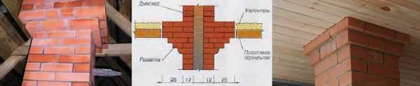
To ensure the tightness of the junction of the pipe to the metal tile, an inner and outer apron is equipped on the roof slope. Installation begins with the inner apron by installing the lower and upper strips, as well as the side elements. The bottom bar is applied to the walls and a line is drawn with a pencil. All other elements are also used as templates for marking other lines. Having measured the line around the entire perimeter of the pipe, it is necessary to make strobes. Perform them with a grinder with a depth of at least 15 mm. After that, they are washed with water from brick dust and allowed to dry well.
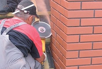 It is unacceptable for the strobe to pass through the place of the brick laying seam. The correct passage of the strobe must be carried out on the surface of the brick!
Installation of strips begins with the bottom wall of the chimney, then two side and top strips. The overlap of the planks should be about 150 mm, thus excluding the possibility of leaks. The edges of the additional elements are inserted into the strobe and filled with sealant. The strips are attached to the pipe with roofing screws. A “tie” is installed under the bottom of the apron, which is necessary for water to drain and can be directed to the valley or to the cornice overhang. A rim is made along the edge of the roof with pliers and a hammer.
When the inner apron is completed and the roof cutting of the chimney is completed, the laying of metal sheets around the chimney continues. Next, equip the outer apron, which performs a decorative role. The junction slats of the outer apron are attached in the same order as the slats of the inner apron. The edges of the planks are no longer led into the strobe, but are attached to the walls of the chimney.
Accessories for roof ventilation passage
It is not necessary to initially complete the device with all possible functional additions, but before the installation itself, it is worth calculating the design so that it remains possible to equip the roof with a new option in the future. In particular, the system can be supplemented with valves and deflectors, which will ensure the removal of air flows from the attic and attic spaces. If the end of the shaft is in close contact with other communication systems, then it will not be superfluous to include special seals in the device, which provide sealing of engineering communications exits. Thus, not only ventilation ducts are protected, but also roof penetrations. In a separate order, it is worth considering the protection of the coating itself from possible effects of gases and warm air.
What is a roof ventilation unit
This may be a structure formed by a whole group of elements, although there are almost monolithic installations that perform the function of removing polluted air. Outwardly, such an element looks like a chimney, only in a more compact size. In any case, the basis of the structure is a metal pipe that passes through the entire roof and is fixed in a special glass made of reinforced concrete.Depending on which ventilation ducts the roof outlet unit continues, its dimensions can be from 1 to several millimeters. The same applies to protective coatings. Usually, galvanized steel or stainless steel is used, which can cope with both physical wind loads and moisture.
Installation of connection to a round pipe
Often, instead of a rectangular brick chimney, a round pipe is used. For waterproofing such a pipe, bitumen-based roll waterproofing or modified bitumen foil tape is used. Moreover, the foil will protect the tape itself from overheating, which will significantly extend its service life.
To protect the outlet of the chimney, it is not necessary to install two stages of abutment.
Instead, an apron-cap, or, as it is also called, a roof passage, is put on a round pipe.
Attach it directly to the crate and seal it with a sealant.
When using a roof passage, it is important to consider one nuance. The rubber heated by the pipe will melt
To prevent this from happening, a clamp with a heat-resistant gasket is attached to the chimney at the junction between the pipe and the apron
The rubber heated by the pipe will melt. To prevent this from happening, a clamp with a heat-resistant gasket is attached to the chimney at the junction between the pipe and the apron.
There is a second solution to the problem - to use a roof passage made of heat-resistant rubber.
https://youtube.com/watch?v=QaWAvbYZWzE
Types of marking
Currently, 11 varieties of ventilation units are produced for various types of roofing material. Passage nodes are known for non-standard duct layouts. Marking the design, alphabetic and numeric combinations are used. They characterize the presence of certain elements:
- The designation UE testifies to the name - the passage node;
- The combination of UE 1 and the presence of the number 01-10 means the standard size of units that are not equipped with a valve and a condensate circle.
- The combination of UE 2 and the presence of the number 01-10 means the typical size of units with a valve, but with a missing condensate ring.
- The combination of UE 3 and numbers 11-20 indicates the standard dimensions of units with a valve and a condensate ring.
When choosing the type of node, you should focus on the climatic operating conditions, the installation of the aerator, the design, and the type of roofing material.
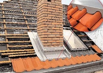
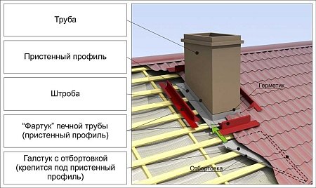
Installation of an adjoining to a rectangular chimney
To prevent leakage at the outlet of the chimney, it is necessary to properly connect. For this, a so-called apron is made. Its main task is to collect and drain water that can get into the gap between the pipe and the corrugated board. As a rule, they make the lower (main) and upper (decorative) junctions.
For the lower connection, you will need a sheet of galvanized steel, and standard strips of the same steel 150 by 230 mm. On such slats there is a 20 mm strobe bend at the top, and a 16 mm bend at the bottom to protect against leakage. The installation procedure is as follows:
Installation of a sheet of galvanized steel from the bottom edge of the chimney to the eaves. A tie may be used instead.
Chimney grating. To do this, the abutment strips are tightly attached to the pipe, with a construction pencil, or a marker, a line is marked along the edge of the bend for the strobe
Gating itself is convenient to produce with a grinder with a circle around the stone.
It is very important to correctly bend the sheets one under the other. Therefore, the first junction bar is installed from below.
Next, the side rails are installed.
The top bar is installed last.
Before installing the profiled sheet, it is necessary to resolve the issue of waterproofing the pipe on the roof from corrugated board. There are two popular ways:
- Using only standard waterproofing film. To do this, when it is installed at the place where the chimney passes, an incision is made with an envelope. After installation, the excess part must be removed, leaving a margin of 5-10 cm, after which the waterproofing can be glued to the pipe. But at the same time there is a risk of moisture getting directly onto the membrane.
- Additional waterproofing. It is best to use self-adhesive waterproofing tape. It is installed under a decorative abutment. The installation sequence is the same as for the lower junction: starting from the bottom, go to the sides, and then up.
The next stage of work is the installation of a profiled sheet, after which decorative junction strips are installed. The order of work here is the same as described above, with the exception of the need for gating.
The node of the passage of air ducts through the roof of corrugated sheet sandwich
Are you sure you were looking for? For the sake of interest, I typed “roof penetrations - pictures”, there is at least this:
Thượng Tá Quân Đội Nhân Dân Việt Nam
As I understand it in question 2 of the question: 1. How to fix the pipe at the level of the sandwich panel 2. How to seal the penetration.
1. The pipe can be fastened with a clamp to the top sheet of the panel, the main fastening is under the roof. 2. Put on a rubber penetration from above. We fasten the base of the penetration with self-tapping screws. Reliable enough. Used many times, no questions asked.
I do not like the knot proposed by the metal profile. The use of bituminous mastics on metal roofing raises many questions. He moves away from the metal. Flows in summer, hardens in winter. Faced with this - the node is constantly flowing.
That is, it turns out from below you need to fence some additional structures.
Given that the base for the gum is not flat and the gum has to repeat all the bends of the roof, it is also doubtful that reliable waterproofing is provided in these places. A curved elastic band will tend to straighten up, and the mastic around the perimeter heated by the sun can “succumb” and release the elastic band up. somehow it looks unreliable. Metalprofile also has such solutions, but they are used at antenna outputs (see attachment).
Well, for now I'm looking towards the penetration option as in the attachment in the pdf file. A glass made of a square tube with a round tube inside. Between themselves, they are connected at the bottom with a sheet - the “bottom” of the glass, at the top with four short corners. Air ducts are connected to the inner pipe through flanges.
Maybe doubtful. But it is used repeatedly and there are no special complaints. In private housing construction, this is generally the case everywhere. But if it is doubtful, then it is doubtful.
According to section 1-1, what is the distance from the ridge? You can put a sheet on top of the corrugation from the ridge to the pipe. Then you can leave the mastic. Some node is laborious. Why such difficulties. What size pipe? What is a pipe? It is unlikely that there will be two runs side by side as they are drawn.
For the project, you can leave such a node. But in reality, no one will do it. Because complex and non-technological. I'll explain why: 1. You need to place the runs next to the pipe. To do this, you need to issue a task to the designers. 2. First, the roof will be assembled from panels, the holes will then be cut out. With the specified node, you must first install a steel multi-layer penetration, and then put a panel on it. 3. It is impossible to make normal square-section flashings in plan. There will be no flashings on the tops. 4. There will be freezing on the metal, do not insulate inside. 5. On the “steel multilayer penetration”, you need to develop KM, then KMD .. 6. There will be a gap between the pipe and the panel. Not as pretty and straight as pictured.
The node of the passage of air ducts through the roof of the profiled sheet Node of passage of air ducts through the roof from profiled sheet/sandwich Structures of buildings and structures
Appointment of the roofing element UP

Scheme and overall dimensions of the passage unit for a soft roof.
The node for the passage of the ventilation duct through the roof is marked with UE, it has 11 items in the standard version. For difficult operating conditions, this additional element is designed and manufactured individually. The node for the passage of the pipe through the roof is regulated by GOST 15150, which determines the diameter and dimensions of the structure.
With the help of roof penetrations, only cold air is removed; structures made of refractory materials are used for chimneys, the dimensions of which are controlled by other SNiP standards.
When choosing a UE for an air duct through the roof, they are guided by the degree of dustiness, temperature difference, gas contamination, humidity of the transported air mixture. Fixing the additional element of the passage of the air duct through the roof is carried out to the load-bearing frame of the roof (batten or counter-lattice). Shown in Fig.1.
Chimney lining with corrugated board
Chimneys are subject to aggressive environmental influences. This:
- Temperature fluctuations and precipitation.
- The formation of condensate due to the temperature difference between the air and the chimney.
Also, a bare pipe on a corrugated roof is not attractive from a purely aesthetic point of view. To solve both of these problems, it is necessary to carry out the lining of the chimney.
There are several popular types of facing materials:
- Tiles and clinker bricks.
- Plaster.
- Decking.
We will consider how to line the pipe on the roof with corrugated board. The profile sheet has several advantages at once:
- Durability
- Wide range of colors
- Ease of installation
- Easy Maintenance
- light weight
- Temperature resistance
- Ecological cleanliness
In addition, corrugated board manufacturers produce special facing sheets designed for finishing various structures, including chimneys.
Thus, for lining the pipe we need:
- Gloves or mittens to protect hands. Profiled sheets are very sharp at the edges, especially if self-cutting was carried out.
- Electric jigsaw with a special blade. In extreme cases, in its absence, you can use a grinder with a thin circle. But keep in mind that the grinder heats the metal very much, which harms the polymer and zinc coating of the sheet.
- Screwdriver and screws.
- Insulation. Any non-flammable material will do.
- Dowels "mushrooms" for fixing insulation and ordinary dowels for attaching the frame.
- Hammer for fixing dowels.
- Drill with a drill for dowels. In its absence, you can use a screwdriver, but this will slightly increase the time costs.
- Metal profile to create a frame. In its absence, wooden bars treated with an antiseptic are suitable.
- Directly facing elements: profiled sheet and additional elements.
We proceed directly to the installation.
- The first stage of work is the installation of insulation. To do this, we drill a hole right through it with a drill in the chimney and fix them with a hammer.
- Next, we build a frame for cladding from a metal profile and wooden bars. We fasten it to the chimney as well as a heater.
- We measure and cut profiled sheets. The main principle: "Measure seven times - cut once."
- Attaching the cladding to the frame. To each other, the sheets can adjoin end-to-end or overlap. The second option is preferable, as it guarantees the absence of gaps.
- Installation of additional elements made to order. This is the top eaves bar and chimney umbrella.
- For greater aesthetic beauty, you can perform work on the installation of a decorative junction of the chimney.
Thus, today we found out how to bring the pipe through the roof from corrugated board, as well as how to line the chimney with corrugated board.
Parameter table
vendor code
d1, mm
d2, mm
B, mm
A, mm
H, mm
Weight, kg
K2.MU.UPK45.080
80
90
380
520
200
2
K2.MU.UPK45.100
100
110
400
530
200
2,10
K2.MU.UPK45.110
110
120
410
540
200
2,20
K2.MU.UPK45.115
115
125
415
540
200
2,20
K2.MU.UPK45.120
120
130
420
560
200
2,30
K2.MU.UPK45.130
130
140
430
570
200
2,35
K2.MU.UPK45.140
140
150
440
580
200
2,40
K2.MU.UPK45.150
150
160
450
590
200
2,50
K2.MU.UPK45.160
160
170
460
610
200
2,50
K2.MU.UPK45.180
180
190
480
640
200
2,70
K2.MU.UPK45.200
200
210
500
660
200
2,90
K2.MU.UPK45.210
210
220
510
680
200
2,90
K2.MU.UPK45.220
220
230
520
690
200
2,90
K2.MU.UPK45.230
230
240
530
700
200
3
K2.MU.UPK45.240
240
250
540
710
200
3,10
K2.MU.UPK45.250
250
260
550
730
200
3,10
K2.MU.UPK45.260
260
270
560
750
200
3,50
K2.MU.UPK45.280
280
290
580
870
200
4,10
K2.MU.UPK45.300
300
310
600
800
200
4,50
K2.MU.UPK45.320
320
330
620
850
200
4,90
K2.MU.UPK45.350
350
360
650
870
200
5,40
K2.MU.UPK45.400
400
41
700
940
200
5,80
K2.MU.UPK45.450
450
460
750
1010
200
6,30
K2.MU.UPK45.500
500
510
800
1080
200
6,70
K2.MU.UPK45.550
550
560
850
1150
200
7,30
K2.MU.UPK45.600
600
610
900
1220
200
7,80
K2.MU.UPK45.650
650
660
950
1290
200
7,80
K2.MU.UPK45.700
700
710
1000
1360
200
7,90
K2.MU.UPK45.750
750
760
1050
1420
200
8,10
K2.MU.UPK45.800
800
810
1100
1490
200
8,10
K2.MU.UPK45.850
850
860
1150
1630
200
8,70
K2.MU.UPK45.900
900
910
1200
1640
200
9,70
K2.MU.UPK45.1000
1000
1010
1300
1770
200
10,70
K2.MU.UPK45.1100
1100
1110
1400
1980
200
11,20
vendor code
K2.MU.UPK45.080
- K2.MU.UPK45.080
- K2.MU.UPK45.100
- K2.MU.UPK45.110
- K2.MU.UPK45.115
- K2.MU.UPK45.120
- K2.MU.UPK45.130
- K2.MU.UPK45.140
- K2.MU.UPK45.150
- K2.MU.UPK45.160
- K2.MU.UPK45.180
- K2.MU.UPK45.200
- K2.MU.UPK45.210
- K2.MU.UPK45.220
- K2.MU.UPK45.230
- K2.MU.UPK45.240
- K2.MU.UPK45.250
- K2.MU.UPK45.260
- K2.MU.UPK45.280
- K2.MU.UPK45.300
- K2.MU.UPK45.320
- K2.MU.UPK45.350
- K2.MU.UPK45.400
- K2.MU.UPK45.450
- K2.MU.UPK45.500
- K2.MU.UPK45.550
- K2.MU.UPK45.600
- K2.MU.UPK45.650
- K2.MU.UPK45.700
- K2.MU.UPK45.750
- K2.MU.UPK45.800
- K2.MU.UPK45.850
- K2.MU.UPK45.900
- K2.MU.UPK45.1000
- K2.MU.UPK45.1100
-
d1, mm
80 -
d2, mm
90 -
B, mm
380 -
A, mm
520 -
H, mm
200 -
Weight, kg
2
-
d1, mm
100 -
d2, mm
110 -
B, mm
400 -
A, mm
530 -
H, mm
200 -
Weight, kg
2,10
-
d1, mm
110 -
d2, mm
120 -
B, mm
410 -
A, mm
540 -
H, mm
200 -
Weight, kg
2,20
-
d1, mm
115 -
d2, mm
125 -
B, mm
415 -
A, mm
540 -
H, mm
200 -
Weight, kg
2,20
-
d1, mm
120 -
d2, mm
130 -
B, mm
420 -
A, mm
560 -
H, mm
200 -
Weight, kg
2,30
-
d1, mm
130 -
d2, mm
140 -
B, mm
430 -
A, mm
570 -
H, mm
200 -
Weight, kg
2,35
-
d1, mm
140 -
d2, mm
150 -
B, mm
440 -
A, mm
580 -
H, mm
200 -
Weight, kg
2,40
-
d1, mm
150 -
d2, mm
160 -
B, mm
450 -
A, mm
590 -
H, mm
200 -
Weight, kg
2,50
-
d1, mm
160 -
d2, mm
170 -
B, mm
460 -
A, mm
610 -
H, mm
200 -
Weight, kg
2,50
-
d1, mm
180 -
d2, mm
190 -
B, mm
480 -
A, mm
640 -
H, mm
200 -
Weight, kg
2,70
-
d1, mm
200 -
d2, mm
210 -
B, mm
500 -
A, mm
660 -
H, mm
200 -
Weight, kg
2,90
-
d1, mm
210 -
d2, mm
220 -
B, mm
510 -
A, mm
680 -
H, mm
200 -
Weight, kg
2,90
-
d1, mm
220 -
d2, mm
230 -
B, mm
520 -
A, mm
690 -
H, mm
200 -
Weight, kg
2,90
-
d1, mm
230 -
d2, mm
240 -
B, mm
530 -
A, mm
700 -
H, mm
200 -
Weight, kg
3
-
d1, mm
240 -
d2, mm
250 -
B, mm
540 -
A, mm
710 -
H, mm
200 -
Weight, kg
3,10
-
d1, mm
250 -
d2, mm
260 -
B, mm
550 -
A, mm
730 -
H, mm
200 -
Weight, kg
3,10
-
d1, mm
260 -
d2, mm
270 -
B, mm
560 -
A, mm
750 -
H, mm
200 -
Weight, kg
3,50
-
d1, mm
280 -
d2, mm
290 -
B, mm
580 -
A, mm
870 -
H, mm
200 -
Weight, kg
4,10
-
d1, mm
300 -
d2, mm
310 -
B, mm
600 -
A, mm
800 -
H, mm
200 -
Weight, kg
4,50
-
d1, mm
320 -
d2, mm
330 -
B, mm
620 -
A, mm
850 -
H, mm
200 -
Weight, kg
4,90
-
d1, mm
350 -
d2, mm
360 -
B, mm
650 -
A, mm
870 -
H, mm
200 -
Weight, kg
5,40
-
d1, mm
400 -
d2, mm
41 -
B, mm
700 -
A, mm
940 -
H, mm
200 -
Weight, kg
5,80
-
d1, mm
450 -
d2, mm
460 -
B, mm
750 -
A, mm
1010 -
H, mm
200 -
Weight, kg
6,30
-
d1, mm
500 -
d2, mm
510 -
B, mm
800 -
A, mm
1080 -
H, mm
200 -
Weight, kg
6,70
-
d1, mm
550 -
d2, mm
560 -
B, mm
850 -
A, mm
1150 -
H, mm
200 -
Weight, kg
7,30
-
d1, mm
600 -
d2, mm
610 -
B, mm
900 -
A, mm
1220 -
H, mm
200 -
Weight, kg
7,80
-
d1, mm
650 -
d2, mm
660 -
B, mm
950 -
A, mm
1290 -
H, mm
200 -
Weight, kg
7,80
-
d1, mm
700 -
d2, mm
710 -
B, mm
1000 -
A, mm
1360 -
H, mm
200 -
Weight, kg
7,90
-
d1, mm
750 -
d2, mm
760 -
B, mm
1050 -
A, mm
1420 -
H, mm
200 -
Weight, kg
8,10
-
d1, mm
800 -
d2, mm
810 -
B, mm
1100 -
A, mm
1490 -
H, mm
200 -
Weight, kg
8,10
-
d1, mm
850 -
d2, mm
860 -
B, mm
1150 -
A, mm
1630 -
H, mm
200 -
Weight, kg
8,70
-
d1, mm
900 -
d2, mm
910 -
B, mm
1200 -
A, mm
1640 -
H, mm
200 -
Weight, kg
9,70
-
d1, mm
1000 -
d2, mm
1010 -
B, mm
1300 -
A, mm
1770 -
H, mm
200 -
Weight, kg
10,70
-
d1, mm
1100 -
d2, mm
1110 -
B, mm
1400 -
A, mm
1980 -
H, mm
200 -
Weight, kg
11,20
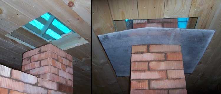
Passage through the ceiling of a brick chimney
Brick itself is a good heat insulator, however, for a brick oven, compliance with the rules for passing through combustible materials is also required: there must be a distance of at least 25 cm from the edge of the chimney channel to this material. To ensure this, stove-makers make a special penetration on the pipe (see figure) by increasing the wall thickness of the brick chimney at the point of passage through the ceiling.
Roof passage brick chimney
If for some reason it is impossible to make such a penetration, you can cut a hole in the ceiling that will be 10 centimeters larger than the size of the chimney on each side. And then repeat the penetration of the round furnace through the ceiling:
- close the edges with heat-resistant heat-insulating material;
- close it with strips of metal (minerite is also suitable if someone has it);
- sew up with a metal sheet from the side of the room;
- fill the formed voids from the side of the attic / second floor with heat-resistant heat-insulating material;
- close, if necessary, the ceiling cutting from the side of the attic / second floor with a sheet of metal.
With this option, the brick pipe is sufficiently reliably insulated (only use heat-resistant heat-insulating materials with a use temperature of 800-1000 ° C).
It is possible to bring a brick pipe through the ceiling without special penetration
Ventilation passage through the roof types, installation
 Reasonably adjusted ventilation units in the places of passage through the roof will provide the roof with additional reliability and extend the service life. Due to the many positive functions, the air circulation system in the house is not just an important element, but a vital one.
Warm air is generated in living quarters for a variety of reasons. By its nature, it rises up through coverings, into higher rooms or outdoors. Most of the warm air is formed, of course, during the heating season.
Therefore, it is very important to properly adjust the system and ventilation units, in particular, so that the air circulates in the house, and only recycled air comes out.
The exit path of ventilation to the roof and passage through the roof is carried out from exhaust and other air circulation channels in the building.
Roof ventilation units
The forced exit of recycled air from the building is a key task of the roof outlet of recycled air. The correct installation of this system must be carried out in accordance with GOST-15150. It contains data on the distance of the ventilation passage to the edge of the slab and the standard parameters of openings in floor slabs. Passage nodes are also suitable for the removal of chimneys, which are used for buildings with wood-burning hearths - a fireplace, stove, etc.
Roof ventilation depends on the exhaust ducts and the type of roof. It is divided into several types of forms:
Ventilation passage nodes are openings in the roof slab. They are equipped with aluminum ventilation pipes, designed specifically for placement on the roof. Experts recommend using aluminum pipes 1 mm thick. But the sizes of ventilation are different, but choosing an individual option is not difficult.
Ventilation systems with metal pipes are:
To select the correct nodes for the passage through the roof, the following characteristics are taken into account:
- humidity level;
- volumes of gas emissions;
- boundaries of air temperature fluctuations;
- degree of accumulation and formation of dust.
During the installation work, it is necessary to take into account some of the nuances:
- roof pitch;
- the distance between the ridge and the penetration;
- materials from which the roof is created;
- the area of the room directly under the roof.
On reinforced concrete material, the nodes of the passage through the roof are fastened with anchor bolts. The bolts themselves are placed in "glasses" during the installation process. It is also necessary to use plates with holes, which are designed specifically for the passage of ventilation through the roof. If the width of the opening does not correspond to a solid ribbed or hollow slab, places made of monolithic concrete are equipped in the passage zones.
If ventilation is carried out through a roof with a metal crate, the installation process is similar, but metal "glasses" are used.
A large building with a considerable number of residential, industrial or warehouse premises requires ventilation ducts to be provided even during the planning period of the building.
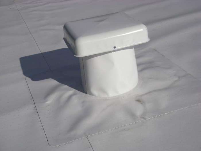
The sequence of actions for mounting the node through the roof
- The series and model of the special seal ring is selected.
- The soft part is pulled onto the pipe.
- The base is shaped according to the surface of the roof. For corrugated board, it is most difficult to adapt the base due to its ribbed surface.
- Sealant is applied under the flange for waterproofing.
- The flange is attached to the base with screws.
About ventilation ducts
- without valves;
- with valves;
- with thermal insulation;
- without thermal insulation;
- with a controller that monitors the position of the valves.
Systems with a manual type of adjustment are used in cases where the system does not need constant monitoring of operating modes. This ventilation system control method consists of:
An electric single-turn mechanism controls the operation of the valve - closes and opens it. The valve itself is made of stainless steel with a thickness of 0.8 mm.
The nodes through the soft roof are mounted on a base of galvanized steel, which is installed together with a layer of thermal insulation. Warm material should be no thinner than 5 cm, mineral wool is best suited for this. Later it will be possible to place special deflectors in the heat insulator - an aerodynamic device that is attached to the top of the ventilation or chimney pipe. Designed to disperse the flow of outgoing recycled air. At the end of the installation of the ventilation blades, plastic tubes made of plastic are carried inside, through which the electrical wiring passes.
A properly equipped unit will function for a long time and even muffle extraneous noise from the outside.
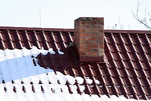
Recommended chimney location
The exit point of the chimney through the metal tile is determined at the initial stage of its design.It is not recommended to install a chimney through valleys due to the lack of a guarantee of complete tightness at the junction with the roof. In addition, the greatest amount of snow is collected in the valleys, which can exert a large load on the junctions of the pipe with the roof and violate the integrity of the entire structure assembly.
It is also irrational when the pipe on the roof of metal tiles is laid near the windows of the attic rooms. Carbon monoxide or smoke can be blown into the room by a slight gust of wind.
The optimal location of the chimney is to install it near the ridge. In winter, the least accumulation of snow occurs in this place, which means that the possibility of leakage is minimized. The pipe near the ridge has the smallest height, which favorably affects the possible impact of atmospheric phenomena. In the cold season, the least condensate formation occurs here, since the main part of the pipe is not located in the cold zone.
This option also has some disadvantages. The rafter system does not provide for the installation of a ridge beam, or the beam is made with a gap, which affects the strength of the entire structure. You have to install additional support nodes under the rafters, which is not always beneficial if you plan to use the attic as an attic room. Therefore, a rational solution would be to pass the chimney near the ridge run.
For flat roofs, a chimney height of 500 mm is sufficient. In the case of a ridge roof, the chimney is laid through the metal tile to a height that depends on the distance to the ridge :
- at a distance of up to 1.5 meters, the height of the chimney must be at least 500 mm above the ridge;
- if the distance to the ridge is within 1.5-3 meters, the pipe should be flush with the ridge;
- in the case when the distance exceeds 3 meters, the height of the chimney is determined by a line passing at an angle of 10 degrees from the ridge run to the horizon.