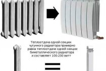
Heating and ventilation system VAZ 2108 2115
Heater air ducts and control parts VAZ 2108 - 2115
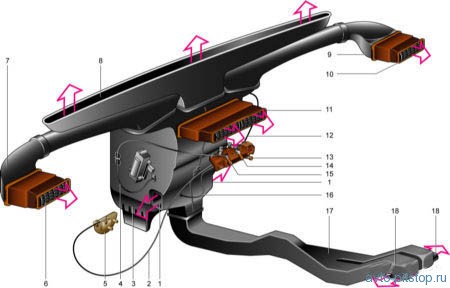
1 - a window for supplying air to the legs of the driver and passenger;
2 - crane control rod;
3 - heater casing;
4 – draft of the damper of heating of legs;
5 - heater valve;
6, 10 - side nozzle;
7, 9 - air duct of the side nozzle;
8 – an air duct of heating of a windshield;
11 – central nozzle;
12 – draft of the damper of heating of glass;
13 - control handle for the valve and heater damper;
14 – the handle of management of a damper of heating of a windshield;
15 – handle for controlling the damper for heating the legs;
16 - thrust of the heater control damper;
17 - air duct for internal ventilation;
18 - windows for heating the legs of the rear passengers.
Scheme of operation of the heater VAZ 2108 - 2115
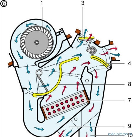
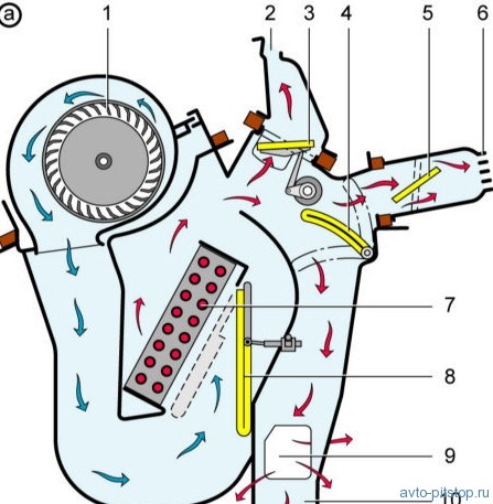
a - VAZ-2108;
b - VAZ-2108-01;
1 – fan impeller;
2 – an air duct of heating of a windshield;
3 – a damper of heating of a windshield;
4 - damper for heating the legs;
5 - damper of the central nozzle;
6 - central nozzle;
7 - radiator;
8 – heater control damper;
9 - a window for heating the driver's legs;
10 - air duct for internal ventilation.
Description of the design of the heating and ventilation system VAZ 2108 - 2115
Air can enter the cabin through the upper slots on the instrument panel, side and central air duct nozzles, holes in the heater casing (to the feet), as well as through the lowered door windows. An electric fan is used to increase the air supply.
Since August 1998, the Samar part has been equipped with a heater 2108-01. The heater 2108-01 is distinguished by an almost horizontal arrangement of the radiator and a different distribution of air flows: in the intermediate positions of the damper, hot air enters from below, thanks to which cooler air is supplied to the windows, and warmer air is supplied to the legs. The fan motor is collector, DC, with excitation from permanent magnets. The fan speed is controlled by a four-position switch on the instrument panel. Depending on the selected speed, the electric motor is connected to the car's on-board network directly or through an additional resistor. The latter has two spirals with a resistance of 0.23 ohms and 0.82 ohms. If both spirals are included in the circuit, the fan rotates at low speed, if only one (0.23 Ohm) is at medium, directly connected, the fan rotates at maximum speed. The frequency of rotation of the motor shaft with an impeller at a voltage of 12 V and an air temperature of (25 ± 10) ° C is 4100 ± 200 min–1. Consumed current at maximum speed - no more than 14 A.
It is not recommended to press the fan wheel off the motor shaft, because can upset its balance. The electric motor cannot be repaired (with the exception of stripping the collector), if it fails, it should be replaced as an assembly with the fan wheel.
A heater uses the heat of the engine coolant to heat the air. The heater radiator is installed in the heater casing and consists of two plastic tanks and two rows of aluminum tubes with pressed plates (the baffle is in the right tank). The flow of liquid through the radiator (independent of the thermostat) is created by the engine coolant pump and controlled by a valve attached to the bulkhead. The heater is controlled by two handles for the distribution of air flows and a handle for controlling the valve and the heater damper.