1. EQUATIONS OF DIRECT AND INVERSE HEAT BALANCE
The most complete picture of the economic performance of a ship's boiler is given by the heat balance, which shows how much heat enters the boiler, what part of it is used usefully (for steam production), and what part is lost.
Heat balance is the application of the law of conservation of energy to the analysis of the working process of a boiler. When analyzing the working process of the boiler in the stationary (or steady) mode of its operation, the heat balance is compiled on the basis of the results of thermal tests. V
|
In general terms, the heat balance equation has the form |
|
|
i=n |
|
|
QLOW = Q1 + ∑QLOT ,i |
(4,1) |
|
i=2 |
where QPOD is the amount of heat supplied to the steam boiler, kJ/kg; Q1 – useful heat, kJ/kg;
QPOT – heat losses, kJ/kg
In the standard calculation method developed for stationary boilers, it is recommended to take into account all the heat supplied to the furnace from 1 kg of fuel (Fig. 4.1), i.e.
|
Q |
UNDER |
= Q |
P |
=QP+Q+Q |
B |
+Q |
ETC |
(4,2) |
|
H T |
where QHP is the net calorific value of the working mass of fuel, kJ/kg;
QT, QB, QPR - the amount of heat introduced, respectively, with fuel, air and steam, which is supplied for fuel atomization, kLJ/kg.
The last three values are determined as follows. Physical heat of fuel
|
QT |
= cT tT |
(4,3) |
where cT is the heat capacity of the fuel at its heating temperature tT, kJ/(kg K)
The value of QB takes into account only the heat that is received by the air outside the boiler, for example, in a steam air heater. With the usual layout of the boiler with gas air heating, it is equal to the amount of heat introduced into the furnace with cold air, i.e.
|
QB = QXB =αV ocXBtXB =αI ХВ |
(4,4) |
||
|
where α is the coefficient of excess air; |
|||
|
сХВ is the heat capacity of cold air at a temperature tXB; |
|||
|
I XB- enthalpy of the theoretical amount of air V, kJ / kg |
|||
|
The amount of heat supplied to the furnace with steam for spraying fuel oil, |
|||
|
QPR = |
GPR |
(iPR −i") |
(4,5) |
|
BK |
where GPR is the steam consumption for atomizing the VC fuel, kg/h;
iPR, i” – steam enthalpy for atomization of fuel and dry saturated steam in flue gases, kJ/kg.
The value of i” in equation (4.5) can be taken equal to 2500 kJ/kg, which corresponds to a partial pressure of water vapor in the flue gases pH2O of 0.01 MPa.
For marine boilers, the defining quantity in equation (4.2) is QHP, since the sum of the remaining terms does not exceed 1% of QP. In this regard, when compiling the heat balance of marine boilers, it is usually taken when the air is heated by flue gases QPOD \u003d QHP, and when
heated with steam QPOD = QHP +QB . In this case, the first equation is the main one, since the steam
Types of heat waste
Each site has its own type of heat consumption. Let's consider each of them in more detail.
Boiler room
A boiler is installed in it, which converts the fuel and transfers thermal energy to the coolant. Any unit loses part of the generated energy due to insufficient combustion of fuel, heat output through the boiler walls, problems with blowing. On average, the boilers used today have an efficiency of 70-75%, while newer boilers will provide an efficiency of 85% and their percentage of losses is much lower.
An additional impact on energy waste is exerted by:
- lack of timely adjustment of boiler modes (losses increase by 5-10%);
- discrepancy between the diameter of the burner nozzles and the load of the thermal unit: heat transfer is reduced, the fuel does not burn completely, losses increase by an average of 5%;
- insufficiently frequent cleaning of the boiler walls - scale and deposits appear, work efficiency decreases by 5%;
- lack of monitoring and adjustment means - steam meters, electricity meters, heat load sensors - or their incorrect setting reduces the utility factor by 3-5%;
- cracks and damage to the boiler walls reduce efficiency by 5-10%;
- the use of outdated pumping equipment reduces the costs of the boiler house for repair and maintenance.
Losses in pipelines
The efficiency of the heating main is determined by the following indicators:
- Efficiency of pumps, with the help of which the coolant moves through the pipes;
- quality and method of laying the heat pipe;
- correct settings of the heating network, on which the distribution of heat depends;
- pipeline length.
With proper design of the thermal route, the standard losses of thermal energy in thermal networks will not exceed 7%, even if the energy consumer is located at a distance of 2 km from the place of fuel production. In fact, today in this section of the network, heat losses can reach 30 percent or more.
Losses of objects of consumption
It is possible to determine the excess energy consumption in a heated room if there is a meter or meter.
The reasons for this kind of loss can be:
- uneven distribution of heating throughout the room;
- the level of heating does not correspond to weather conditions and the season;
- lack of recirculation of hot water supply;
- lack of temperature control sensors on hot water boilers;
- dirty pipes or internal leaks.
Calculation of the thermal balance of the boiler. Determination of fuel consumption
Boiler thermal balance
Drawing up the heat balance of the boiler consists in establishing equality between the amount of heat entering the boiler, called the available heat QP, and the amount of useful heat Q1 and heat losses Q2, Q3, Q4. Based on the heat balance, the efficiency and the required fuel consumption are calculated.
The heat balance is compiled in relation to the steady state thermal state of the boiler per 1 kg (1 m3) of fuel at a temperature of 0°C and a pressure of 101.3 kPa.
The general heat balance equation has the form:
QP + Qin.in = Q1 + Q2 + Q3 + Q4 + Q5 + Q6, kJ/m3, (2.4.1-1)
where QP — available heat of the fuel; Qv.vn - heat introduced into the furnace by air when it is heated outside the boiler; Qf - heat introduced into the furnace by steam blast ("nozzle" steam); Q1 - useful heat; Q2 — loss of heat with flue gases; Q3 - heat loss from chemical incompleteness of fuel combustion; - heat loss from mechanical incompleteness of fuel combustion; Q5 — heat loss from external cooling; Q6 — heat loss of slag.
When burning gaseous fuel in the absence of external air heating and steam blast, the values of Qv.vn, Qf, Q4, Q6 are equal to 0, so the heat balance equation will look like this:
QP = Q1 +Q2 +Q3 +Q5, kJ/m3. (2.4.1-2)
Available heat of 1 m3 of gaseous fuel:
QP = Qdi + itl, kJ/m3, (2.4.1-3)
where Qdi — net calorific value of gaseous fuel, kJ/m3 (see Table 1); itl — physical heat of fuel, kJ/m3. It is taken into account when the fuel is heated by an external heat source. In our case, this does not happen, so QP = Qdi, kJ/m3, (2.4.1-4)
QP = 36 800 kJ/m3. (2.4.1-5)
Heat loss and boiler efficiency
Heat loss is usually expressed as a % of the available heat of the fuel:
etc. (2.4.2-1)
Heat loss with flue gases into the atmosphere is defined as the difference between the enthalpies of combustion products at the outlet of the last heating surface (economizer) and cold air:
, (2.4.2-2)
where Iwow = IN EC is the enthalpy of the outgoing gases. Determined by interpolation according to table 7 for a given flue gas temperature twow°С:
, kJ/m3. (2.4.2-3)
bwow = bNEC — coefficient of excess air behind the economizer (see Table 3);
I0.h.v. is the enthalpy of cold air,
I0.x.v = (ct)v*VH = 39.8*VH, kJ/m3, (2.4.2-4)
where (ct)v \u003d 39.8 kJ / m3 - enthalpy of 1 m3 of cold air at th.v. = 30°С; VH is the theoretical air volume, m3/m3 (see Table 4) = 9.74 m3/m3.
I0.x.v = (ct)v*VH = 39.8*9.74 = 387.652 kJ/m3, (2.4.2-5)
According to the table of parameters of steam boilers twow = 162°С,
,(2.4.2-6)
(2.4.2-7)
Heat loss from chemical incomplete combustion q3 , %, is due to the total heat of combustion of products of incomplete combustion remaining in the flue gases (CO, H2, CH4 and etc.). For the designed boiler, we accept
q3 = 0,5%.
Heat loss from outdoor cooling q5 , %, taken according to table 8, depending on the steam output of the boiler D, kg/s,
kg/s, (2.4.2-8)
where D, t/h - from the initial data = 6.73 t/h.
Table 8 - Heat losses from external cooling of a tail-surface steam boiler
|
Rated steam output of the boiler D, kg/s (t/h) |
Heat loss q5 , % |
|
1,67 (6) |
2,4 |
|
2,78 (10) |
1,7 |
|
4,16 (15) |
1,5 |
|
5,55 (20) |
1,3 |
|
6,94 (25) |
1,25 |
Finding the approximate value of q5 , %, for a nominal steam capacity of 6.73 t/h.
(2.4.2-9)
Total heat loss in the boiler:
Yq = q2 + q3 + q5 = 4,62 + 0,5 + 1,93 = 7,05 % (2.4.2-10)
Boiler efficiency (gross):
hTO \u003d 100 - Yq \u003d 100 - 7.05 \u003d 92.95%. (2.4.2-11)
Measures to reduce heat loss from the surface of pipelines
Energy saving during the transportation of thermal energy primarily depends on the quality of thermal insulation. The main energy-saving measures that reduce heat loss from the surface of pipelines are:
isolation of uninsulated areas and restoration of the integrity of existing thermal insulation;
restoration of the integrity of the existing waterproofing;
applying coatings consisting of new heat-insulating materials, or using pipelines with new types of heat-insulating coatings;
insulation of flanges and valves.
Insulation of uninsulated sections is a primary energy saving measure, since heat losses from the surface of uninsulated pipelines are very large compared to losses from the surface of insulated pipelines, and the cost of applying thermal insulation is relatively low.
New types of heat-insulating coatings should have not only low thermal conductivity, but also low air and water permeability, as well as low electrical conductivity, which reduces electrochemical corrosion of the pipe material.
In case of violation of the integrity of the layer of waterproofing coatings, an increase in the moisture content of the thermal insulation occurs. Since the thermal conductivity of water in the temperature range of the heating network X= 0.6 - 0.7 W / (m • K), and the thermal conductivity of thermal insulation materials is usually A,from \u003d 0.035 -4-0.05 W / (m • K), then wetting the material can increase its thermal conductivity several times (in practice, more than 3 times).
Moistening of thermal insulation contributes to the destruction of pipes due to corrosion of their outer surface, as a result of which the service life of pipelines is reduced several times. Therefore, an anti-corrosion coating is applied to the metal surface of the pipe, for example, in the form of silicate enamels, isol, etc.
At present, heat pipelines of the "pipe in pipe" type with polyurethane foam insulation in a waterproof shell with remote control of the integrity of the insulation are being widely introduced. This design provides for pre-insulation with polyurethane foam and enclosing in polyethylene not only pipes, but also all system components (ball fittings, temperature compensators, etc.). Heat pipelines of this design are laid underground without channels and provide significant energy savings due to the prefabrication of individual insulated elements at the factory and high heat and moisture impermeability. Successful operation of pre-insulated pipelines requires high quality installation. At the same time, they can function without replacement for up to 30 years.
Preventive measures to reduce heat loss from the surface of pipelines are: prevention of flooding of pipelines as a result of installing drains (if they are not available) and keeping them in proper order; ventilation of passage and non-passage channels to prevent condensate from entering the surface of the thermal insulation.
Another measure that reduces heat loss from the surface of pipelines is the transition of the heat supply system to a lower temperature graph (from 150/70 to 115/70 or 95/70 °C / °C), which leads to a decrease in the temperature difference of the heat carrier in the supply pipeline and environment. However, this will require a greater flow of coolant through the system in order to transfer the required amount of heat to the consumer. To do this, you need to increase the cost of electricity to drive the pumps.Therefore, to determine the feasibility of carrying out the event under consideration, a feasibility study is necessary.
Thermal calculation of the combustion chamber
Using the design data of the boiler, we will draw up a calculation scheme for the furnace.
Rice. 2.1 - Scheme of the combustion chamber
We present the calculation of the furnace in table 2.3.
Table 2.3
|
Calculated value |
Designation |
Dimension |
Formula or justification |
Payment |
|
Diameter and thickness of screen pipes |
dx |
mm |
According to the drawing |
32x6 |
|
Pipe pitch |
S1 |
mm |
Also |
46 |
|
Surfaces: |
||||
|
front wall |
Ff |
m2 |
According to fig. 2.1 |
33,3.16,32=543,5 |
|
back wall |
Fz |
Also |
||
|
side wall |
Fb |
|||
|
hearth |
Funder |
8,47.16,32=138,2 |
||
|
ceiling |
Fp |
3,2.16,32=52,2 |
||
|
exit window |
Fout |
(9+2,8+1,34).16,32=214,4 |
||
|
The total surface of the walls of the combustion chamber |
Fst |
Ff+Fc+2Fb+Fsub+Fp+ +Fout |
543,5+442,9+2.233,5+138,2+52,2+214,4=1860 |
|
|
The volume of the combustion chamber |
Vt |
m3 |
According to fig. 2.1 |
233,5.16,32=3811 |
|
Effective thickness of the radiating layer |
s |
m |
||
|
Thermal stress of the furnace volume |
kW/m3 |
|||
|
The coefficient of excess air in the furnace |
T |
— |
Accepted earlier |
1,05 |
|
hot air temperature |
tg.c. |
WITH |
Given |
333 |
|
Hot air enthalpy |
kJ/m3 |
According to the table 2.2 |
4271,6 |
|
|
The heat introduced by the air into the furnace |
Qv |
kJ/m3 |
||
|
Useful heat dissipation in the furnace |
QT |
kJ/m3 |
||
|
Theoretical combustion temperature |
a |
WITH |
According to the table 2.2 |
2145C |
|
Absolute theoretical combustion temperature |
Ta |
TO |
a+273 |
2418 |
|
Burner height |
hg |
m |
According to fig. 2.1 |
|
|
Firebox height (up to the middle of the outlet gas window) |
Nt |
m |
Also |
|
|
Temperature maximum shift above the burner zone |
X |
— |
When using vortex burners in several tiers and D> 110kg/s |
0,05 |
|
Relative position of the temperature maximum along the furnace height |
xt |
— |
||
|
Coefficient |
M |
— |
||
|
The temperature of the gases at the outlet of the furnace |
WITH |
We accept in advance |
1350 |
|
|
Absolute gas temperature at the furnace outlet |
TO |
1623 |
||
|
Enthalpy of gas |
kJ/m3 |
According to the table 2.2 |
23993 |
|
|
Average total heat capacity of combustion products |
Vcav |
kJ/(m3.K) |
||
|
The pressure in the furnace |
R |
MPa |
accept |
0,1 |
|
Coefficient of attenuation of rays by triatomic gases |
||||
|
Thermal emissivity of non-luminous gases |
G |
— |
||
|
The ratio between the content of carbon and hydrogen in the fuel |
— |
|||
|
Coefficient of beam attenuation by soot particles |
||||
|
Coefficient of attenuation of rays by a luminous torch |
k |
|||
|
The coefficient of thermal radiation of the luminous part of the torch |
With |
— |
||
|
Coefficient characterizing the proportion of the furnace volume filled with the luminous part of the torch |
m |
— |
When burning gas and |
0,1 |
|
Torch thermal radiation coefficient |
f |
— |
||
|
Screen angle |
X |
— |
For fin screens |
1 |
|
Conditional coefficient of surface contamination |
— |
When burning gas and wall membrane screens |
0,65 |
|
|
Shield Thermal Efficiency Ratio |
eq |
— |
.X |
0,65 |
|
Temperature coefficient |
A |
— |
For natural gas |
700 |
|
Correction factor for mutual heat exchange of gas volumes of the upper part of the furnace and screens |
— |
|||
|
Conditional coefficient of pollution of the surface of the entrance to the screen |
exit |
— |
0,65.0,52=0,338 |
|
|
Coefficient of thermal efficiency of the output surface |
exit |
— |
out.x |
0,338 |
|
Average thermal efficiency coefficient |
Wed |
— |
||
|
Furnace thermal radiation coefficient |
T |
— |
||
|
Value for the formula for the calculated temperature of gases at the outlet of the furnace |
R |
— |
||
|
Estimated gas temperature at the outlet of the furnace |
WITH |
Differs from the previously accepted one by less than 100С, therefore, the second approximation is not necessary |
||
|
Enthalpy of gas |
kJ/m3 |
According to the table 2.2 |
24590 |
|
|
The amount of heat received in the furnace |
kJ/m3 |
|||
|
The surface of the walls of the furnace, occupied by burners |
Fgor |
m2 |
From drawing |
14 |
|
Radiation-receiving heating surface of furnace screens |
Nl |
m2 |
||
|
Average heat load of the heating surface of the furnace screens |
ql |
kW/ m2 |
Classification of heat supply systems
There is a classification of heat supply systems according to various criteria:
- By power - they differ in the distance of heat transportation and the number of consumers. Local heating systems are located in the same or adjacent premises. Heating and heat transfer to air are combined into one device and located in the furnace. In centralized systems, one source provides heating for several rooms.
- By heat source. Allocate district heat supply and heat supply.In the first case, the source of heating is the boiler house, and in case of heating, heat is provided by the CHP.
- By type of coolant, water and steam systems are distinguished.
The coolant, heated in a boiler room or CHP, transfers heat to heating and water supply devices in buildings and residential buildings.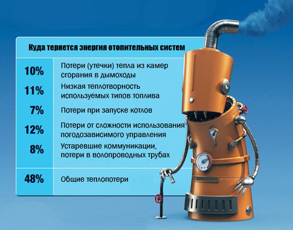 Water thermal systems are single- and two-pipe, less often - multi-pipe. In apartment buildings, a two-pipe system is most often used, when hot water enters the premises through one pipe, and returns to the CHP or boiler room through the other pipe, having given up the temperature. A distinction is made between open and closed water systems. With an open type of heat supply, consumers receive hot water from the supply network. If water is used in full, a single-pipe system is used. When the water supply is closed, the coolant returns to the heat source.
District heating systems must meet the following requirements:
- sanitary and hygienic - the coolant does not adversely affect the conditions of the premises, providing an average temperature of heating devices in the region of 70-80 degrees;
- technical and economic - the proportional ratio of the price of the pipeline to the fuel consumption for heating;
- operational - the presence of constant access to ensure the adjustment of the heat level depending on the ambient temperature and season.
They lay heating networks above and below the ground, taking into account the terrain, technical conditions, temperature conditions of operation, and the project budget.
When choosing a territory for laying a heat pipeline, it is necessary to take into account safety, as well as provide for the possibility of quick access to the network in the event of an accident or repair. In order to ensure reliability, heat supply networks are not laid in common channels with gas pipelines, pipes carrying oxygen or compressed air, in which the pressure exceeds 1.6 MPa.
1 Initial data
2.1.1 Source
heat supply is a CHPP as part of AO-Energo, which is part of RAO UES of Russia.
On balance
AO-Energo are main and part of distribution water TS,
the main part of the distribution and quarterly networks are operated
municipal enterprise; TC for industrial enterprises, constituting an insignificant
share of all vehicles are on the balance sheet of industrial enterprises.
Attached
heat load under the contracts is 1258 Gcal/h; including
household 1093 and industrial 165 Tkal/h; heating and ventilation
thermal load is 955 Gcal/h, the maximum load on hot
water supply (according to a closed scheme) - 303 Gcal / h; heating and ventilation
utility sector load — 790 Gcal/h, including heating —
650 and ventilation - 140 Gcal / h.
approved
AO-energy temperature schedule for heat supply (figure of these Recommendations) - increased, calculated
water temperatures 150/70 °С at the estimated outdoor air temperature tn.r. = -30 °С, with cutoff 135 °С, straightening for hot
water supply (DHW) 75 °С.
2.1.2 Thermal
two-pipe dead-end network; TS are made mainly by underground channel and
overhead on low supports with a gasket, other types of gaskets (channelless, in
passage channels, etc.) occupy an insignificant volume (in terms of material
characteristic). Thermal insulation is made of mineral wool products.
Duration
heating period 5808 hours, summer - 2448, repair - 504 hours.
2.1.3
The material characteristics of the TS on the balance sheet of AO-energos by sections are presented in
table of these
Recommendations.
2.1.4
Monthly and average annual values of outdoor air and ground temperature
(at the average depth of the pipelines) according to local
meteorological station or climate guides, averaged over
the last 5 years are shown in the table
of these Recommendations.
2.1.5
Monthly average values of the temperature of the network water in the supply and return
pipelines according to the approved temperature schedule for heat release at
average monthly values of outdoor air temperature and average annual values
network water temperatures are given in the table of these Recommendations.
2.1.6 Results
tests to determine heat losses in the form of correction factors to
specific heat losses according to design standards are: on average for
overground laying - 0.91; underground - 0.87. Tests were carried out in 1997
g. in accordance with RD
34.09.255-97 [].
Tests
sections of main line No. 1 CHPP ÷ TK-1 and TK-1 ÷ TK-2 were laid above ground with external
with diameters of 920 and 720 mm with a length of 1092 and 671 m, respectively, and sections
highways No. 2 TK-1 ÷ TK-4 and TK-4 ÷ TK-6 underground
channel lining with outer diameters of 920 and 720 mm length
88 and 4108 m, respectively. Material characteristics of the tested networks
accounts for 38% of the entire material characteristics of the TS on the balance sheet of AO-Energo.
2.1.7 Expected
(planned) supply of thermal energy, determined by the planned economic
services of the energy supplying organization by months and for the year, is given in the table of these Recommendations (excluding
amount of heat at industrial enterprises).