Design features
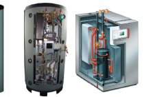
Most often, a metal tank with a capacity of up to 5 liters with built-in pipes acts as a heat exchanger. There is no direct contact with fire. The device allows you to heat cold water, which then enters the radiators or a larger capacity removable tank located in the same or an adjacent room.
As a result, heating the stove in one room, it will be possible to heat another. According to its design, the heat exchanger for the furnace can be external and internal.
This type is very similar to a tank filled with coolant. Inside the tank is a part of the pipe used to remove combustion products. In terms of its design, the external heat exchanger is more complex than the internal one, since it imposes increased requirements on the performance of welding work.
However, its maintenance is much easier. If necessary, the tank can be dismantled in order to remove scale or eliminate leakage.
Interior
It is mounted above a fire chamber directly in the furnace. It is easy to install, but if maintenance is necessary, certain difficulties may arise. Especially if the oven is made of bricks.
To avoid this, at the time of design development, it is worth taking care of the maintainability of the future heat exchanger.
Pros and cons of the oven
An ordinary stove distributes heat unevenly: it is very hot right next to the stove, and the farther away, the colder it gets. The presence of a water circuit allows the heat generated by the stove to be evenly distributed throughout the house.
 Construction of a heating furnace with a water circuit
Thus, only one stove is able to heat several rooms in the house at the same time. The stove works almost the same as a solid fuel boiler. Only it does not just heat up the coolant and the water circuit. In addition, the walls and smoke channels are heated, which also play an important role in the heating process.
The heat exchanger (coil) is the main element of the stove. It is installed in the fuel part of the stove, and there the entire water heating system is connected to it.
The advantages of a furnace with a water circuit include the following features:
- First of all, for such a furnace it is not necessary to purchase expensive units and components.
- A properly built oven will serve you for a long time without requiring expensive repairs. Sometimes, you may only need a small cosmetic.
- You can create a stove of any design: shape, size, decoration - all this is according to your taste and financial capabilities.
- If we compare a stove equipped with a water circuit and a solid fuel boiler, then with the help of the first one, not only the coolant is heated, but also the smoke outlets.
- A coil can be equipped with an already built stove. It can also be inserted into the cooking oven.
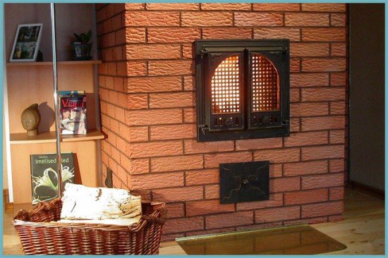 A stove option that fits perfectly into the interior of the room
There are also disadvantages to this type of heating.
- When the heat exchanger is inserted into the fuel part, the precious space of the latter is greatly reduced. The problem can be solved if the heat exchanger is built into the furnace at the stage of its construction. It just needs to be enlarged. Well, if it is inserted into an already built structure, then there is no other way out, except for the incomplete laying of fuel, but in parts.
- With such a stove, the fire hazard increases. An open fire burns in the stove and fireplace, plus spare firewood is often stored nearby. Do not leave this unit unattended.
- If the stove is operated incorrectly, then carbon monoxide entering the premises of the house can lead to very sad consequences.
 An image from which it becomes clear that it is better not to leave the unit unattended
Experts advise using non-freezing liquid in such structures if people do not live in the house all the time, but, for example, only in the summer.
Latest announcements
-
Gas boiler Protherm (Proterm) Bear 20 klom
Brand new in box, all sealed, check warranty dated 09/01/19. I am selling because it did not fit our old system, but to return ...
- Region: Moscow region
-
11.09.19
-
Water-heating gas boiler VK-21 (KSVa-2.0 GS)
We offer a steel water-heating boiler KSVa-2.0 Gs (VK-21). For a wholesale order (from 2 boilers) a price discount is possible
A type …- Region: Kirov region
-
05.08.19
-
Steamer KV-300
We offer steam boiler KV-300(KP-300).
Steam capacity for normal steam, kg / hour - 300;
- allowable excess ...- Region: Kirov region
-
28.06.19
-
Steam generator for 500 kg of steam
Specifications:
— steam capacity — 500 kg/h;
– type of boiler – two-way, fire-tube with reversible…- Region: Kirov region
-
28.06.19
-
Steam generator for 1600 kg of steam
Specifications:
— steam capacity — 1600 kg/h;
– type of boiler – two-way, fire-tube with reversible…- Region: Kirov region
-
28.06.19
-
Hot water boiler KSV-0.63
We offer a hot water boiler KSV-0.63.
Technical data and characteristics:
- nominal heat output, ...- Region: Kirov region
-
28.06.19
-
Hot water boiler 850 kW gas diesel
Specifications:
- nominal heat output - 0.85 MW;
- efficiency - 92%;
– boiler type – two-way, …- Region: Kirov region
-
28.06.19
-
Automatic coal boilers Lugaterm
The boiler model combines three main parts: a water-cooled firebox, a heat exchanger with an automatic mechanical …
- Region: Moscow
-
15.03.19
-
WATER HOT SOLID FUEL BOILERS ON THE KVR MINE
Type of fuel: firewood of any humidity
Power from 0.2 to 2.5 MW
Purpose: obtaining hot water with a nominal temperature ...- Region: Kirov region
-
05.02.19
-
WATER HEATING BOILERS FOR WORKING ON WASTE OF WOOD PROCESSING AND SAWING KVM
Type of fuel: woodworking waste (sawdust, wood chips, bark) – without humidity limitation
Power: 0.2 to 2.5 MW
Purpose:…- Region: Kirov region
-
05.02.19
Announcements by topic:
- Boilers and equipment for boiler rooms
- cooling towers
- Heating networks (all about pipelines)
- materials
- Water treatment
- cogeneration
- Autonomous heat supply
- Pumps, fans, smoke exhausters
- Pipeline accessories
- Heat exchange equipment
- Metering devices
- I&C
- Repair Equipment
- Heating appliances
Design features
If the owner of the building has experience in laying bricks or furnace work, installation can be done by hand. Before connecting the water heating system, you will also need to make a heat exchange unit.
Despite the fact that the construction market offers a large selection of finished structures, self-production is more profitable. A self-made installation allows you to take into account all the parameters of this particular furnace, its placement and dimensions of the fuel compartment.
Pipe heat exchanger
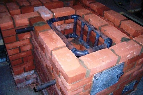
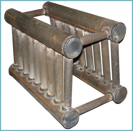
The device of a furnace heating system with a water circuit involves the installation of a heat exchanger in the fuel compartment of the furnace and the connection of pipes to it for supplying the working fluid. For heating and cooking stoves and stoves, coils welded from pipes and placed in metal containers are well suited. Their manufacture requires professionalism, and cleaning from combustion products is quite laborious, but the sinuous surface will provide fast heating.
The 50-mm U-shaped pipes used in the design can be replaced with sections of 40x60 mm profile pipes.This will simplify welding work and greatly facilitate installation. If the oven is not used for cooking, additional small diameter tubes are welded to the top of the heat exchanger. A do-it-yourself design will give off much more heat.
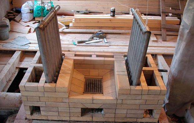
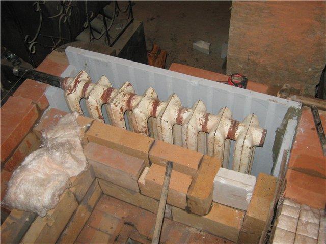
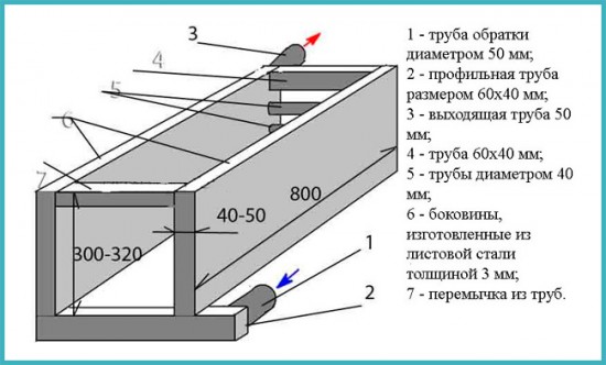
Sheet steel heat exchanger
Devices of this type are used in ovens designed exclusively for space heating. For their manufacture, you will need sheet metal half a centimeter thick, sections of rectangular pipes 40x60 mm, as well as round tubes of the same diameter for supplying water to the working surface. The dimensions of the heat exchangers depend on the dimensions of the furnace compartments for fuel.
A similar heating system can be used for a heating and cooking stove or a simple stove. To do this, the structure must be mounted so that the heated gases from the fuel chamber move towards the upper shelf of the register, flow around it and enter the smoke channels.
Control of welded joints and bends
Each welded joint is subjected to external inspection and measurement to detect edge displacement and fracture at the joint (Fig. 8). Under the displacement b of the edges to be welded is meant the parallel displacement of the axes of the pipes between themselves. The kink k is a deviation in the form of a misalignment of the axes of the joined pipes. Edge displacements and joint breaks are measured with a special ruler 400 mm long with a cutout in the middle, which is installed tightly along the generatrix of one of the pipes with a cutout at the joint, and the deviation is determined on the other pipe with a probe at a distance of 200 mm from the joint axis. Measurements are carried out in 3 - 4 places around the circumference of the joint.
Inspection reveals such defects as arson (melting) of pipes at the points of contact with the sponges and the machine body, creeping edges, incomplete removal of external burr.
a - displacement; b - fracture;
Figure 8 - Deviation of welded pipe edges
To check the quality of welds, as well as devices for automatic control of the parameters of the welding process, express tests of control welded joints (samples) are carried out. Samples are received before the start of each shift. Welding is only allowed if there are positive results of rapid tests of control samples. As a rule, express samples are subjected to metallographic examination.
Checking the mechanical properties and metallographic examination of welded joints are carried out on samples made from control welded joints, or on samples of welded joints cut from the manufactured product. In the case of cutting out from finished products, the volume of control joints should be at least 1% (but not less than three joints) of the total number of identical welded joints performed by each welder in one shift.
By running the ball with compressed air, the completeness of the removal of the internal burr (or metal leakage) is checked - ensuring a given flow section in welded joints. When testing welded joints on straight pipes (lashes), a ball with a diameter of 0.86d is usedin.nom, on coils 0.8din.nom pipes. The decrease in the diameter of the ball during the control of the flow area in the coil is caused by the ovality of the pipes in the bends. A ball trap is put on the free end of the coil, which ensures the safe operation.
The control of ovality of pipe bends and coils of heating surfaces is selective (at least 10% of bends of the same standard size). The maximum ovality along the entire length of the bend should not exceed the allowable value. Measurement of the maximum and minimum outer diameters of the pipe at the place of the bend is carried out in one control section.
The ovality of the section in the places of pipe bends can be determined
where and are, respectively, the maximum and minimum outer diameter of the pipe at the bend, measured at one section of the section, m.
Permissible ovality for boiler heating surfaces
where R is the pipe bend radius, m;
- outer diameter of the pipe, m.
The thinning of the pipe wall at the place of the bend on the stretched (outer) side is determined selectively by an ultrasonic thickness gauge. A mandatory check of thinning is recommended when changing bending tools, setting up the machine and fixtures.
For pipes with a diameter of up to 60 mm, bent without heating, high-frequency currents (HF), waviness (corrugations) on the inside of the bend and bulges on the stretched side should not exceed 0.5 mm in height with a minimum step of at least three heights.
Choosing a material
The coil is traditionally made of a pipe, the length and diameter of which are determined by the desired level of heat transfer. The efficiency of the structure will depend on the thermal conductivity of the material used. The most commonly used pipes are:
- copper with a coefficient of thermal conductivity of 380;
- steel with a coefficient of thermal conductivity of 50;
- metal-plastic with a coefficient of thermal conductivity of 0.3.
Copper or plastic?
With the same level of heat transfer and equal transverse dimensions, the length of metal-plastic pipes will be 11, and steel pipes 7 times longer than copper pipes.
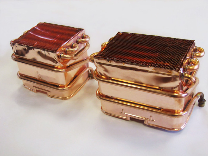
That is why for the manufacture of the coil it is best to use annealed copper pipe.
Such a material is characterized by sufficient plasticity, and therefore it can easily be given the desired shape, for example, by bending. A fitting is easily connected to a copper pipe with a thread.
We are looking for improvised means
Given the high cost of materials, it would be appropriate to consider the possibility of using products that have already served their purpose, but have not yet fully developed their resource. This will not only reduce the cost of manufacturing the heat exchanger, but will reduce the time for installation work. As a rule, preference is given to:
- any heating radiators that do not have a leak;
- heated towel rails;
- car radiators and other similar products;
- instantaneous water heaters.
Payment
Minimum bending radius
The bending radius is determined by the formula
=3,0833,
where is the bending radius, mm.
Based on this condition, it is required to apply bending by winding with a mandrel (2 based on design considerations).
Definition of bending moment
The bending moment required for pipe bending is determined from the pipe bending condition:
,
where is the stress in the deformation zone, MPa;
- conditional yield strength of steel, MPa;
=255 MPa for steel 15Kh1M1F.
The opening of the bending condition is determined by the formula
,
where is the pipe strengthening factor determined by the section shape;
is the pipe strengthening factor, determined by the properties of the material;
For tube bundle:
= 5.8 for steel 15Kh1M1F.
Determination of the moment of resistance, , Nm of the section for elastic bending is determined by the formula
where
The ratio of inner to outer diameter is determined by the formula
The moment of resistance is determined by the formula
The bending moment is determined by the formula
Determining the clamping force of the pipe
is determined by the formula
\u003d (1.5-2.0) \u003d 2.00.032 \u003d 0.09 m.
The clamping force of the pipe is determined by the formula
Determining the required radius of the bending sector
During cold deformation of metal, including pipes, springback occurs - the ability of the pipe to unbend somewhat after the load is removed. Therefore, it is necessary to determine the radius of the bending sector, R, m, which would reduce this effect.
The radius of the required bending sector is determined by the formula
where E = 2.1.
Bending Angle Determination
The bending angle is determined by the formula
where
is determined by the formula
The bending angle is determined by the formula
Determination of the total torque
The total torque is determined by the formula
where is the torque required to overcome friction forces, kNm.
Determination of the torque required to overcome the forces of friction
,
where is the resulting friction coefficient (empirical), taking into account the rolling friction on the roller, the sliding friction of the roller on the axles, the sliding friction in the bearings of the bending sector, the friction of the pipe on the mandrel, etc.
=0,05.
The torque expended to overcome the friction forces is determined by the formula
The total torque is determined by the formula
Determining the power on the bending sector shaft
Power on the shaft of the bending sector
where
is determined by the formula
where =1450 rpm (accepted);
= 450 (accepted), the drive itself is unknown to us, so all data is speculative.
The power on the bending sector shaft is determined by the formula
The power of the drive motor is determined by the formula
where is the efficiency factor (C.P.D.) of the drive (accepted conditionally).
Analysis of the calculation of the pipe bending process
In the course of this calculation, the required pipe bending radius was determined, the value of which showed that it was necessary to apply winding bending with a mandrel. The required torque on the shaft of the pipe bending sector was found, the value of which made it possible to determine the required power of the drive motor for pipe bending. Its value is not so great (1.895 kW), but it is enough to bend pipes of this diameter.
Methods for manufacturing coils
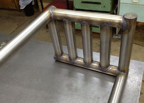
There are three main schemes for obtaining coils of boiler heating surfaces (Fig. 7): element-by-element, wicker and the method of sequential build-up. Regardless of the method, the technological process for manufacturing coils provides for: incoming inspection of pipes; sorting the original pipes by length; development of schemes for cutting pipes into elements; pipe cutting, trimming and cleaning of pipe ends. We choose the element-by-element method.
Figure 7. Element-by-element scheme for the manufacture of coils
With the element-by-element manufacturing method, the prepared straight pipes are first bent on machines with subsequent plating, then the bent elements are welded together into a coil (Fig. 7).
Disadvantages of furnace heating with a water circuit
- Loss of usable space. The heat exchanger built into the firebox significantly reduces its size, so this factor must be taken into account when laying the firebox. Well, if the heat exchanger is built into an existing structure, the only solution is frequent fuel loading.
- Increased fire hazard. Since a stove or fireplace requires an open fire and a supply of fuel nearby, it is not recommended to leave such a stove unattended for a long time.
Having organized stove heating in the house, you must constantly monitor fire safety
Carbon monoxide. If used improperly, carbon monoxide can enter the living quarters, which is dangerous to human life.
Advice. If heating with a water circuit is installed in a country house in which no one lives regularly, especially in winter, then in order to avoid freezing the water in the circuit, it is better to use an antifreeze liquid.
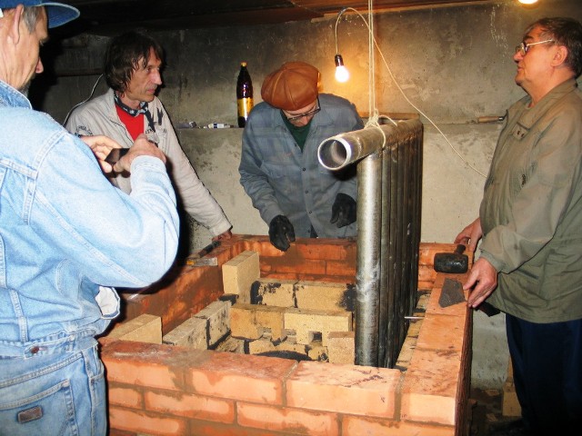
Let's start installation
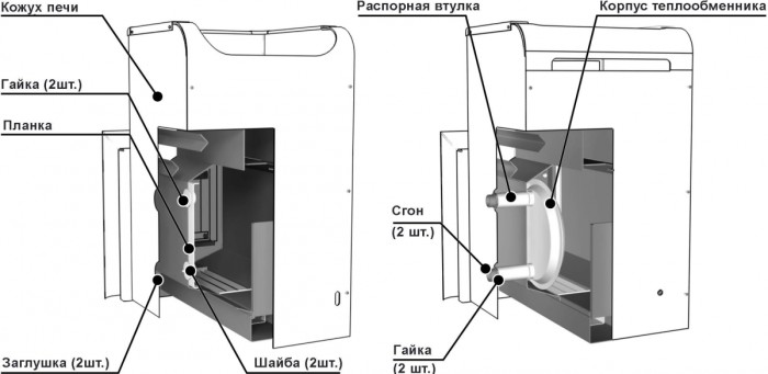
The sequence of work depends on the design features of the heat exchanger.
Installing a device with a register
When installing in an old furnace, you will have to disassemble part of the masonry. The sequence of work is as follows:
- We are preparing the foundation for the coil directly in the furnace cavity.
- Installing the coil.
- We lay the disassembled row of bricks, leaving room for the inlet and outlet of the pipes.
- We connect the heat exchanger to the heating system.
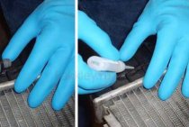
Before starting operation, the tank should be checked for leaks without fail. You can make sure that there are no leaks by filling it with water, preferably under pressure.
Mounting the device with a container
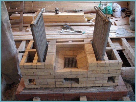
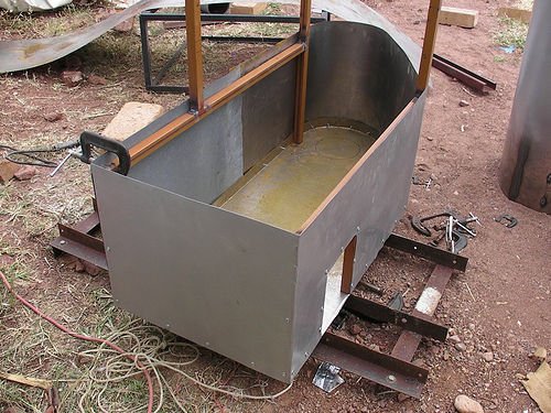
The best option for a stove or fireplace. It is made of a metal tank and two copper tubes. The volume of the tank, as a rule, is about 20 liters.In the absence of a finished product, a reservoir of sufficient volume is made by hand by welding sheet steel.
For the manufacture of the heat exchanger, a material thicker than 2.5 mm should be used. Welding should be done in such a way that the thickness of the formed seam is minimal.
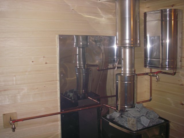
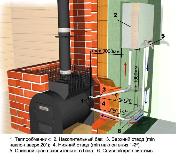
The tank must be installed 1 meter above the floor level, but no further than 3 meters from the stove. Two holes are made in the tank: one near the bottom, the second - at the highest point on the opposite side. The efficiency of heat transfer depends on the location of the lines.
It is necessary to strive to ensure that the minimum deviation of the lower outlet in the direction of the floor is 2 degrees. The top one should be connected at an angle of 20 degrees in the opposite direction.
A drain valve is being installed in the storage tank. Another tap is provided to drain the entire system, which is installed at the lowest point. After checking the tightness, the system is ready for operation. The efficiency of such a furnace with a heat exchanger can be appreciated in the cold season.
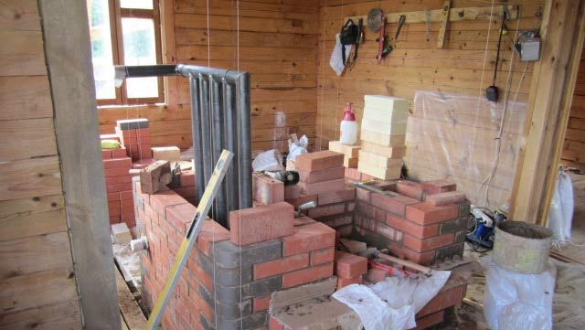
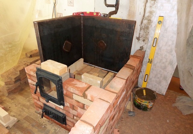
Do-it-yourself stove heating with a water circuit phased construction
First, before you start building a stove, you need to prepare the foundation. To do this, it is necessary to dig a pit, the depth of which is 150-200 millimeters. At the bottom, pour broken bricks, gravel and rubble in layers. Then fill everything with cement mortar. The foundation should rise above the floor by a few centimeters. Lay waterproofing material on the screed.
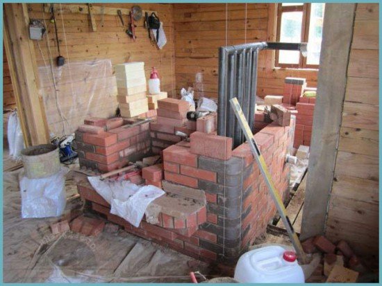 The process of building a furnace with a water circuit
The main features of bricklaying
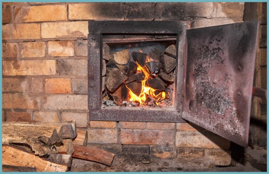
The stove must be built from quality materials. Walls can be built from bricks with normal firing, but for the furnace part, get refractory bricks.
- Before starting laying, the bricks must be moistened. To do this, immerse them in water for a while. When air bubbles stop coming out of them, laying can begin.
- All rows and corners must be tied.
- Apply cement mortar immediately to the entire rad. Its layer should be about 5 millimeters. Freshen the mortar at the end right before laying the brick on it.
- When you get to the furnace part, do not apply clay with a trowel. Do it with your hands.
- Every five rows, carefully cut off excess cement from the seams and wipe them with a damp sponge.
- The walls of the stove must be vertical and horizontal. Use a spirit level at all times during masonry to check this.
Application Specifics
Standard stove heating implies an uneven distribution of thermal energy - the farther from the source, the colder. After connecting the radiators and pouring water, the furnaces act as analogues of solid fuel boilers, providing heating of the coolant, smoke channels and walls. Such a system during the furnace will allow heat to be transferred from the coil to the radiators, and after the fuel is extinguished, it will use the energy of the heated walls of the furnace.
When installing a heat exchanger, it should be taken into account that its installation will reduce the useful volume of the fuel compartment and fuel will have to be added much more often. The correct design of the water circuit and its relationship with the dimensions of the heating chamber will help eliminate this problem. A good alternative would be a long-burning stove.
There are some nuances in such an upgrade of the heating system. The energy that is released during the combustion of firewood will begin to heat the heat exchange unit and the working fluid placed in it, but the furnace walls will not change their temperature.

The upper part of the body with smoke channels will be heated. If the building is used as a temporary residence, the oven will not turn on regularly and may cause the liquid inside the pipes to freeze.In order to prevent accidents, it is recommended to replace water with antifreeze.
Quality indicators
Quality indicators serve to evaluate the operational advantages of the unit, the main ones are: the technical level, reliability and durability, structural, aesthetic and ergonomic characteristics of the unit.
A. Technical level. There are absolute, relative and prospective technical levels.
The absolute technical level of a product is characterized by its performance. Their number should be minimal. In order to avoid multiplicity and fuzziness in assessing the absolute level, it is necessary to limit ourselves only to the most important of them - productivity, efficiency, process continuity, degree of automation.
The relative technical level characterizes the degree of perfection of the product when comparing (by relevant indicators) its absolute technical level with the level of the best modern world - domestic and foreign - samples and models of a similar purpose.
A promising technical level determines the planned and planned trends in the development of a given industry in the form of a set of its prospective indicators.
B. Durability and reliability. These indicators are the most important of the quality indicators.
Durability - the property of the unit to maintain performance with the smallest possible interruptions for maintenance and repairs until destruction or to another limit state. The main quantitative indicators of durability are technical resource and service life.
Technical resource - the total operating time of the unit for the period of operation.
Service life - the calendar duration of the operation of the unit before destruction or to another limit state (for example, until the first major overhaul). The service life is limited by the physical and moral deterioration of the unit.
Reliability is a property of the unit, determined by the reliability, durability and maintainability of the unit. Quantitative indicators of reliability: operating time, probability of failure-free operation, availability factor.
Operating time - the duration or amount of work of the unit,
measured by the number of cycles, the number of manufactured products or other units.
The probability of failure-free operation is the probability that, under certain modes and operating conditions, no failure occurs within a given duration of operation. Availability factor is the ratio of the operating time of the unit in units of time for a certain period of operation to the sum of this operating time and the time spent on finding and eliminating failures in the same period of operation.
B. Ergonomics and technical aesthetics. Creation of modern heat exchangers that meet the best samples and world standards in terms of quality, ease of maintenance and appearance. The design of an industrial heat exchanger should be based on technical conditions and, along with this, on the requirements put forward by new scientific disciplines - ergonomics and technical aesthetics.
Ergonomics is a scientific discipline that studies the functional capabilities of a person in labor processes in order to create perfect tools for him and optimal working conditions.
Technical aesthetics is a scientific discipline, the subject of which is the field of activity of an artist-designer. The purpose of artistic design is (in close connection with technical design) the creation of industrial facilities that most fully meet the needs of service personnel, best suited to operating conditions, having high aesthetic qualities, in harmony with the environment and environment.
Beautiful appearance corresponds, as a rule, to a rational and economical design. The appearance of the product largely depends on its color.Color is the most important factor that not only determines the aesthetic level of production, but also affects worker fatigue, labor productivity and product quality.
Furnace heat exchangers
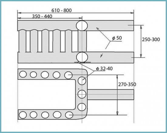
Scheme of arrangement of the coil
The diagram shows one of the options for the coil. It is good to place this type of exchanger in heating and cooking furnaces, because its structure makes it easy to place a stove on top.
In order to reduce the complexity of the manufacturing process, you can make some changes to this design and replace the upper and lower U-shaped pipes with a profile pipe. In addition, vertical pipes are also replaced with rectangular profiles if necessary.
If a coil of this design is installed in ovens where there is no cooking surface, then to increase the efficiency of the exchanger, it is advisable to add several horizontal pipes. Treatment and withdrawal of water can be done from different sides, it depends on the design of the furnace and the design of the water circuit.
Economic indicators
A. Thermal and hydrodynamic perfection. The power expended on pumping heat carriers in the heat exchanger determines to a large extent the heat transfer coefficient, i.e., the overall heat output of the apparatus. Therefore, an important indicator of the perfection of the heat exchanger is the degree of use of power for pumping the coolant to ensure the required heat transfer.
The thermohydrodynamic perfection of the apparatus can be characterized by the ratio of two types of energy: the heat Q transferred through the heat exchange surface, and the work N expended to overcome the hydrodynamic resistance and expressed in the same units for all flows. Thus, the measure of the use of the expended work on the transfer of heat can be expressed by the ratio
The larger the value of E, the more perfect the heat exchanger or its heat exchange surface from the thermohydrodynamic (energy) point of view, all other things being equal. The energy coefficient E is a dimensionless quantity, therefore the numerator and denominator of the expression E = Q/N can be referred to an arbitrary but the same unit, for example, to a heat exchange surface unit (thermal index), to a heat exchange surface mass unit (mass index), or to unit of volume (volume indicator). When comparing devices, the value of E can be attributed to all heat and to all work expended, or to a unit of surface, mass or volume of the device.
The analysis shows that, other things being equal, a change in the speed of the coolant has a different effect on various quantities characterizing the operation of the heat exchanger: the heat transfer coefficient changes in proportion to the speed (or flow rate) to the power of 0.6-0.8, the hydrodynamic resistance is proportional to the speed to the power 1.7-1.8, and the power for pumping the coolant - to the power of 2.75.
With an increase in the speed of the coolant, the power for pumping it grows much faster than the amount of transferred heat, i.e. for a certain apparatus or a certain heat exchange surface, the value of the energy coefficient E decreases with an increase in the speed of the coolant. Therefore, the absolute value of the coefficient E cannot serve as a measure of the thermohydrodynamic perfection of a heat exchanger, but is useful only when comparing two or more devices.
B. Efficiency. The thermal indicator of the perfection of the heat exchanger is its efficiency (efficiency):
where Q1 is the maximum possible amount of heat that can be transferred from a hot coolant to a cold coolant under given conditions; Q2 is the amount of heat transferred from the hot coolant to the cold one, or the heat spent on the technological process.
The maximum possible amount of heat, or available heat, depends on the initial temperatures and the water equivalents of the heat transfer fluids.
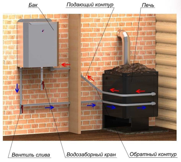
How to install a water circuit
Installation takes place in the same way as installation for any other heating system. The only point to consider is that the “return” for stove heating is located higher.
Coolant circulation is of three types:
- Natural. For natural circulation, the installation of pipes must be carried out at the maximum allowable slope. In addition, in the place where the pipe leaves the furnace, it is necessary to arrange an “acceleration collector”: for this, the pipe is directed vertically to a height of 1–1.5 m, and then down to the radiators along an inclined path.
Forced. This type of circulation increases the efficiency up to 30%. A circulation pump is added to the circuit, which creates the pressure of the coolant. However, it is undesirable to arrange a system with only one type of forced circulation, because in the event of a power outage or a pump failure, the water will not circulate, which will lead to the boiling of the coolant in the system.
Combined. For this type of circulation, it is necessary to combine the installation of pipes with a slope, as described in the first paragraph, with the pump. The pump in this case is connected to the system via a parallel line, as shown in diagram 4. With this combination, the pump will work in the presence of electricity, in its absence, circulation will be carried out naturally.