Display of communications in the drawing
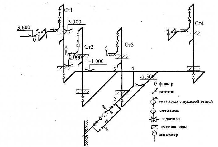
When working with an internal water supply and sanitation project, general drawings are prepared, on which water supply and sewerage are combined. In axonometric diagrams, these networks are always separated. Horizontal sections of networks are transferred to the projection horizontally. On the plan, the risers are located near the serviced group of devices, indicated by large dots. In the diagram, they are built vertically. The riser furthest from the input is depicted in full. The remaining elements are partially performed, indicating their brand. The vertical drawing of the risers allows you to display the valves installed on them.
System details displayed vertically on the project plan are drawn at an angle of 45°. According to the routing, the cold water supply is laid 0.3 m above the floor, located with a slope of 0.002 towards the riser. This position is necessary for the flow of liquid. Connection with water fittings is carried out vertically.
All elements and nodes of the pipeline have their own marking and serial number on the drawing. Symbols show shutoff valves, taps, plumbing fixtures, water meters. In the manufacture of axonometry, the norms for the height of installation of water consumption points are used:
- sink and sink faucet - 1.1 m;
- bath faucet - 0.8 m;
- connection to the water heater - 0.8 m;
- connection to the flush tank - 0.65 m;
- fire hydrant - 1.35 m.
To shut off the flow of water in case of an emergency and for preventive maintenance of the system, shut-off valves (faucets, valves) are installed. They are located in key locations:
- at the base of the risers (in a building from 3 floors);
- at entrances to apartments, ducts to tanks, water heaters, showers;
- at the point of connection to the street network;
- on irrigation valves;
- in the water meter.
Sketch Design Features
Here attention is focused on the reflection of devices. If one element climbs onto another, and this happens in most cases, then a dotted line is drawn indicating the displacement of the plumbing element in order to better visual effect
The axonometric diagram of the water supply system should include readings of all pipe diameters. If the toilet bowl is not marked on the outlet, then take a diameter of 50 mm, if it is, the minimum diameter should be 100 mm
These numbers are important to remember. For risers in 90% of cases, an indicator of 100 mm is used
The slopes in the same diameter will be equal to 0.02, with an indicator of 50 mm, the slope angle is set to 0.03.
If you have already applied all the elements, mark the outlets, the diameter of which is larger than that of the risers, a number of 0.02 is taken as a slope.
At the last stage of drawing up the axonometry, special marks are applied based on the characteristics of the site and the construction plan. Here they note the level of soil freezing, the location of the foundation, as well as other factors affecting edits.
4. Hydraulic calculation of cold water supply
Hydraulic
calculation of the cold water network
start after
constructive solution of the whole scheme
cold water systems,
drawing axonometric calculated
total supply piping schemes
settlement building and quarter.
Target
hydraulic calculation of the internal
cold water supply
is to determine the calculated
costs, pipe diameters
and pressure losses in the design areas
and throughout the system
manner to ensure uninterrupted
water supply for all consumers
in a building with the necessary pressure.
Hydraulic
calculation is carried out in the following
sequences:
Selected
dictating point, taking into account remoteness
and location height
water folding fittings, as well as the magnitude
free
pressure
 for
for
sanitary appliances.
Net
divided into calculated sections.
Estimated
called
area where water flow

constant:
pipeline sections
between connection points
water fittings
To
apartment wiring, apartment
wiring to risers, risers to: highways.
Breakdown into settlement areas
carried out against the direction of travel
water, starting from the dictating point.
Determined
number of devices served
settlement area.
At the same time, watering taps are not taken into account
turn on.
At each site
the estimated water flow is determined,
l/s:
 ,(4.4.1)
where

–
maximum second consumption of cold
water, l/s, referred
to one device. Its meaning is determined
by instrument, consumption
which is the largest. Consumption
one device
defined in
in accordance with clause 3.2.
a –
value determined depending on
of the total number of devices
N in the calculated area and their probabilities
actions RWith.
Her
value
determined according to the table. 2 app. 4 .
Probability
instrument actions Rcfor
different sections of the network is determined
immediately for the entire building as a whole (because
attitude UN
= const).
 (4.4.2)
where
U
–number
inhabitants in the house;
N
–number
all water fittings;
- norm
expense
cold water by one consumer per hour
greatest
water consumption, l / h (app. 3).
 (4.4.3)
 –
–
Ogeneral
water consumption rate per consumer per hour
greatest
water consumption, l / h (app. 3);
 –
–
norm
expense
hot water by one consumer per hour
greatest
water consumption, l / h (app. 3).
Are selected
pipe diameters from table. for hydraulic
calculation
water pipes at estimated costs
and allowed speeds.
It should be borne in mind that the speed
movement of water in pipelines of internal
water supply networks should not exceed
3 m/s. When selecting internal diameters
pipelines of cold
water supply should be guided
for economical
the speed of water movement, which for
pipes d
40 mm –
within 0.9 ... 1.2 m / s.
Losses
head, m, on sections of pipelines
cold water systems should
determined by the formula:
h
= i—l-(l
+ kl),
(4.4.4)
where
i–specific
friction head loss, mm/m;
/
–
length of the calculated section, m;
k–
head loss factor
in local resistance. In networks
utility and drinking water pipelines
residential
buildings are accepted kt=0,3.
Along the main path
from the dictating point to the city
plumbing count the amount
head loss.
Hydraulic
it is convenient to perform the calculation in a spreadsheet
form.
At
presence on the axonometric diagram
different in load (number of devices)
risers, there may be doubt about
the correct choice of the dictating point.
Therefore, to accurately find the dictating
points, you need to find the vanishing point (see tab.
4.4.1.) different risers (usually on the main)
and with respect to it find the sum of losses
pressure on one and the other branches
taking into account the difference of the geometric
installation heights of different devices (if
for dictating
points taken by different devices) and the required
pressure required
for their normal operation. Big losses
define dictating
riser and location of the dictating
points. Such a calculation
also needed to create
material specifications and
equipment for the whole house, as
diameters need to be determined.
all risers and sections of the highway. V
this case the table
will take the form:

( );
);

Compared
values and
and .
.
Selected as dictator
riser, value
 on the
which is more.
Note:
Should
remember that the section from the TsTP to the city
plumbing (input
possession) should be calculated at and
and
 .
.
What to look for when sketching
Before reflecting the axonometric scheme of space heating in paper form or in electronic form, a number of calculations are carried out. The scheme itself is based on the collected data:
- values of heat demand for the rooms of the building;
- typology of heating devices, their number for each of the rooms;
- the main decisions regarding the entire engineering network: the use of risers, the calculation of hydraulic branches and circuits, the procedure for connecting elements of the heating system;
- characteristics of pipeline sections: diameters and lengths of pipe fragments, valves, thermal controllers, hydraulic regulators.
Having received the corresponding calculations, their indicators are entered into the scheme. The axonometric diagram of the heating system necessarily contains the technical characteristics of each of the network nodes (boilers and pumps used), the length and diameter of pipes, heat consumption and information about other thermal properties of heating devices, such as radiators, convectors, registers.
Starting work on an axonometric drawing, first of all, they determine the main ring of movement of the coolant - the path to the most remote of the elements from the boiler and back.
Summing up what has been learned, let's say that axonometry is performed without fail, regardless of the type of communication system for structures of any type of purpose. Having a graphic drawing in front of their eyes, installers quickly determine how much work needs to be done and how exactly the network looks.
If the specialist understands the axonometric heating scheme, and the drawing itself is made correctly without any errors, then during the project implementation it is possible to eliminate any difficulties associated with the installation of elements of the heating system, pipelines and other engineering networks.
In order for the design, and after the installation of the water supply, to be successful, it is necessary to correctly visualize on a sheet or in electronic form the building itself and the communication branches inside it. In this case, the graphic component of the project includes:
- building master plan;
- situational diagram;
- facade;
- plans for each of the floors;
- roof plan;
- axonometric diagrams: ventilation, heating, plumbing;
- cuts and other concepts.
Remember that when working with a correctly designed axonometry, there are no problems with the installation of engineering networks in 99.9% of cases. Because this stage is so important in designing a future house or high-rise building.
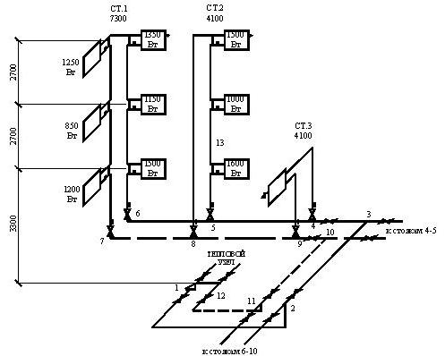
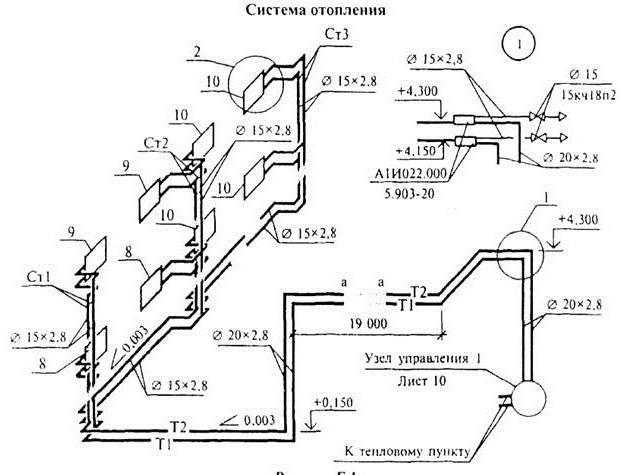
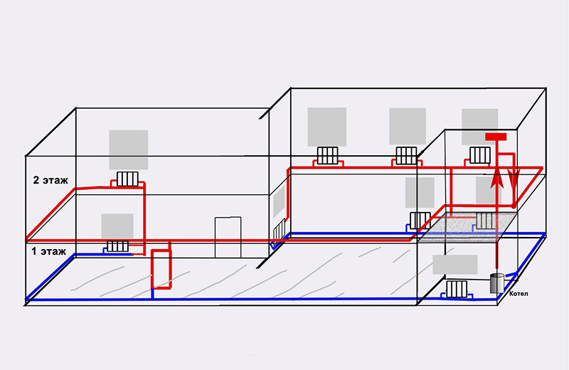
Heating schemes for private houses are different. For example, single- or double-circuit, with natural or forced circulation of the coolant, but when the phrase “axonometric diagram of the heating system” is pronounced, many people wonder what kind of scheme this is. To know what an axonometric heating scheme is, you need to imagine what axonometry is in principle. 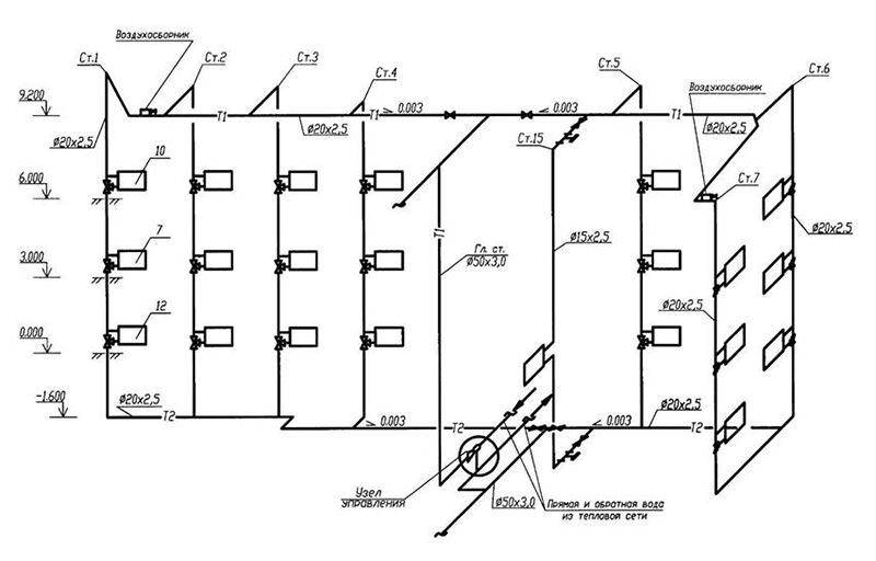 An example of an axonometric heating scheme
How to reflect structural elements in electronic form
The fastest way to build a drawing is by cloning the entire circuit. To do this, select the "Insert" command, after which the integrated image is turned over. In order for the function to be executed, it is given a value equal to 45 degrees (a number is written in the program).
Having prepared the basis in the electronic version, where the risers are marked on the plan, they put symbols in the form of dots. To reflect all the floors in the building, a vertical line is drawn. For the purpose of better perception, overlapping panels are reflected in the diagram.
Important! Don't make the slabs too long. Take advantage of the gap
A feature of the axonometric sewerage scheme is the reflection of all elements of sanitary devices: urinals, toilet bowls, sinks, drains and other devices for hygiene procedures.
Axonometry of plumbing, heating, sewerage
According to GOST 2.317-2011, all axonometric diagrams related to sanitary and technical systems of water supply, sewerage, heating are built in frontal dimetric (oblique) isometry with the left coordinate system.
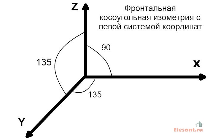
Accordingly, the dimensions along the z and x axes will be without distortion, and along the y axis, they will be half as large.
You ask, what does this drawing have to do with pipes and plumbing installation? Now imagine that the planes along the axes of axonometry are the walls of your house or apartment. Plumbing pipes, water pipes, sewerage and heating pipes run along the walls, vertically or horizontally. This means we can draw the pipe paths in axonometric view without showing the walls themselves.
This will give very clear drawings of how and where to install plumbing wiring. Moreover, plumbing fixtures are applied to the axonometric diagram in symbols, pipe diameters are applied, explanations are made, tables on materials and equipment are compiled for the diagrams. As a result, you have in your hands a detailed guide on how to install plumbing in a house (apartment), which practically excludes installation errors.
Definition of an axonometric heating scheme
Axonometry is one of the sections of applied drawing that studies, examines and provides an opportunity to obtain fairly accurate images of any objects in two or three projections. A rectangular axonometric projection is when the lines that project the image of an object are located perpendicular to the axonometric projection plane. Rectangular projection includes isometric and dimetric. If the projection angle is not equal to 90 °, then such a projection is called an oblique axonometric projection. It also includes frontal dimetric and trimetric projections.
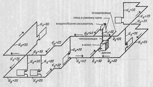
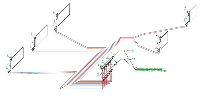 Collector wiring in oblique axonometric projection
It follows from this that an axonometric heating scheme is any scheme of any heating of a multi- or low-story building, made in axonometry, and not in one plane. This helps to visualize the wiring and other elements of the heating system in real terms. With this approach to displaying heating elements, the projection of each object is performed as follows:
- The element is located on the scheme according to all three coordinate axes;
- The "picture plane" is defined - the element will be projected onto it. In this case, the "picture plane" should not run parallel to any of the coordinate axes;
- The projected node or element is completely transferred to the diagram.
Requirements for drawing up drawings of heating and other systems of a residential or industrial building are defined in GOST 21.602-2003. All heating elements and assemblies according to GOST have their own designations: this is a marking and a serial number included in the drawing. The following notation is used:
| Element or Node | Marking |
| heating riser | St |
| Main heating tower | gst |
| Compensator | TO |
| Horizontal piping | GW |
| Thermometer | T |
| pressure gauge | R |
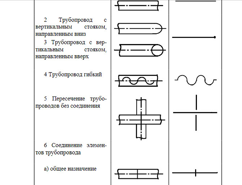 Fragment of GOST 21.206-93 on the designations of pipes and pipeline connections
According to GOST 21.206-93, piping systems are indicated graphically. This applies to the following nodes:
- Common pipeline;
- Vertical riser pointing down;
- Vertical riser pointing up;
- Flexible pipeline;
- Pipe crossing without connection;
- Simple connection of the pipeline or its elements;
- The connection of the pipeline or its elements is flanged;
- Coupling threaded connection;
- Coupling connection quick disconnect;
- Socket connection.
Designations of valves, radiators and other elements are displayed in GOST 21.205-93. For example, such as:
- Wash basin;
- Foot bath;
- Toilet;
- heating thermostat;
- Shower net;
- Air Dryer.
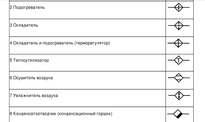 Fragment of GOST 21.205-93 on the designation of valves
Any axonometry cannot be displayed by standard means allowed in GOST, and there are additional requirements and permissions for this. For instance:
- Elevation and level marks can be placed outside the element or indicated directly on the contours of objects;
- An axonometric drawing of a heating circuit with a bottom wiring or any other circuit can be made on a scale of 1:50, 1:100 or 1:200.
List of equipment and parameters on the diagram
On the heating scheme of any floor should be indicated:
- Pipe wiring with indication of all pipe diameters;
- Sections of pipe insulation - length and thickness. Such thermal insulation is indicated graphically;
- Piping axes relative to zero level;
- Pouring slope angles;
- If there are gaps in the horizontal sections of the spills, then the dimensions of these sections are indicated;
- Support and suspension elements, compensators.
Mandatory requirement: you must specify the type and main characteristics of these elements:
- How many sections does the heating radiator contain;
- How many sections or pipes are in the heating register, its diameter and total length;
- For other heating devices (convectors, radiators) - the type of device;
- Designations of thermal installations (boilers, heating furnaces and heat exchangers, circulation and thermal pumps, elevators, etc.);
- Mortgage equipment;
- Measuring instruments.
 Heating diagram to scale
Heating equipment and calculations
All equipment used in the heating system is divided into auxiliary and main. The main one is a boiler or other heating device, the auxiliary one is radiators and distribution pipes with the attached fittings. To calculate the parameters of the necessary heating equipment, the specific power of the boiler is required, which varies depending on the climatic zones:
- For regions of the Far North - 1.5-2.0 kW;
- For the temperate climate zone and central regions - 1.2-1.5 kW;
- For the southern belts - 0.7-0.9 kW.
Based on these amendments, the power of the heater is calculated by the formula:
Wboiler = S x W / 10;
Where W is the calculated power of the heating device (boiler, convector, etc.);
S is the total area of the heated object. 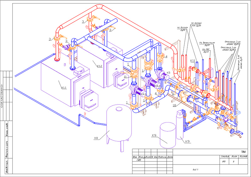 Axonometric diagram of boiler equipment with two burners
Pumps are thermal and circulation. In most cases, except for low-rise buildings with natural circulation of the coolant, it is impossible to do without pumping equipment, therefore, these devices are present in almost all schemes. Pumps must meet certain technical requirements, including the following:
- Ease of installation, dismantling, ease of operation and maintenance;
- Low noise and cost-effectiveness of the device;
- Reliability and duration of operation.
In low-rise residential buildings, three types of heating systems are used:
- The classic two-pipe scheme, according to which hot water is supplied through one pipe and returned through the second. In this scheme, the pump is mounted on the return;
- Scheme with a vertical riser. In this scheme, hot water is also supplied to the radiators through one pipe, and returns through the second, but the circulation pump is installed on the outlet pipe to supply the hot coolant. Thus, hot water first passes through the upper radiators, and then moves to the lower batteries of the system;
- The single-pipe scheme involves the movement of the coolant in series from the radiator to the radiator with a return to the boiler. This is the simplest scheme, but due to its low efficiency, it is used in small one-story buildings.
 Simplified axonometric two-pipe scheme
Calculations when drawing up a heating scheme should take into account:
- Heat consumption in each room;
- Type and number of radiators;
- The number of risers, if any, as well as the total number of branches and circuits;
- The scheme of connection of heating devices;
- Parameters of pipes and valves.
After completing the calculations of the heating system, they must be indicated on the diagram. The main purpose of the axonometric heating diagram is a graphical display of all parts and elements, but, in addition, the diagram should also display the technical characteristics of the heating equipment. Also, the scheme should contain calculations for the supply of heat to each room of the house, including utility rooms.
What is a collector piping
With collector wiring for heating, heating pipes are connected to heating radiators from a single distribution unit. The distributing unit (collector) is a device with one inlet and several coolant outlets. Each output of the heat carrier (water) is independently blocked by a shut-off valve. That is, if necessary, you can turn off separately any radiator of the heating system, regardless of the others.
For heating distribution from the collector to heating radiators, it is carried out with plumbing pipes suitable for heating systems. For heating are used:
- steel heating pipes,
- plastic pipes,
- polyethylene and polypropylene pipes (hot water supply),
- copper pipes.
Heating pipes are connected by special devices called fittings. Heating pipes can have one or two types of connection. So metal-plastic pipes are connected on compression fittings and press fittings. Polypropylene pipes are connected on fittings for welding. Copper pipes are connected at press fittings and compression fittings. Steel pipes are connected with a classic threaded connection, on cast or brass fittings.
Drawing features
When designing an axonometric diagram, pay attention to the following points:
- Plumbing and other appliances connected to the risers and distribution network are reflected only when the necessary diagrams are not in the attached documentation.
- The zero mark (ground floor level) is shown on the risers by drawing a thin horizontal line. In the case of detailing the project, each of the nodes of the drawing is considered separately, reflecting it on an enlarged scale.
- If necessary, symbols for shut-off and control valves, watering taps and other system elements are added to the sketches of diagrams and drawings of water supply networks and sewerage.
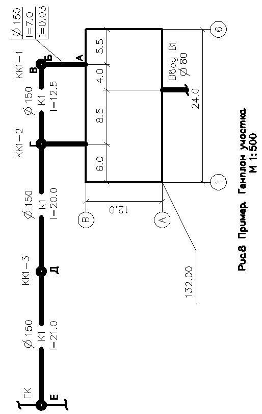
2. Yard sewer network
Yard project
sewerage network is carried out on the master plan
area on which the route is applied
sewer network from outlets from
buildings before connecting to the city
well and water supply entry area. (
Figure 8)
According to
the minimum diameter of the yard network can
be 150mm. Slopes are assigned depending on
from the diameter according to table 4.
On the sewer network
put down wells:
-
on releases;
-
on turns (
if they are according to the trace) -
on connection to
city network; -
on linear
plots.
Distance between
wells on the network Ø150 should not exceed
35 meters
at Ø200-50m.
Table 4
|
Diameter, mm |
bias i |
|
|
min |
Valid for justification |
|
|
150 |
0,008 |
0,007 |
|
200 |
0,007 |
0,005 |