4. Automation of air curtains
Air-thermal
curtains are widely used in
industrial and civil buildings.
Veils make it possible to maintain
during the cold season in production
premises required by sanitary
standards, the parameters of the air environment and at
this will significantly reduce the cost
heat.
At
automation of air curtains
the following tasks are solved:
- start
and stop the curtain, respectively, at
opening and closing the gate;
- the change
supply air curtain fan
depending on the outdoor temperature
air;
- the change
heat dissipation air heater air curtain
depending on the outside temperature
air or air temperature in
room near the gate;
- stop
curtains and simultaneous automatic
shutdown of the coolant supply to
air heater.
On the
rice. 5.5. the automation scheme is presented,
and in Fig. 5.6 the principal electrical
air-thermal control circuit
curtain, which are widely used in
industrial and civil buildings.
Start
electric motors M1
and M2
curtain fans can be carried out
control keys SA1
and SA2
from the local control cabinet or
automatically.
At
automatic air control
veil control keys SA1
and SA2
set to position A
(automatic) (Fig. 5.6). In this mode
when the gate is opened, it closes
contacts SQ,
limit switch, works
intermediate relay TO1
and magnetic starters turn on KM1
Rice. 5.5. Scheme
air curtain automation

Rice. 5.6. Electrical
control circuit diagram
air-thermal
veil
and
KM2,
which closing their power contacts
KM1
and KM2,
turn on electric motors M1
and M2
fans. Close at the same time
auxiliary contacts TOM1
and KM2
magnetic starters that supply
voltage on THEM
MV1 valve
on the heat carrier. The valve opens.
When closing the gate, the contacts SQ
limit switch open and
if the temperature in the gate area is higher
settlement (contacts STO
open), then the relay TO1
and magnetic starters KM1
and KM2
fans are turned off. Simultaneously
break contacts close TOM1
and KM2
in chain IM MV1
and the coolant valve closes.
At
closed gates, in case of lowering
temperatures in the gate area, contacts STO
temperature sensors close and
the air curtain turns on. At
increase in temperature to the set
(calculated) value contacts STO
open and the air curtain
turns off. as a sensor
temperature sensor can be used
temperature chamber bimetallic
DTKB-53.
If
air curtain provides
fan supply control at
change in outdoor temperature,
then additionally set
proportional controller, which
when the outside temperature drops
air below the calculated gives a signal
on the THEM
fan guide vanes,
flow-reducing fan
air curtain. With an increase
outside air temperature is
reverse process: guide vane
opens slightly to increase flow
air curtain fan. For
air temperature control in
gate area in such an air curtain
it is advisable to use three-position
(astatic) regulators, e.g.
TE2PZ,
which have been widely used in
automation of supply chambers.
Executive mechanisms
Actuators - include electric drives for air valves and dampers, fans, pumps, compressor units, as well as heaters, coolers, valves, dampers, electric drives and other equipment.
The actuator is called the drive part of the actuator. Actuators are divided into hydraulic, electric and pneumatic. In particular, electric ones can be solenoid (electromagnetic) and with electric motors (electric)
Valves and dampers
Two-way and three-way valves are divided into threaded and flanged. Valves with flange connection are usually equipped with a mounting kit with a seal, and with a threaded connection - fittings and sealing washers. Two-way valves are used as through passage valves that change the flow rate of the working medium. They are mounted in a piping or duct system so that the direction of flow matches the direction of the arrow on the valve body. A typical example of the use of such a valve is a circuit with a local circulation pump.
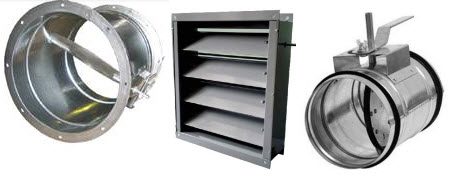
Three-way valves serve as mixing, separating and through valves. These valves are widely used in refrigeration systems. Butterfly valves are flange mounted. The working part of such valves is a disk fixed on a rotating axis. The amount of clearance between the disc and the inner surface of the valve varies depending on the angle of rotation of the axis. Valves of this design are most often used in large diameter liquid pipelines. On air ducts, both round and rectangular, air throttle dampers are used. They are used to regulate air flow at low static pressure. Check valves are needed to prevent the flow of liquid or gas in the opposite direction, in particular, they are used in liquid and suction pipelines of chillers and autonomous air conditioners.
Electric actuators for air dampers
To control air dampers, it is often not enough to manually switch the positions of the valves, therefore, electric actuators controlled remotely or automatically are used. Electric drives are classified according to:
- supply voltage (24V AC/DC or 230V 50Hz)
- torque value (the required value is determined by the area of the air valve on which the actuator is installed)
- control method (smooth, two-position or three-position)
- method of returning to the original position (using a spring or using a reversible electric motor)
- availability of additional switching contacts
Send an application and get a CP
We will select the equipment, reduce the cost of the estimate, check the project, deliver and install on time.
Regulators
The temperature controller provides control of actuators according to the readings of various sensors and is one of the main elements of the system. The simplest type of regulators are thermostats, they are designed to control and maintain a given temperature in various technological processes. Thermostats are divided according to the principle of operation, method of application and design. According to the principle of action, they are divided into:
- bimetallic
- capillary
- electronic
The principle of operation of bimetallic thermostats is based on the operation of a bimetallic plate under the influence of temperature. They are mainly used to protect electric heaters from overheating and maintain the desired temperature in the room.
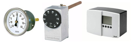
Capillary thermostats are used to control the temperature of heat exchangers in air conditioning and ventilation systems and prevent their destruction due to freezing of the coolant. The components of such a thermostat are a capillary tube filled with R134A freon, connected to a diaphragm chamber, which, in turn, is mechanically connected to a microswitch.
In ventilation systems, the capillary frost threat thermostat can trigger the following processes:
- fan stop
- closing the outside air damper
- start of the heat carrier circulation pump
- activation of the alarm
For rooms in the depths of buildings, electronic thermostats with a relay output are used. Thermostats can maintain the set temperature both by the built-in and by the remote sensor.
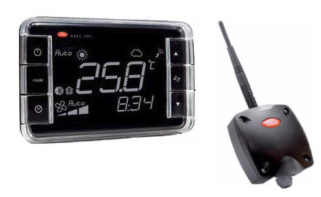
Wireless room terminals - a wireless solution for managing climate parameters (temperature and humidity) in buildings. This approach guarantees energy saving and optimization of the control system. The device is optimally suited for air conditioning systems (rooftops, air handling units) and can be adapted to other systems (e.g. underfloor heating).
The system consists of:
- terminal with built-in temperature and humidity sensors;
- temperature and humidity sensor;
- access points, used to collect information from wireless terminals and sensors and transfer it to the building management system, which is built either on the basis of a controller and a dispatch system server, or using a central control unit;
- a repeater that provides an extension of the coverage area with a radio signal to ensure data exchange between wireless terminals and sensors located in remote locations of the facility.
Advantages:
- Flexibility: The ability to easily change the management structure of engineering equipment, for example, if it is necessary to change the layout of a supermarket or office without making changes to existing communication channels.
- Simplified retrofitting of historical or other buildings where construction work associated with the opening of floors, walls, etc. is difficult or unacceptable.
- Lower cost of installation and operation.
- Simplified system commissioning.
- Integration with most common BMS building management systems.
- Maintaining the set parameters in individual areas of the room (helps reduce energy costs).
- The cellular structure of data exchange between access points and devices ensures high reliability of data transmission within the network.
Application
The Klimat 101 microprocessor controller is a thermostat used to maintain the air temperature in supply ventilation systems with a water heater. It does not require additional settings, the control system is ready for operation immediately upon power-up.
Maintaining the set temperature (from 7 to 99 °C) occurs by controlling the mixing valve drive. The controller constantly monitors the temperature in the ventilation duct and the temperature of the return water from the water heater using sensors connected to it. The Klimat 101 controller uses proportional integral (PI) regulation. This type of regulation is optimal for controlling supply and exhaust ventilation systems, since it allows maintaining the set temperature with great accuracy, reducing temperature fluctuations and preventing the control system from entering into resonance.
For cold regions, there is a winter start function and the ability to adjust the return water temperature in standby mode.
The Klimat 101 controller monitors the presence of air and return water temperature sensors, as well as active protection of the water heater from freezing of the coolant.
The updated version of the software has the following features: - winter start mode, with the ability to set the start time - the ability to view the readings of the return water sensor - the return water temperature setting mode in standby mode - the ability to select the control signal 0-10 V or 2-10 V
Wiring diagram
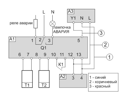
A1 - Klimat 101 controller;
A2 - transformer 24 V.It is possible to use transformer TP12;
T1 - channel (room) sensor TG-K1000 (TG-V1000) with a measuring element Pt1OOO;
T2 - consignment note (submersible) sensor TG-A1000 (TG-D1000) with measuring element Pt1ООО;
AZ - electric drive of the control water valve. Here is a diagram of connection to the actuator AKM115SF132 from Sauter;
Q1 - emergency relay for turning off the fan (this relay can control the operation of the supply fan);
K1 - fan operation confirmation contacts (can be switched on from the PS500 or PS1500 differential pressure sensor).
Sensors
Sensors - they perform the function of their meters in the ventilation automation circuit. They monitor the parameters of the processed air, the operation and condition of the network equipment and provide information to the automation cabinets.
Temperature sensors
They are divided into two types, according to the measurement method:
- thermoelectric converters or thermocouples (operation is based on the measurement of thermoelectromotive force developed by a thermocouple)
- thermal resistance or thermistors (the action is based on the dependence of the electrical resistance of the material on the temperature of its environment). There are two types of such sensors - NTC thermistors (material resistance decreases with increasing temperature) and PTC thermistors (material resistance increases with temperature).
Temperature sensors can be both indoor and outdoor, duct (measure the air temperature in the air ducts), overhead (measure the surface temperature of the pipeline), and so on.
When choosing a sensor, you need to pay attention to the temperature characteristics of the sensing element, they must match those recommended in the description of the temperature controller
Humidity sensors
These are electronic devices that measure relative humidity by changing the electrical capacitance depending on the relative humidity of the air. Humidity sensors are divided into two types: room and duct. They differ from each other in design. When installing the sensor, you need to choose a place with a stable temperature and speed of movement of the surrounding air, and it is also undesirable to place the sensor near windows, under direct sunlight and near heaters.
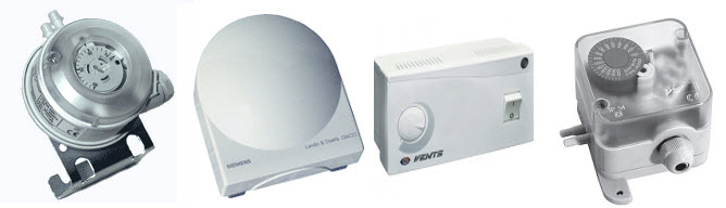
Pressure Sensors
There are two types of pressure sensors - analog pressure sensors and pressure switches. Both types of sensors can measure pressure both at one point and the pressure difference at two points. In this case, the sensor is called a differential pressure sensor.
An example of the use of a pressure switch in climate systems is a pressure sensor that serves to protect the compressor from too low or high freon pressure. Also, differential pressure gauges are used to determine the degree of blockage in the filters of ventilation systems. With the help of analog sensors, the pressure at the measuring point is determined. The measured pressure is converted into an electrical signal by the secondary transducer of the sensor.
flow sensors
The principle of operation of the flow sensor is as follows: first of all, the velocity of the gas or liquid in the duct or pipeline is measured, after which the measured signal is converted into an electrical signal in the secondary converter, then the flow rate of the gas or liquid is calculated in the computing unit. Such sensors are most in demand in the field of heat energy metering. According to the principle of operation of primary transducers, flow sensors are divided into blade devices, narrowing, turbine, vortex, rotary, ultrasonic and electromagnetic.
In ventilation and air conditioning systems, flow sensors are the most common. They respond to the velocity of the gas pushing against a sensor vane which actuates a dry contact microswitch. When the flow velocity reaches the set switching threshold, the contacts close.When the flow rate drops below this threshold, the contacts open. The switching threshold can be adjusted.
Carbon dioxide concentration sensors
According to the content of carbon dioxide in the air, it is customary to evaluate the gas composition of the air in the room. In a ventilation and air conditioning system, the concentration of carbon dioxide can be regulated. (The norm for the content of carbon dioxide in the air is a value from 600 to 800 ppm).
Select sensors based on the following data:
- terms of Use
- range
- required measurement accuracy of a physical parameter
Work description
The controller controls the flow of hot water through the heater, maintaining the set air temperature, controlling the electric drive M1 using the output signal 0 ... 10 V, which is supplied from the terminal 5 of the controller. Transformer A2 must supply 24V to controller A1 all the time, regardless of whether the fan is running. When the fan is off, pins 10 and 11 should be open. In this case, the thermostat will be in standby mode, contacts 1 and 2 are closed. In this mode, the controller displays the air temperature and maintains the return water temperature depending on the setpoint.
The return water temperature is measured by sensor T2. In standby mode, the heater is maintained in a warm state, which is necessary to turn on the supply system in winter. When the fan is turned on, contacts 10 and 11 of the controller should close. To do this, most often use a differential pressure sensor mounted on the supply fan. When these contacts are closed, the controller enters the operating mode.
The moment the system is switched on, the winter start-up procedure begins. This procedure is designed to ensure a guaranteed start of the system in the winter. Because the controller is not equipped with an outside temperature sensor, winter start is carried out every time the system is turned on. The winter start time is set in the set point setting mode. By setting time = 0 minutes, winter start is disabled. The winter launch algorithm is simple and reliable.
In case of extremely low outside temperatures, it is possible to adjust the temperature of the return water maintained in standby mode. To do this, in the setting mode, it is necessary to increase the value to the required level. At the end of the winter start-up procedure, the controller regulates the supply air temperature and controls the return water temperature, continuously reading data from temperature sensors T1 and T2.
The air temperature is measured by sensor T1. Depending on the difference between the current and set temperature, as well as analyzing the P values, the controller maintains the supply air temperature according to the PI law. If I is set to zero, then only according to P - the law for the air temperature in the room.
In any of the operating modes, the controller actively fights against the threat of freezing of the coolant by additionally opening the mixing valve at a low return water temperature from the water heater. If the water temperature drops below +12 °C, the controller begins to slightly open the valve according to the P - law with a fixed coefficient, if the opening value calculated by it is greater than the existing one at that moment. If the return water temperature has reached + 7 °C, the controller switches to the emergency mode and the alarm relay contacts 1 and 2 of the controller open, which should turn off the fan and close the air damper for supply air. Contacts 2 and 3 close at this moment and can be used to indicate an alarm. The control valve opens fully and the red LED “Alarm” lights up on the front panel of the controller. For further operation of the controller, it is necessary to press the "Reset" button on the thermostat keyboard. After pressing this button, the thermostat switches to standby mode.The "Alarm" LED and the alarm relay are turned off only with the help of the "Reset" button on the front panel of the controller or when the power is removed.
Algorithm of operation of air handling units
The algorithms for the operation of supply and exhaust ventilation depend primarily on the design features of the building and the premises located in it, for the finished assembled ventilation system, or improvements to the algorithm of its operation, or during reconstruction, then one of the options for refinement is given below.
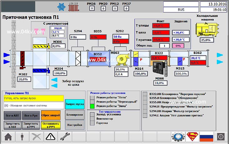
Figure 1. Air handling unit control screen.
The air handling unit is started automatically in response to heating or air supply requests, or in manual mode using the operator panel. At the same time, a prerequisite for the start-up and operation is the absence of active alarm signals from the components of the supply machine, the absence of start-up blocking signals and the absence of the “Manual stop” command.
When the ventilation system is started, the dampers are set to their working position and the electric motors of the pressure fans are switched on. Fan speed is determined automatically depending on the amount of air consumed by the equipment (PID controller based on differential pressure sensor). There is protection in winter from the supply of cold air, during operation the recuperation mode is used.
Maintaining the set temperature is provided by the PID controller.
In semi-automatic mode, part of the automation equipment is turned off. The "Winter" and "Summer" modes are determined by temperature sensors, there is a "Transitional" mode.
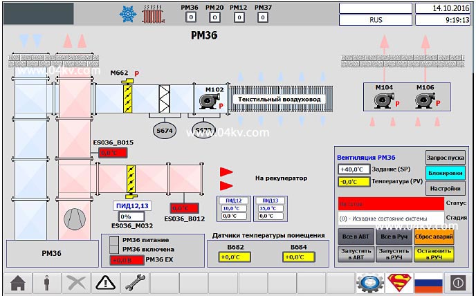
Figure 2. Mnemonic diagram for supply ventilation control.
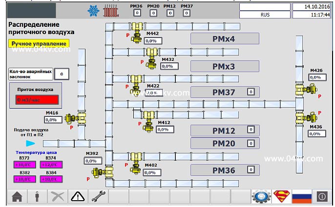
Figure 3. Air distribution damper control screen.
The position setpoint value of each valve can be changed from the operator panel.
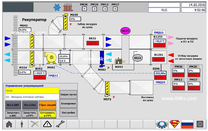
Figure 4. Control screen of the recovery system.
The recuperation system heats the outside (fresh air) to the required temperature and supplies it to the mixing chamber of the air handling units. As a heat source, hot exhaust air taken from the exhaust ducts of the operating equipment is used. Heat transfer is carried out by means of a rotary heat exchanger.
Ventilation control
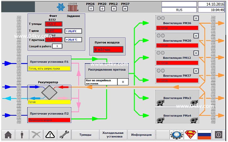
Figure 5. Main screen of the control system.
Allows you to monitor the status of all elements of the ventilation system and activate control screens.
- The top panel consists of the following elements:
- Sign "Sun" - visible if the flag "Summer" is set;
- Sign "Snowflake" - visible if the flag "Winter" is set;
- "Battery" sign - visible if there is a heating request;
- Number of working machine sections;
- Username;
- Operator panel interface language;
- Date;
- Time.
- The bottom panel consists of the following elements:
- Button to go to the main screen;
- Login button for a specific account;
- Logout button;
- Button to go to the screen with the history of emergency messages;
- Button to go to the screen with trends;
- Button for calling the refrigeration unit control screen;
- Information screen call button;
- Button to call the screen with panel settings;
- Button for activating Superman mode. Available only under the Administrators group account.
- Button for switching the interface to Russian;
- The button to end the execution of the running program on the panel.
The automatic control system for the ventilation of the industrial workshop, in addition to automatically maintaining the microclimate in the room and the volume of supplied air, provides constant self-diagnosis of malfunctions of the system components, activation of bypass and emergency operation algorithms to ensure a non-stop production process. For the convenience of maintenance personnel, archives of system messages, a parameter logger, hour meters and automatic notifications of the need for maintenance are provided.
Conclusion.
The developed automatic ventilation control system makes it possible to automatically provide the technological process all year round, maintain the microclimate in the workshop, achieve significant energy savings by optimizing the algorithms for preparing and distributing air.