Water networks
 The details of the wells of the water supply system contain on the diagram the installation points for valves, hydrants, fittings and fittings, and the location of the valves should ensure selective shutdown of emergency sections so as not to disturb the uninterrupted supply of water to other objects. The device of water wells is carried out on water supply networks for inspection and prevention of flange connections and valves, therefore they are also called inspection wells. The size of the working is determined by the dimensions of the equipment installed in it and the convenience of servicing the mechanisms; the section can be rectangular, but more often it is round. The depth of the pipeline affects the bottom mark of the working: this value must be below the freezing level of the soil, but always not less than 1 m from the surface to the top of the pipe.
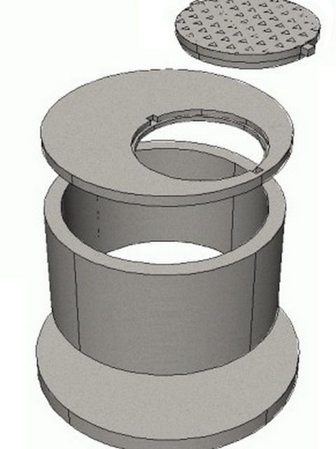
The well is a working chamber buried in the ground with a base and a neck closed by a cast-iron hatch. The entire internal space at the contact with the rock is laid out with bricks or precast concrete, more often in rings. The hatch must have a blind area within a radius of 1 m and rise above the surface to prevent precipitation from entering it.
 When constructing a working in aquifers, all its elements are waterproofed (0.5 m above the mirror) from the bottom to the neck, special attention should be paid to the entry and exit of pipes through the walls of the working chamber. The device of a well with a fire hydrant is practically no different from the manufacture of a viewing one.
To prevent displacement of pipes at socket connections, when they can disperse under the influence of internal pressure in the pipeline, stops in the form of concrete (brick) blocks can be installed inside the well. The same stops are placed directly into the ground on the branches, turns and dead-end branches of the system.
The design of domestic wells is much simpler, which are often reinforced with a simple log cabin and used for water supply of a personal plot, irrigating garden plants and as drinking water.
drop well
There are cases when the flow rate should not be lowered, but increased. To do this, a water seal is installed in the design. A chamber is formed that accumulates water, as a result of which it is possible to create the necessary pressure in order to give the required speed to the flow at the outlet of the water valve. All these values are determined in the project calculations.
There are various configurations for the design of differential wells. Sometimes, to regulate the speed of the water flow, a fast flow is organized using a tray laid with a certain slope.
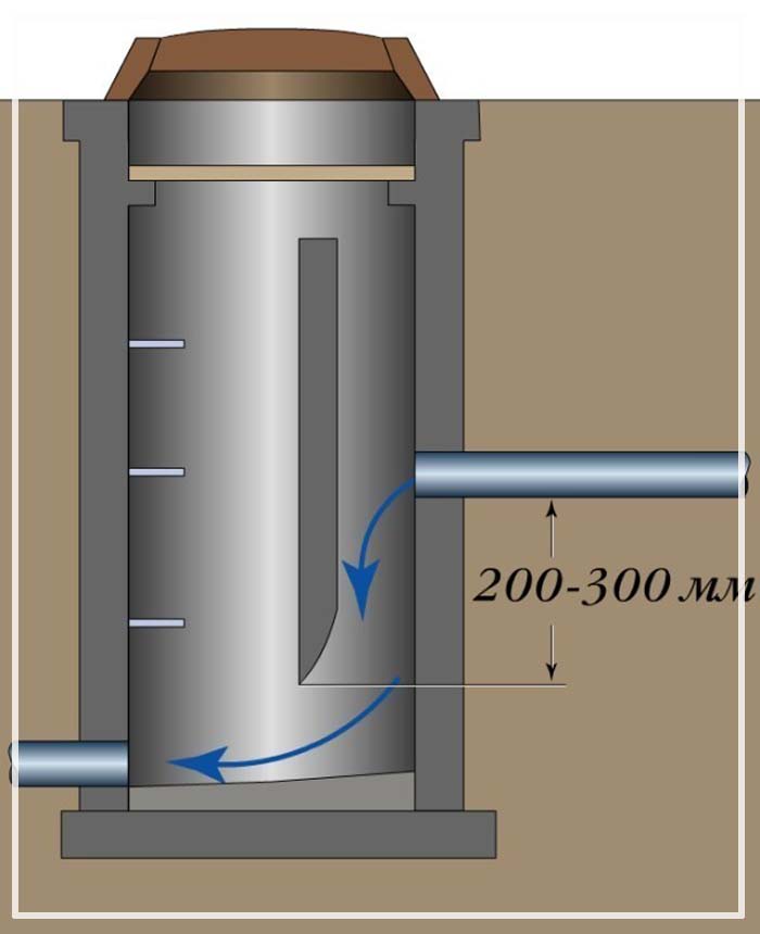
The greater the depth of the absorber well, the stronger the speed reduction effect will be. The pressure of the stream will be extinguished in the water column (pool), into which it strikes from a height. If the pressure needs to be lowered even more, then a retaining wall is built inside the well structure, hitting which the flow loses its speed. Sometimes a sewer pressure absorber is installed after a fast current. It all depends on the specific engineering solution and calculation.
The drawing shows a damper well with a chipper.
This solution is used when you need to further reduce the flow rate:
There are plastic, concrete and brick wells.
In long-distance main pipelines, overflow wells made of concrete are used, but plastic wells are quite suitable for a small private sewer network. Advantages of a plastic damper well:
- light weight;
- facilitated installation process;
- holes for pipelines are provided in the design of the finished product;
- the tightness of the connections of all elements of the system is thought out.
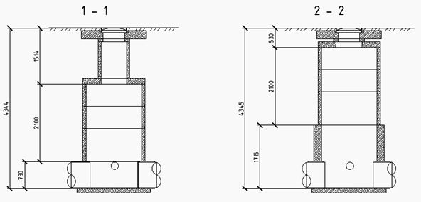
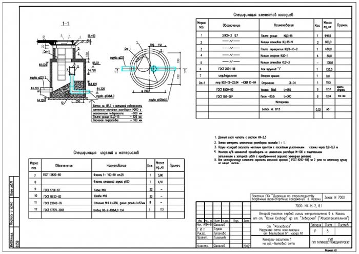
Immersion of a monolithic well Kl-1 by the lowering method. Work production schemes. Section - Water intake facilities.
- Stage I (preparatory) of construction:
- one.Excavation of peaty soils (black peat) to a layer of loam;
- 2. Arrangement of a design embankment for water intake facilities and a pumping station;
- 3. Arrangement of a concrete fore-mine, at the place of technological pits, the fore-mine must be made with the device of expansion joints with separation of blocks with mounting loops;
- II stage of construction:
- 1. Excavation along the perimeter of the knife part of the well;
- 2. Installation of formwork, installation of embedded parts, reinforcing meshes and products;
- 3. Backfilling of the sinuses with crushed stone with layer-by-layer compaction;
- 4. Concreting of the knife part of the well to a height of 3.75m.
- III stage of construction:
- III stage of construction:
- 1. Excavation using an excavator equipped with a grab. The excavation should be carried out evenly over the entire area of the well - from the center of the well (I) to its edges (II), while the surface of the face should have a slope from the knife to the center so that the soil under the weight of the well is evenly squeezed out under the bench of the knife;
- 2. Formed sinuses to fill with clay solution with a density of at least 1.25t/m³;
- 3. Arrangement of auxiliary scaffolding and scaffolding;
- 4. Installation of formwork, installation of embedded parts, reinforcing meshes and products;
- 5. Concreting of the 1st section of the well to a height of 4.00m.
- IV stage of construction:
- 1. Excavation with the help of an excavator equipped with a grab to the design mark of the immersion of the well;
- 2. At the end of the immersion of the well (draft to the mark of the bottom of the knife part -17.30, mark of the upper edge of the III section -1.150m), plug the slot of the outer jacket with cement mortar grade M50 on sulfate-resistant Portland cement grade M300;
- 3. Anchoring of the well to the foreshaft by means of the device of monolithic stops along the perimeter of the well;
- 4. Cleaning the bottom of the well to the bottom of the knife part.
- V stage of construction:
- 1. The device of continuous flooring at the level of the cut-off of the well;
- 2. Installation of a concrete pipe with a funnel for receiving the concrete mixture;
- 3. Device for leveling concrete pad;
- 4. Pumping ground water from the well;
- 5. Device of auxiliary scaffolding at the lower level of the well;
- 6. Device for leveling screed and waterproofing of the bottom of the well;
- 7. Reinforcement and subsequent concreting of the well bottom slab.
Typical technology for waterproofing and protecting concrete structures of receiving wells with a water seal
- When applying concreting:
- For the manufacture of reinforced hydraulic concrete with an accelerated rate of curing, use the additive Dehydrol lux brand 10-2 with a consumption of 4 liters per 1 m3 of concrete mix. Dehydrol lux brand 10-2 additive should be introduced into the concrete truck mixer 5 minutes before the concrete mixture is unloaded.
- When concreting at a negative temperature, an antifreeze additive compatible with Dehydrol should be used Betonoprav lux grade 6. The approximate consumption of Betonoprav lux grade 6 in liters per 1 m3 of concrete mixture is equal to the value of negative temperature (frost) in degrees Celsius.
- Before each concreting, surfaces in contact with the poured concrete mixture (formed adjunctions and especially working joints) must be cleaned of dirt, dust, debris, and also a layer of water (if possible).
- When concreting, the concrete mixture is compacted with the help of vibrators, ensuring the solidity of the concrete and its hermetic adjoining to the walls and previously poured concrete.
- After the concrete mixture with the additive has set, care does not differ from care for normal hardening concrete, taking into account the requirements of SP 70.13330.2012 (updated version of SNiP 3.03.01-87).
- As a rule, at 20°C on the 7th day, concrete gains 100% strength. It is recommended to proceed with further work before the set of high-strength concrete.
- Joints, working seams of concreting (“cold” seams) and other adjunctions, including adjunctions of “new” concrete to “old”, open by cutting along them chisels with a section of 30x30 mm using a wall chaser, “grinder” or in another way.If cramped conditions do not allow cutting a stab with a section of 30x30 mm, then the section of the stab is proportionally increased, for example, up to 40x40 mm. Fill the prepared streaks hermetically with Dehydrol Lux brand 5 "Repair and penetrating waterproofing" flush with the adjacent surface. The consumption is 1.7 kg per 1 dm3 of the streak to be filled or 1.53 kg per linear meter for a streak with a section of 30x30 mm, or 2.72 kg per linear meter for a streak with a cross section of 40x40 mm. joints of prefabricated concrete structures at the stage of installation Dehydrol lux grade 5 with the addition of Dehydrol lux grade 20, as shown in the diagrams.
- Open the joint of concrete with a sleeve for entering communications in the form of a circular streak with a section of 30x30 mm using a wall chaser, grinder or in another way. If cramped conditions do not allow cutting a stab with a section of 30x30 mm, then the section of the stab is proportionally increased, for example, up to 40x40 mm. Fill the prepared streaks hermetically with Dehydrol Lux brand 5 "Repair and penetrating waterproofing" flush with the adjacent surface. The consumption is 1.7 kg per 1 dm3 of the streak to be filled, or 1.53 kg per linear meter for a streak with a section of 30x30 mm, or 2.72 kg per linear meter for a streak with a section of 40x40 mm.
- Clear the joints of the sleeve with communications (pipes, cables) to a depth of at least two times greater than the gap between the sleeve and communications. Typical cleared section: depth 80 mm, width 40 mm. The cleared area in the sleeve around the communications is sequentially hermetically filled with Dehydrol lux grade 7 and Dehydrol lux grade 5. First, apply Dehydrol lux grade 7 inside (consumption 1.5 kg per 1 dm3 of the filled cavity or 2.4 kg per linear meter for a layer of material with a section of 40x40 mm), leaving a groove outside with a depth not less than the size of the gap between the sleeve and communications. Finishing the free groove left outside should be flush with the adjacent surface Dehydrol lux grade 5 (consumption 1.7 kg per 1 dm3 of the filled cavity or 2.72 kg per linear meter for a layer of material with a section of 40x40 mm)
- After embedding, treat the concrete surface with Dehydrol Lux grade 3 at a rate of 1.2 kg/m2.
- Outside the well, treat concrete structures with Contacid grade 3 at a rate of 0.2 l per 1 m2, use a working solution of 1:3.