The main advantages of communication wells
All KKS are divided into light and heavy systems. The light ones are placed under the pedestrian zone, the heavy ones - under the roadway. The communication wells are made of high density polyethylene, and the covers for the device are made of cast iron, concrete or HDPE. Without exception, cable systems have the following advantages:
- resistance to low temperatures;
- tightness of the structure;
- the possibility of installation in difficult conditions;
- excellent strength;
- light weight;
- long service life;
- ease of installation, storage and transportation;
- the ability to connect the model to the sewer of a free configuration.
3. Requirements for the construction of shaft wells
3.3.1. mine wells
designed to receive groundwater from the first free-flow from the surface
aquifer. Such wells are a round or
square shape and consist of a head, a trunk and a water intake.
If it is impossible to maintain this distance, the place
location of water intake facilities in each case is consistent with
Center for State Sanitary and Epidemiological Surveillance.
3.3.2. headroom
(above-ground part of the well) serves to protect the mine from clogging and pollution, and
also for observation, water lifting, water intake and must have at least
0.7 - 0.8 m above the ground.
3.3.3. well head
must have a cover or a reinforced concrete floor with a hatch, also closed
lid. From above, the head is covered with a canopy or placed in a booth.
3.3.5. Shaft (mine)
serves for the passage of water-lifting devices (buckets, pails, scoops and
etc.), as well as in some cases for the placement of water-lifting mechanisms. Walls
the shafts must be tight, well insulating the well from penetration
surface runoff, as well as perched water.
3.3.8. Water intake part
the well serves for the inflow and accumulation of groundwater. It should be buried in
aquifer for better opening of the reservoir and increase in flow rate. For
ensuring a large influx of water into the well, the lower part of its walls may have
holes or set up in the form of a tent.
3.3.9. For a warning
bulging of soil from the bottom of the well by ascending flows of groundwater, the appearance
turbidity in the water and facilitate cleaning at the bottom of the well, a return
filter.
3.3.10. To descend into
the well during repair and cleaning, cast-iron brackets must be embedded in its walls,
which are located in a checkerboard pattern at a distance of 30 cm from each other.
3.3.11. The rise of water from
shaft wells is carried out using various devices and
mechanisms. The most acceptable from a hygienic point of view is
use of pumps of various designs (manual and electric). At
the impossibility of equipping the well with a pump, a gate device is allowed
with one or two handles, gate with a wheel for one or two buckets, "crane"
with a public, firmly attached bucket, etc. The size of the bucket should be approximately
correspond to the volume of the bucket so that the pouring of water from it into the buckets does not
presented difficulties.
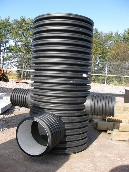
Plastic wells are a modern alternative
A reasonable and practical replacement for stone viewing chambers are polymer counterparts.
Moreover, plastic wells can significantly reduce the amount of earthworks, the construction of sewer wells made of these materials speeds up and simplifies the process of installing drainage systems.
There are rumors about the compressive strength of plastic wells - but they are not confirmed by the facts. This is especially true of the simplest wells for intra-yard networks.
As a rule, there are no such loads that are able to damage the plastic.
Among other things, a concrete well with a diameter of a meter can replace a plastic well, starting from 30 cm in diameter, despite the fact that, despite the difference in size, the maintenance of sewer wells made of polymers will be even simpler than their giant concrete counterparts.
After all, they are produced with releases that clearly comply with the standards of pipes from any material - plastic, cement, asbestos.
Therefore, immediately after installation, such mines can be connected to any within minutes. If plastic pipes are used, then the process will be even faster.
Therefore, before building a sewer well, it is worth weighing the pros and cons, the seeming cheapness of some solutions is deceptive. For a private area where one, two, maximum three wells are equipped, it will be much cheaper to arrange wells made of plastic than trying to save money by using concrete rings. The enormous weight and the need to order heavy equipment will nullify the seeming cheapness of old solutions. And the modest diameter of the plastic well, the speed of installation are not the last arguments.
There are open and closed types. They are used for the purpose of separating sewage effluents, with the help of which heavy fractions and large debris are separated from water. These open-type structures are a reservoir that is assembled from perforated concrete blocks. In them, the liquid goes independently into the ground through special holes. Heavy fractions remain in the mine and are removed using special equipment for further disposal.
Closed-type plants are a special hermetic container that has technological outlets located at different heights. When sewage enters the mine, floating particles are discharged through the upper channels, and sediment layers are discharged through the lower channels.
It is necessary to install the structure in a place where groundwater occurs below the level of the bottom of the station. Additionally, a crushed stone pillow of 0.5 m is poured. The base should rise above the soil at 1 m.
Conclusion
Before you start equipping a sewage network, be sure to read all the provisions of SNiP, start planning, marking, and then choosing the mine that suits you. You will definitely need an estimate for the installation of a sewer well in order to correctly calculate in advance all the costs for arranging the entire backbone network.
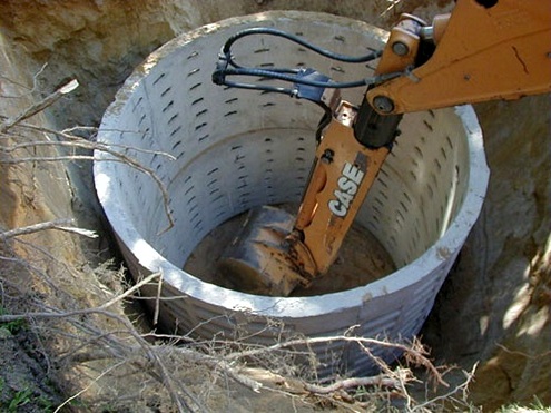
stone wells
After that, the following work is performed for a concrete or reinforced concrete well:
- Foundation preparation. Laying a slab or placing a concrete pad 100 mm thick from concrete M-50
- Arrangement of a tray of the desired shape made of M-100 concrete with steel mesh reinforcement
- Concrete and bitumen sealing of pipe ends
- Bitumen insulation of the inner surface of concrete rings
- Rings of sewer wells are installed (carried out after the curing of the concrete of the tray, 2-3 days after laying) and the floor slab on the M-50 mortar
- Grouting with cement mortar the joints between the prefabricated parts of the well
- Waterproofing joints with bitumen
- Finishing the tray with cement plaster, followed by ironing
- Arrangement at the entry points of pipes of a clay lock with a width of 300 mm and a height of 600 mm more than the outer diameter of the pipes
- Well testing (carried out during the day by filling with water to the upper edge, with the installation of temporary plugs on the pipes). Considered successful if no visible leaks are found
- External backfilling of the walls of the well, followed by tamping
- The device of a concrete blind area 1.5 m wide around the neck of the well
- Insulation of all remaining joints with hot bitumen
Similarly, brick sewer wells are installed, but here, instead of installing prefabricated elements, masonry is made.
Waterproofing is done in exactly the same way.
Thus, the installation of wells made of stone materials is carried out for all types of sewerage: domestic, storm or drainage.
However, in the case of a storm well, lattice hatches can be installed on the well, which simultaneously perform the function of a catchment area.
For drainage - the well itself can be an element of drainage, through special holes in the walls, but this design requires a special calculation.
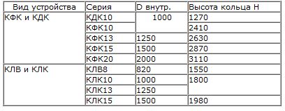
At the same time, there are slight differences in the components that the series defines: sewer wells KFK and KDK - for domestic wastewater, KLV and KLK - for storm water, KDV and KDN - for drainage.
The table of sewer wells by standard sizes is as follows:
The process for differential wells looks a little more complicated due to their more complex configuration.
Here, depending on the specific design, in addition to the tray device, in some cases it is necessary:
- Riser installation
- Water breaking equipment
- Installation of a water barrier wall
- Create a practice profile
- Pit device
The very installation of the body of the mine, base and ceiling is carried out according to the same rules.
The only exception concerns a drop well with a riser - at its base it is supposed to lay a metal plate that prevents the destruction of the concrete part of the structure.
It looks like this:
- Riser
- water cushion
- Metal plate at the base of the pillow
- Riser intake funnel
The intake funnel is designed to compensate for the rarefaction that can be created in the riser due to the rapid movement of wastewater.
It is necessary to create differential sewer wells with your own hands using a practical profile only in exceptional cases - a similar design is provided for pipelines with a diameter of 600 mm and a drop height of up to 3 m.
Similar pipe diameters are not used in individual drainage systems. But other types of wells can be used in local sewage with success.
In accordance with the requirements of SNiP, sewer overflow wells are installed:
- If necessary, reduce the depth of the pipeline
- At intersections with other underground utilities
- For flow control
- In the last flooded well before the discharge of waste into the reservoir
Typical cases when the installation of a drop well in a suburban area is advisable:
The meaning of such a drop is that due to the creation of a large slope in a short section of the system, the drains begin to move much faster, not having time to cling to the inner walls of the pipe.
Distance between manholes according to SNiP
Manholes should be installed in such situations:
- in the presence of an extended pipeline running in a straight line;
- if there are turns or bends in the pipeline, as well as when the diameter of the pipes changes;
- in the presence of branches of the structure.
Determines the distance between the SNiP sewer wells, and according to it, the following rules must be followed:
- with a pipe diameter of 150 mm, wells are installed every 35 meters;
- 200-450 mm - 50 m;
- 500-600 mm - 75 m.
As a rule, when arranging private sewer systems, pipes with a diameter of 100 mm are used. When using them, the distance between sewer wells is defined by SNiP as 15 m. In the event that the sewer does not have bends, branches, and the diameter of the pipeline does not change throughout its length, then the distance can be increased to 50 m.
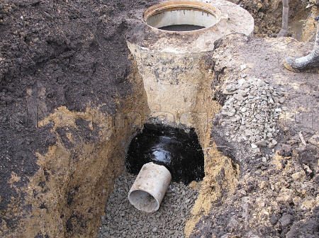
How is the installation
Installation of a cable well takes place in several stages:
-
First, the pit is prepared.
It should exceed the dimensions of the well by about 200 mm. -
Next, a concrete pillow is made.
Its dimensions depend on the dimensions of the cable well. If the groundwater level is higher than the bottom of the well, the bulk soil should be carefully compacted.At the end, an anchor is made of concrete, which will prevent the well from floating up. The anchor is produced using a formwork with a round or rectangular section. If a well is installed where the transport passes, a 200 mm reinforced slab is poured, which will make it possible to evenly distribute the load. -
Installation of the well itself
It is carried out using special equipment, but it can also be done manually. The structure is attached to anchor bolts, cables. -
Conducting backfilling.
The backfill is a mixture made of sand and cement in a ratio of 1/5. It should be carefully compacted every 20 cm.
The connection to the conduit system can be made in various ways:
- using a slip-on coupling with sealing rings;
- with the help of a compression coupling;
- using a sliding sleeve with sealing rings.
Communication wells are actively used in buildings of various types. They reliably protect cables from damage and serve for a long time. Wells of the indicated type are made from various materials, but plastic is most often used. Devices should be built in accordance with a number of technical norms and rules. If you use high-quality materials, do not violate the technology and choose the right place, the communication well will serve the house for a long period of time.
The device of sewer wells made of concrete
In the case of a concrete or reinforced concrete structure, the arrangement of the sewer well will look like this:
- first, the base is prepared, for which a monolithic slab or a 100 mm concrete pad is used;
- further, trays are installed in sewer wells, which must be reinforced with a metal mesh;
- pipe ends are sealed with concrete and bitumen;
- the inner surface of the concrete rings must be insulated with bitumen;
- when the tray hardens enough, it is possible to lay the rings of the well itself into it and mount the floor slab, for which cement mortar is used;
- all seams between structural elements must be treated with a solution;
- after grouting with concrete, it is necessary to provide the seams with good waterproofing;
- the tray is treated with cement plaster;
- at the pipe connection points, a clay lock is arranged, which should be 300 mm wider than the outer diameter of the pipeline and 600 mm higher;
- one of the final steps is to check the design for operability, for which the entire system is completely filled with water. If no leaks appear after a day, then the system is functioning normally;
- then the walls of the well are filled up, and all this is compacted;
- a blind area of 1.5 meters wide is installed around the well;
- all visible seams are treated with bitumen.

The device of a sewer well made of concrete rings, described above, is no different from the arrangement of a brick structure, with the only difference being that in the latter, concreting is replaced by brickwork. The rest of the workflow will look the same.
In addition to the tray, one or more conditions may be required to equip the overflow well:
- riser installation;
- water tower installation;
- arrangement of a water-breaking element;
- creation of a practical profile;
- pit arrangement.
Thus, the composition of the differential well includes:
- riser;
- water pillow;
- metal plate at the base;
- intake funnel.
According to regulatory enactments, the device of a well for sewerage is justified in such situations:
- if the pipeline needs to be laid at a shallower depth;
- if the main highway crosses other communication networks located underground;
- if necessary, adjust the speed of movement of effluents;
- in the last flooded well, immediately before the discharge of wastewater into the water intake.
In addition to the reasons described in SNiP, there are others that necessitate the installation of a differential sewer well on the site:
- if there is a large difference in heights between the optimal depth of the sewer at the site and the level of the wastewater discharge point into the receiver (this option is often justified, since laying the pipeline at a shallower depth allows you to perform less work);
- in the presence of engineering networks located in the underground space and crossing the sewer system;
- if there is a need to control the rate of movement of wastewater in the system. Too high speed has a bad effect on the self-cleaning of the system from deposits on the walls, as well as too low speed - in this case, deposits will accumulate too quickly, and the use of fast current is required to eliminate them. Its meaning is to increase the fluid flow rate in a small section of the pipeline.
Sealed cesspool
It is possible to fully meet the requirements for sewer wells only during the construction of a sealed sewer well
. This method does not harm the environment, the volume of effluents can be increased.
This method is recommended in areas with moderate wastewater output. For example, a family of 4 can produce about 600 liters of effluent per day, accounting for 150 liters per person. Therefore, it is better with a margin in volume. It is worth remembering that its depth should not be more than 3 meters, otherwise the pipe of the sewage truck will not reach the bottom.
The requirements and distances between objects according to SNIP for a sealed well are similar to the above requirements for a pit without a bottom.
The accumulated sewage is taken 1-2 times a month by a sewage truck.
The construction of sealed sewer wells is possible using various materials.
The most popular today are:
- Reinforced concrete rings.
- Brick.
- polymer tanks.
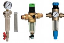
Septic tank with filter well
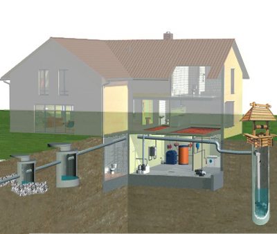
This option is already an engineering structure, where the effluents undergo real treatment and then drain into the soil. The level of purification (clarification) of wastewater is up to 80%
.
The principle of operation of this design is as follows: drains from the dwelling fall into a sealed sewer well. Here, solid particles settle to the bottom, and clarified water flows into the drainage well, where it is further cleaned and released into the ground.
In order to improve the quality of cleaning, 2-3 drainage wells can be used (a series of sewer wells).
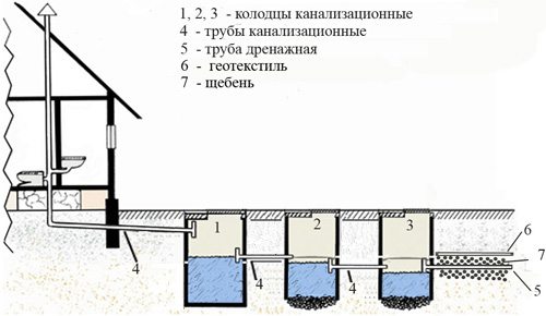
It is built on the principle of a sealed drain pit (see above). A drainage well is built according to the same principle, only without a bottom and not sealed. Moreover, the lower edge of the walls of the drainage well is perforated for better drainage of water into the ground.

We dig a hole with a margin of 40 cm in depth. We lay 20 cm of sand on the bottom, 20 cm of gravel on it. This is an additional filtering structure. About a meter from the bottom of the well walls we make perforated. We also sprinkle the outer wall of the perforated well with 20 cm gravel to prevent clogging of the holes with soil.
SNIP regulates such sewer wells in the same way as with drain pits. All distances are the same.
The main types of wells
According to the field of application, wells are divided into several main types: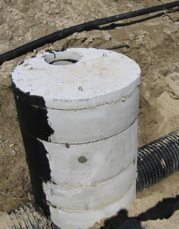
- For regular inspection or viewing - structures are located in places of stop valves and are intended for monitoring and servicing sewer systems.
- Rotary - a kind of manholes. Are arranged at the bending points of the pipeline. The main purpose of such structures is quick access to the bend (elbow) of the pipe in order to clean it from contamination.
- Filtration - special structures devoid of tightness (having a perforated bottom).Serve for accumulation of not strongly polluted runoff waters with their subsequent filtration in soil. It is the ideal solution for draining showers or house drainage systems. At the bottom of the well, a filter of fine gravel and sand is arranged (sometimes the mine is covered with the same material). The thickness of the filter is not less than 40-50 centimeters.
- Gradient - structures designed to dampen or increase the flow rate. Are established in places of sharp deepening of the pipeline or in points of accession to the highway of deep-seated collectors. The design is based on a vertical branch pipe (drop - a part in the form of a straight cross and a knee). The well itself is arranged as a multi-stage structure or has the shape of a classic mine.
- Serving to store water or storage - sealed wells, the liquid from which is pumped out using a pump or flows through a signal pipe into the nearest ravine. To clean such a well, the owners often involve vacuum cleaners. The frequency of cleaning directly depends on the capacity of the well. The more capacious it is, the less often you will have to resort to pumping out the liquid. The average height of the well is two meters.
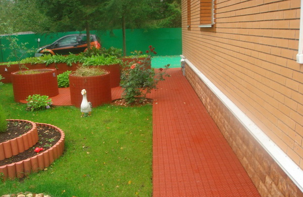
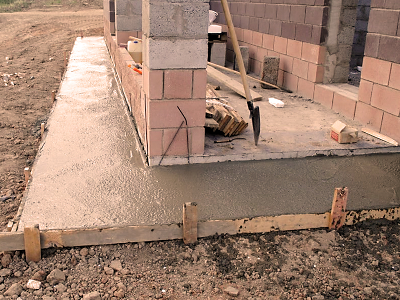
The general concept of the blind area and its main characteristics
The blind area is a protective, waterproof strip, which is located horizontally around the perimeter of the entire building. For a more detailed study of its appearance, you can look at the site "blanket area photo". Its ideal width is approximately 1-2 meters and is closely adjacent to the walls of the foundation or basement of the house.
The blind area protects the house from underground, ground, storm and melt water. For its laying, various materials are used: a blind area made of crushed stone, concrete, etc. Sometimes it can also have a decorative function, and is also a footpath.
The design of the blind area consists of two layers: the underlying layer and the coating. Sand, clay or gravel is used as the underlying layer, and the coating is made of waterproof material (concrete, asphalt, paving slabs, etc.)
Other regulations
Conclusion
All owners of country houses, sooner or later, are taken for the arrangement of life support systems. After all, a comfortable country life implies the supply of residential buildings with everything necessary - heat, drinking water and, of course, the possibility of drainage or sewerage.
Sewerage of an autonomous type is a rather complex engineering system, the installation of which requires certain plumbing and construction skills.
. One of the most important elements of any autonomous sewage system is a special well. Moreover, the sewerage needs the arrangement of several wells at once - rotary, inspection, and also receiving household waste and rainwater. Understanding the device and varieties of such wells will be useful for any zealous owner.
What wells are needed
- Storage tanks are required exclusively for the arrangement of autonomous sewer systems.
- Floating structures are more often used when connecting home sewage to the central city highway.
- Filtration structures can be used for wastewater with clean water that does not contain impurities harmful to the environment. For example, for arranging a shower, a drain from a shower or bath. Water from washing machines and dishwashers containing aggressive detergents must not be filtered into the ground!
- Rotary and viewing structures are arranged both in autonomous systems and on pipelines connected to a public highway.
SNiP requirements for the dimensions of the blind area in terms of and its thickness
The width of the blind area around the house is determined depending on the type of subsidence of the soil. All clay (loess) soils are subsiding to varying degrees. You can determine the type of soil in the laboratory. SNiP 2.02.01–83 approves two types of soils:
“Type I - soil conditions in which there is no subsidence due to the own weight of the soil or does not exceed 5 cm; drawdown is possible mainly from an external load.
Type II - soil conditions in which, in addition to subsidence of soils from external load, their subsidence from their own weight is possible and its value exceeds 5 cm.
The same document determines the width of the blind area according to GOST. For soils of the first type, it should not be less than 1.5 m, and for soils of the second type, the width of the blind area should not be less than 2 m.
When building on subsiding soils, all measures must be taken to ensure that the foundation passes through the subsiding layer, plus the use of special building technologies.
With normally bearing soils, regulatory documents determine the minimum width of the blind area at 0.8–1.0 m. At the same time, its width must necessarily exceed the overhang of the roof above the walls by 20–30 cm.
The thickness (height) of the blind area is to a lesser extent normalized by SNiP. According to regulatory documents, after sampling the soil and vegetation layer over the entire width of the blind area, a base of clay, sand or crushed stone, at least 15 cm thick, is arranged and rammed. Next, hydro- and heat-insulating layers are laid.
The height of the blind area around the house (the mark of the upper protective layer on the outer edge of the blind area) should rise above the “0” mark by at least 5 cm.
If the blind area according to the plan is pedestrian, then the requirements for it from regulatory documents increase in width and strength.
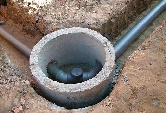
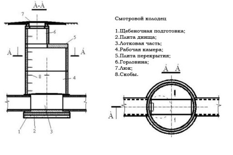
The internal structure of a typical sewer well
Functionally, well structures differ, but they all have:
- lid or neck on top;
- shaft and working chamber in the middle;
- bottom-support at the very bottom.
Elements can be of different shapes and sizes. Everything in this matter depends on the purpose of the well. In the filtration bottom, it is made “leaky” - with a drainage cushion, and the rest of the types are made in a sealed design with a solid bottom. Mines also have the most diverse device and a different number of pipe entries.
The sewer system gets clogged sooner or later. It is with the help of wells that cleaning is carried out. Previously, a plumber went down to do this, but in the last decade, silo pumps and high-pressure installations have become increasingly used. As a result, well shafts no longer need to be made large, under the dimensions of a descending person. Enough narrow chambers into which you can squeeze the hose of the sewage equipment.
Now it is mainly to install sewer wells of small size made of plastic. It's cheaper, more practical and faster. Similar plastic products are produced in the factory. The model range is wide and allows you to choose an option for installation in any sewage system in terms of power and purpose.
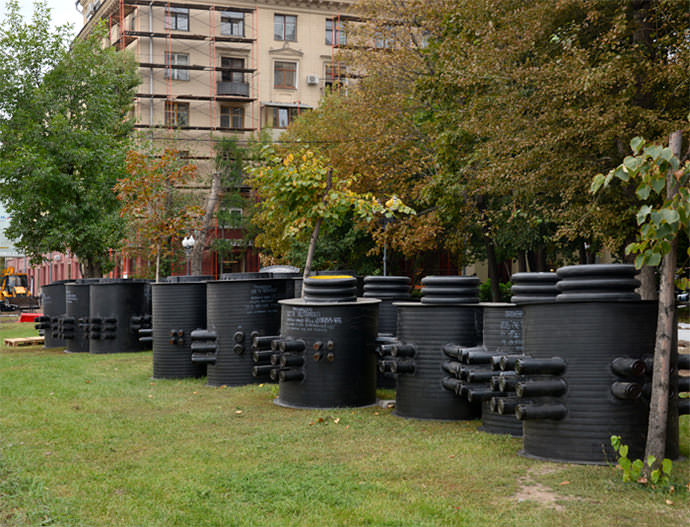
The main types of cable wells
Plastic cable manholes are used to install, pull, repair and test communication cables. Installation of wells is carried out in non-aggressive soils in relation to concrete.
The main types of cable communication wells are KKS-2 and KKS-5. They have an octagonal shape and include two halves - the upper one, which has an upper ceiling and half of the side walls, the lower one - half of the side walls and the bottom. Also, cable wells in their overlap have a hole equipped with an entrance hatch.
Shallow penetration cable systems are also on the market. They can be located on sidewalks, lawns and under the road. Unlike other types of wells, the coupling in shallow penetration devices is assembled outside, and not in the mine. Then it, along with the cables, is lowered to the well bottom. There are no seams on the presented structure, so the impact of groundwater will not damage the system. In this regard, the period of use of the shallow penetration system is much longer.
Regardless of the type, all communication wells are made of M200 concrete. They are designed to withstand the load of the roadway. There is a reinforced ring at the top of the well. At the bottom there is a special pit for water drainage. Another of the elements of the well is worth noting ruffs that allow fixing brackets for equipment and cables, and earrings used to fix the unit during the cable.
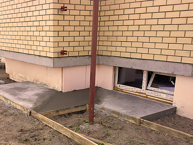
Simple technologies for self-filling the blind area with the creation of slopes
There are several ways to fill the blind area with a slope. The easiest way is to build and fill a horizontal blind area. After the construction of the pit for the blind area, the leveling layer is poured and rammed. Then the waterproofing of the junction and the entire blind area is installed, flooring or insulation is laid. Next, the reinforcing mesh is laid and the main (80%) concrete layer is poured. Concrete, when leveling and tamping, will itself lie horizontally around the entire perimeter of the house. After hardening of the main layer, it is possible to mark the transverse slope with the help of special rails nailed to the formwork.
Sectional concrete placement
The rest of the concrete is made thicker and laid out in sections of the blind area with leveling along the rails.
You can make the slope of the blind area around the house in another way - set it when filling and ramming the very first leveling layer. Closer to the walls of the foundation (basement), you need to pour more material.
Installation of gutters and formation of a blind area slope on a leveling layer of crushed stone
The slope is best controlled with a level or level. After the installation of the waterproofing and heat-insulating layers, the slope of the blind area of the building will be preserved. Filling must be done in an even layer in thickness. When hardening concrete, it is necessary to make the surface finish the rule and control the resulting transverse slope.
Filling the blind area with a pre-created slope
SNiP regulates the quality of concrete for the construction of a blind area. In terms of frost resistance, road concrete is used for these works. At the same time, the brand of concrete for the blind area should not be lower than M 200.
conclusions
The general requirements of SNiP on the need to build a blind area for any house are outlined. The dimensions of the blind area according to SNiP for various underlying soils are briefly considered. The basic requirements of SNiP for materials for the manufacture of the blind area and the slope of the blind area around the house are given. Recommendations are given for pouring the blind area with the creation of slopes.
Finally
Wells can be equipped with filters and pumps for supplying water to the house, but in this case you will have to worry about additional insulation, especially at the head.
The device of sewer wells depends on their purpose, and the required number on the design of the system - its complexity, the presence of turns and drops when laying communications, length and other features. Having understood the purpose of various types of structures, it will be easier to design the sewerage of a private house or cottage, to ensure its maximum efficiency.
Where and how sewer wells should be installed SNIP regulates specifically and accurately
It is also important to take into account the Building Norms and Rules because the inspecting authorities necessarily check the structures for compliance with the requirements, and if violations are found, they can issue an order to make changes to the sewerage device, which will require additional costs, and the construction time will increase significantly
Manholes
Such structures are necessary for any sewer system, regardless of its degree of complexity. Wells provide the ability to control the operation of the system and are used for its maintenance (repair, cleaning, flushing, etc.).Depending on where the observation structures are located, there are several types of them:
Drop wells
Drop wells are used to change the flow rate or the depth of pipelines. They are also used when it is necessary to bypass the sewer line of any obstacle (another pipeline, etc.). In general, such structures are a vertical shaft (reservoir) with inlet and outlet pipes. Depending on the purpose, it may be necessary to install this type of sewer wells with additional devices, for example, with steps that dampen the flow rate.
There are the following types of overflow wells:
- classic well design (drainage flow through the top pipe, discharge through the bottom pipe),
- models of wells with baffle and drain wall surfaces to reduce the flow rate,
- channels with a significant slope, capable, on the contrary, of “dispersing” the flow, increasing its speed,
- complex structures of multi-stage drops.
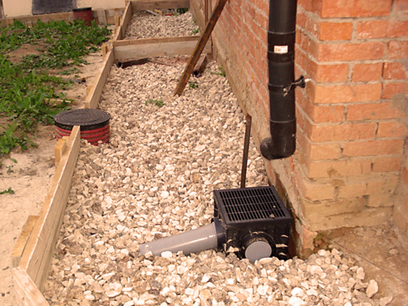
Filtration wells
Models of wells of this type are used in sewerage systems to provide soil post-treatment of effluents partially clarified in the septic tank and to drain the liquid component of the septic tank into the ground. Structurally, the filtration well differs from the others in the absence of a sealed bottom (instead of it, gravel or other filter material is backfilled). There are also options for wells with holes in the walls of the tank. Through such holes, the liquid also goes into the soil, and for its additional cleaning, filter material is also backfilled from the outside of the well at the stage of its installation.
storage wells
The principle of operation of the storage sewer well is the same as that of the one - it is a place for collecting wastewater
When organizing the drive, it is important to ensure its tightness and to provide for the possibility of the access of a vacuum truck to pump out the contents.