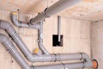
Types of pumping equipment for sewage pumping stations
The main and most important element of any sewage pumping station is a pump, whose tasks include pumping out domestic and industrial wastewater, sludge and liquid media coming from storm sewers. The main types of pumps that are used to equip the sewage pumping station are:
- submersible type devices;
- console pumps;
- self-priming pumping equipment.
Submersible pumping equipment, related to pressure-type devices, is constantly in the liquid medium pumped by it during operation, therefore the body of devices of this type is made of materials that are resistant to the aggressive effects of substances contained in wastewater.
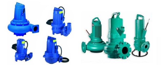
Submersible pumps for KNS
Among the advantages of submersible pumping equipment used to equip the sewage pumping station, the following can be distinguished:
- no need for a specially designated place for installation, since such equipment is located in the medium it pumps;
- high reliability;
- ease of use;
- no need for frequent maintenance;
- the ability to function effectively even at low temperatures;
- spontaneous cooling of the internal elements of the equipment, carried out by the liquid medium pumped by it;
- versatility, which lies in the fact that pumps of this type can be installed on the surface of the earth.
Sewage pumping stations based on submersible pumps are the most popular and simple in design.
With the help of cantilever pumps located on the surface of the earth, maintenance of industrial sewage pumping stations is carried out. To install such pumping equipment, it is necessary to prepare a separate concrete platform and properly connect pipes to it, so it is best to trust the implementation of such a responsible procedure to qualified specialists. The advantages of console-type pumping equipment include:
- high reliability;
- ease of maintenance and repair (since the pump is located on the surface of the earth);
- the possibility of changing the performance of the device, which is carried out by replacing the electric motor and other structural elements.
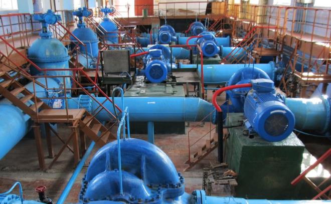
Industrial sewage pumping station based on cantilever pumps
Surface self-priming pumps, which can be used for pumping even heavily polluted media, are used to service sewage pumping stations of industrial and municipal enterprises. If we talk about the advantages of pumps of this type, then this should include:
- ease of maintenance, which is provided by a retractable design;
- the possibility of pumping wastewater containing solids in its composition;
- the ability to work even at low temperatures when equipped with a special heating element;
- maximum tightness of the body, which is provided by a double mechanical seal;
- ease of installation and dismantling.
Typical design of a pumping station TP 902-1-53MK
Consider, as an example, a typical design of a pumping station TP 902-1-53MK.
Effluent supply for treatment from 110 to 480 m3/day.
The pressure in the supply manifold is 10-40 m.
The ground part of the project is not provided. The underground part is a reinforced concrete tank of circular cross section, installed vertically, with a diameter of 2 meters, a depth of 1.5 meters. For the manufacture of the tank, reinforced concrete is used, the upper part is assembled from prefabricated rings. All reinforced concrete elements, both monolithic and prefabricated, are made of concrete grades B4 (waterproof) and Mrz50 (frost-resistant). For complete waterproofing, the inner walls and bottom are plastered with cement mortar.
Wall surfaces, the bottom of the receiving tank and equipment are cleaned from sediment with a jet of water under pressure.For this, a supply of clean water is provided, the installation of a watering tap, to which a rubber hose with a hose is connected.
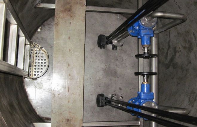
In order to ensure the possibility of carrying out inspections or repairs of the receiving tank, a valve is provided on the supply line that shuts off the flow of effluents into the tank.
To separate large inclusions from the drains, a basket-shaped lattice filter is installed on the supply line. Every day, the basket is lifted to the top for cleaning, the sediment is reloaded into a sealed container and taken to a landfill.
The capacity of the receiving tank is 4.2 m3. Such a volume of liquid can be pumped by one pump in 12 - 16 minutes. The bottom of the receiving tank is made with a slope of 0.1 in the direction of the pumping station, equipped with pumping units 2.5ETsK-16-6. These models of submersible dynamic pumps are specially designed for pumping wastewater. Pumps are installed in the well. When using TsMK pumps, guides are mounted along the walls of the well, while a device is installed on the discharge pipe for automatic docking of pumps with pipelines when the pumps are lowered along the guides into the well. The ECC pump is connected to the pressure pipeline using a flexible hose. These types of connections allow maintenance or repair of pumps to be carried out on the surface, without descending into the well.
In the discharge pipeline of each pump there is a check valve, manually operated gate valves. All valves are located in a separate well and are closed only during repair and maintenance of the pumping station.
The pumps are installed under the bay. The operation cycle is automated, the pumping units are switched on or off when the maximum or minimum level of effluents in the receiving tank is reached. In case of emergency shutdown of the main pump, when the maximum possible level of wastewater in the receiving tank is exceeded, the backup pump is automatically connected.
The set of the pumping station includes SUNO control stations designed for automatic control of pumps.
To ensure natural ventilation, the system is equipped with a pipe, the height of which is several meters.
Regardless of the depth of the inlet collector pipelines and the type of soil, the installation of the pumping station is carried out in an open way.
Typical design of a high capacity pumping station
The project involves the construction of a pumping station with a capacity of 100 - 160 thousand m3 / day. Head 19.5 - 32.7 m. The station is equipped with 5 pumps SDV 2700-26.5-U3, three of which are in operation, two are in reserve. The pumps are switched on automatically when the liquid reaches a predetermined level.
The pumping station is built in the form of a round shaft. The inner diameter of the shaft is 24 meters.
The above-ground part - the building is constructed of reinforced concrete panels or bricks, size 18 × 24 meters.
In the underground part there are: a receiving tank, filter grates equipped with a mechanized rake, a pipeline room, crushers for crushing large waste, a pump room and a room for electric motors. It is planned to use the project at a depth of the supply pipeline of 4, 5, 7 meters.
The useful capacity of the receiving tank is 450 m3. Such a volume of liquid can be pumped out with one pump in 7.5 - 15 minutes. The receiving tank is divided into two parts. The dividing wall is equipped with a shield gate blocking the overflow of liquid between the parts of the tank during repair work or cleaning. The slope of the tank bottom is 0.1 in the direction of the inlet funnels. For flushing the tank in the upper floor, 4 hatches are equipped, 2 for each of the parts. The diameter of hatches is 700 mm. There are also two watering taps equipped with hoses and hoses.For agitation of the sediment, the open ends of the pipes at the suction funnels are used.
In each of the drainage pits, vertical fecal pumps SDV 80/18 are mounted (2 for each pit, one pumping unit is working, the other is standby). A pipeline (150 mm) is laid between the pits. The drainage pumps are connected automatically upon reaching the highest water level in the pits.
K90/55 pumps (working and standby) supply industrial (technical) water and are located in the pipeline room.
Household and drinking water supply comes from a centralized city network, two drinking water inlets with a diameter of 100 mm are provided. Internal distribution of utility and drinking water provides supply to all sanitary devices.
For industrial purposes, water is used to cool oil in electric motor baths, lubricate bearing shells on pumping units SDV 2700 / 26.5-U3, stuffing box seals, grid bearings. A special tank is installed in the pipeline room to break the jet.
Periodic replacement of oil in the baths of electric motors is carried out through the oil pipeline system. The system includes clean and used oil tanks, pipelines for supplying fresh and used oil, as well as two gear pumps.
All rooms are equipped with ventilation systems. In the grating room and the receiving tank, ten times air exchange is carried out hourly, and in the rooms of the electric motors hall, the pumping hall and the pipelines room - a single air exchange per hour.
Pumping station heating is usually designed according to regional climatic conditions.
Installation and Maintenance Recommendations
In order to carry out the installation of the sewage pumping station, it is necessary to first prepare a pit to accommodate the storage tank of the station. The depth of the prepared pit should be such that the neck of the storage tank protrudes 1 meter above the ground. When preparing the pit, it should also be borne in mind that at its bottom it is necessary to equip a sand cushion 1.5 meters thick. After preparing the pit, a storage tank is placed in it, to which all the necessary pipes are connected. The final procedure of this stage of the installation of the sewage pumping station is backfilling the pit with sand and its layer-by-layer compaction.
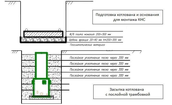
Installation of sewage pumping station in the pit
Further installation of the KNS consists in adjusting the stroke of the floats, which should be located in the tank at certain levels. So, the first (lowest) float is installed in the tank at a level of 0.15–0.3 m from its bottom. The remaining floats, if the KNS device provides for their presence, are installed in containers with a step of 1.5 meters. You can see how the floats should be located in the KNS tank using photos that are easy to find on the Internet.
Level control is carried out using float sensors, which provide timely start and stop of pumps, as well as signaling emergency levels
After the entire structure of the SPS is assembled, the station is connected to the power supply, for which well-insulated cables are used. The test run of the station, the purpose of which is to check the performance of all its elements, is carried out using clean water coming from the water supply system or storage tank.
Both domestic and industrial sewage pumping stations need regular maintenance to maintain efficiency and extend the life of the equipment in use. Maintenance involves the following procedures.
First, the equipment is inspected and the condition of the pumps, the elements of the shut-off valves is checked, the parameter values \u200b\u200bare checked, which are reflected in the KNS control panel.If during operation the pumping equipment makes a lot of noise and vibrates, it is removed, inspected, cleaned and washed.
To clean and flush the pumping equipment, as well as the station body, brushes and plain water are used, while no detergents are used.
When flushing the sewage system using water supplied from a hose, it is important to ensure that no liquid enters the control panel and pressure gauges.
After dismantling the pumping equipment for the purpose of checking, cleaning and flushing, reinstallation should be carried out in such a way that all devices are securely fixed on the automatic pipe coupling.
The maintenance of sewage pumping stations also includes checking the traps that protect the pumping devices from getting into their interior large debris.
Routine maintenance of the station, which is carried out as planned, involves the replacement of worn parts, as well as checking and tightening all fasteners threaded elements.
General information
Depending on the complexity of the design and operational characteristics, sewage pumping stations can be divided into three main categories: simple, medium complexity and complex. It does not make sense to use complex sewage pumping stations for a private house, since such expensive installations are characterized by high productivity, significantly exceeding the volume of wastewater accumulating in a private building. SPS of a complex category are equipped with industrial enterprises, in the course of which a large amount of wastewater is generated.
For servicing private houses, it is advisable to use household sewage pumping stations, which are distinguished by their compact dimensions and affordable cost. When choosing a specific modification of the sewage pumping station for a house, the estimated volume of wastewater, the degree of contamination, as well as the type of pollution that are present in such waters are taken into account.
In addition, it is necessary to take into account the features of the relief of the site where the station will be installed, as well as the depth of the sewer pipes.
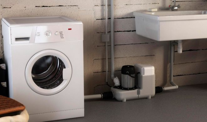
Household mini KNS
How KNS works
The CNS has a fairly simple principle of operation.
- Waste water from the sewer system enters the receiving part of the installation, from where it is pumped into the pressure pipeline by a pump.
- Through the pressure pipeline, wastewater is transported to the distribution chamber, from where it is then pumped to the treatment plant system or to the central sewer.
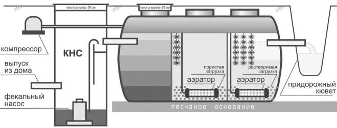
Scheme of sewage treatment of a private house using SPS
In order to prevent wastewater from returning to the pump through the pipeline, the sewage pumping station is equipped with a check valve. In the event that the volume of wastewater in the sewer pipeline increases, an additional pump is switched on at the station. If the main and additional pumps for the sewage pumping station cannot cope with pumping the volume of wastewater, then the device automatically turns on, signaling an emergency situation.
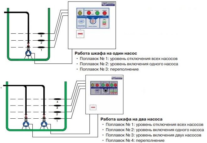
The principle of operation of the SPS for industrial use provides for automatic control of such installations, which is provided by float-type sensors installed at different levels of the station's receiving tank. SPS equipped with such sensors operates according to the following principle.
- When the level of effluents entering the tank reaches the level of the lowest sensor, the pumping equipment remains turned off.
- When the tank is filled with wastewater to the level of the second sensor, the pump automatically turns on and starts pumping wastewater.
- If the tank is filled with wastewater to the level of the third sensor, then the backup pump is turned on.
- When the tank is filled to the fourth (uppermost) sensor, a signal is triggered, indicating that both pumps involved in the sewage pumping station cannot cope with the volume of wastewater.
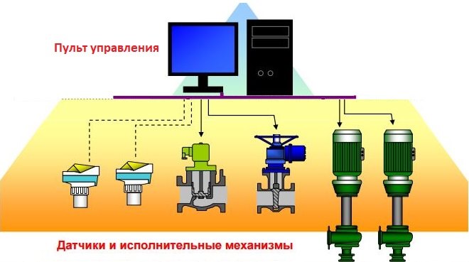
Scheme of automatic control of the work of the sewage pumping station
After the level of wastewater pumped out of the tank drops to the level of the location of the lowest sensor, the system automatically turns off the pumping equipment. The next time the system is turned on for pumping wastewater from the tank, a backup pump is activated, which allows both pumping devices to be operated in a gentle mode. The operation of the station can also be switched to manual control mode, which is necessary in cases where the maintenance of the sewage pumping station or its repair is carried out.
Typical design of a sewer pumping station TP 902-1-70-83 NK
The depth of the input manifold is from 4 to 7 m.
The number of pumping units is three (including one standby).
Brands of pumping units - SD 100/40, SD 160/45, FG 144/46, FG 144/10.5 or FG 450/57.
The inlet manifold passes through the shut-off chamber, in which the shutters are located, as well as the emergency release device.
The underground part of the structure is made of reinforced concrete. It is a well of circular cross section. The ground part is built of brick and has a rectangular shape.
The tank capacity is 45 m3. Such a volume of liquid can be pumped in 12 minutes when using the SD 100/40 pump unit, in 8 minutes with the SD 160/45 pump, or in 5 minutes with the FG 450/57 pump. The bottom of the receiving tank is made with a slope of 0.1 in the direction of the pit, in which the suction pipes are mounted.
To separate large suspended pollutants from wastewater, the system is equipped with filter grids. 2 RD-600 grate-crushers or KRD-40 grate-crushers are installed in the room. In this case, one of the gratings is in operation, the other is in reserve. Suspended particles coming with drains are retained on the grate (clearance 16 mm). To clean the grate, a rotating comb is used, with the help of which the debris from the grate is raked into the pit of the crusher. The rubbish crushed in the crusher is returned to the waste water and passes through the grate into the receiving tank. During the repair period, it is possible to install a backup grid.
Pumping units are located in the engine room. Pumps are mounted under the bay. For installation of the unit, a cast iron plate is used, on which the electric motor and pump are mounted. The plate is included in the delivery set of the pumping unit.
Check valves are installed on the discharge pipelines. Due to this, the pumped waste water from the discharge pipeline will not be able to return to the receiving tank after the pump has been switched off.
Water from the floor of the engine room is diverted by a system of trays to the pit, from where it is transferred to the receiving tank by the GNOM pump. The pump is switched on automatically when the upper level of the pit is reached, by a signal from the level sensor.
Electromagnetic flowmeters are used to measure fluid flow. Installation of flow meters is provided for each pressure pipeline.
To carry out repair and installation work, lifting and moving station equipment, a lifting device is installed in the grate room and in the engine room - a monorail with a mobile suspended manual hoist with a lifting capacity of one ton.
The project provides for the installation of drinking and industrial water supply systems. The exhaust ventilation systems provided for the machine room and for the receiving tank are made separately.
In the ground part, amenity rooms for staff are provided - a rest room, a bathroom, a shower room.
An overhead crane, a monorail and a hand hoist are used to move loads during installation or repair work, to bring equipment outside the station.