The procedure for calculating internal sewerage
Sewer release calculation
The maximum second flow rate of wastewater, (l / s), with a total maximum second flow rate of water of 8 l / w in cold and hot water supply networks, is determined by formula 5 of SNiP 4.01-41-2006:
, l/s
where qs is the flow rate of wastewater from the device with the highest drainage, we take it according to Appendix 5SNiP 4.01-41-2006, we get
- the total maximum second flow of water.
,
We get
In this case, the velocity of the liquid must be at least 0.7 m/s; the filling of pipelines should be at least 0.3.
We select the diameters of sewer pipelines according to Appendix 2 of the designer's handbook "Internal sanitary devices" (part 2). We enter the obtained data in table 3.
|
Issue number |
Release length |
Number of risers |
Number of plumbing fixtures |
P |
NP |
d |
V |
||||
|
1 |
2 |
3 |
4 |
5 |
6 |
7 |
8 |
9 |
10 |
11 |
12 |
|
1 |
7,6 |
8 |
64 |
0,011 |
0,704 |
0,815 |
1,2 |
1,6 |
2,8 |
100 |
0,87 |
Calculation of the yard sewer network
We calculate the yard sewerage network, starting from the extreme outlet from the building to the well of the GKK city network. Taking into account the previously performed calculations for outlets and the entire building, we determine the estimated wastewater costs for network sections (table 4).
Table 4 - Estimated wastewater costs for sections of the yard network
|
Settlement areas |
Number of devices |
Estimated costs, l / s |
||
|
1 |
2 |
3 |
4 |
5 |
|
KK1 - PKK |
64 |
1,2 |
1,6 |
2,8 |
|
PKK - KKK |
64 |
1,2 |
1,6 |
2,8 |
|
KKK - GKK |
64 |
1,2 |
1,6 |
2,8 |
Yard sewer network
The design of the yard sewerage network consists of the following:
1. On the general plan of the site, we apply all existing engineering communications, the building being designed with the release, input of the water supply. We apply courtyard inspection and control wells, pipelines connecting these wells with a street inspection well.
2. We assign the diameters of drainage pipes and risers without calculation, according to design requirements. We establish the location of the risers on the floor plans, basement, provide for revisions, cleaning along the line of risers into the yard network.
3. We make a hydraulic calculation of the yard network and carry out drawings: a section along the riser and a profile of the yard network.
Hydraulic calculation of the yard sewer network
After determining the estimated wastewater flow rates for the sections of the yard network, we make a hydraulic calculation.
The hydraulic calculation procedure is as follows.
Columns 1 and 7 are filled in based on the general plan of the site.
Column 2 is filled in from table 4.
Columns 3,4,5,6 - we calculate sewer pipelines, assigning the speed of movement of the liquid V (m / s), and filling. We check the condition and fill in column 8.
Column 9 shows the difference between the marks of the beginning and end of the section (the magnitude of the fall of the slope on the section).
For further calculation, we determine the smallest depth of the pipeline at the beginning of the network or the depth of the dictating well KK1 according to the formula:
where 2.1 is the freezing depth,
- outlet diameter, taken equal to 0.1 m.
We take the data for filling in column 10 from the assignment for settlement and graphic work.
The mark of the pipe tray at the beginning of the network (column 11) is found as the difference in the surface of the earth (column 10) and the depth of the pipe in the well KK1 (column 13).
The mark of the pipe tray at the end of the section (column 12) is determined as the difference between the mark of the pipe tray at the beginning of the section (column 11) and the magnitude of the fall of the slope (column 9).
The depth of the wells at the end of the section (column 14) is determined as the sum of the mark of the depth of the well at the beginning of the section (column 13) and the magnitude of the fall of the slope (column 9).
The results of the hydraulic calculation are presented in Table 5.
Based on the data obtained, we will build a longitudinal profile of the yard sewer network on a scale: horizontal 1:500, vertical 1:100.
Table 5 - Hydraulic calculation of the yard sewer network
|
Plot of the yard network |
l, m |
d, mm |
V, m/s |
i |
i*l |
Ground elevation |
|||
|
1 |
2 |
3 |
4 |
5 |
6 |
7 |
8 |
9 |
10 |
|
KK1-PC |
2,8 |
20 |
100 |
0,87 |
0,5 |
0,87 |
0,02 |
0,4 |
37,8 |
|
PC-QC |
2,8 |
13 |
100 |
0,87 |
0,5 |
0,87 |
0,02 |
0,26 |
37,8 |
|
KK-GK |
2,8 |
12 |
100 |
0,87 |
0,5 |
0,87 |
0,02 |
0,24 |
37,8 |
Specification
|
№ |
Designation |
Material name |
Qty |
unit of measurement |
|
1 |
2 |
3 |
4 |
5 |
|
1 |
GOST 3262-75 |
Water pipes: d25 d32 d40 |
26 7,6 99,8 |
m m m |
|
2 |
GOST 9086-74 |
Valves: d 15 d25 |
34 8 |
PC. PC |
|
3 |
GOST 8437-75 |
Valves: d50 |
3 |
PC |
|
4 |
GOST 6019-83 |
Water meters: d50 |
1 |
PC |
|
5 |
GOST 286-82 |
Sewer pipes: d50 d100 |
32 82 |
m m |
|
6 |
GOST 23759-85 |
Oval ceramic washbasin |
16 |
PC |
|
7 |
GOST 30493-96 |
Toilet bowl ceramic plate with slanting release |
16 |
PC |
|
8 |
GOST R 50851-96 |
Enamelled steel sink with one bowl and drain shelf |
16 |
PC. |
|
9 |
GOST 1154-80 |
Enameled cast iron bath |
16 |
PC |
|
10 |
GOST 25809-96 |
Sink faucets |
16 |
PC |
|
11 |
GOST 25809-96 |
Washbasin faucets |
16 |
PC |
|
12 |
GOST 25809-96 |
Bath faucet |
16 |
PC |
building water supply sewerage equipment
In any apartment or house, all sewer pipes, according to their location or purpose, can be divided into 3 main types
1. Vertical
2. Horizontal.
3. Transitional.
In addition to pipes, the sewerage system includes siphons and plumbing fixtures directly.
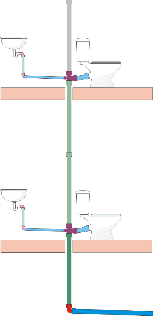
Figure 1. The simplest sewerage scheme for a two-story house.
Vertical pipelines include risers passing through all floors.
In figure 1, the riser from the second to the first floor is shown in green, the riser from the first floor to the turning point in the basement is shown in dark green, since the volume of water passing through this riser can be 2 times larger. The pipe leading from the riser to the roof is shown in grey. The fact is that wastewater does not flow through this pipe, but it is intended for sewer ventilation and to reduce pressure drops when flushing a large amount of water. And a decrease in pressure drops is necessary so that water does not wash out of the siphons of plumbing fixtures, in scientific terms, water seals do not break.
In the basement or underground, the risers are connected to the outlet
Several risers can be connected to one outlet. In Figure 1, the outlet - a horizontal pipe - is shown in blue. The outlet goes to the house sewer well, from there the pipe goes to the intra-yard sewer well and further until the sewage reaches the sewage treatment plant, but this is no longer our topic, although the principle of calculating sewer pipes up to the sewage treatment plant is the same as for intra-house sewage.
Sewerage design features
In order to correctly create an executive plan-drawing of a collector (sewage project) and calculate the number and diameter of components, it is necessary to thoroughly approach getting answers to the following questions:
- Where the riser will drain from the house from the water supply, toilet bowl and other points of water consumption. There are two options - a centralized sewerage system (here it is necessary to obtain an executive act on tie-in into the system from regulatory authorities) or drainage into a septic tank.
- What is the volume of waste per day will be processed by communication. To do this, it is necessary to calculate the number of permanent residents in the house and multiply this number by 200. It is 200 liters that is taken as an example and the rate of water consumption per person per day according to SNiP.
- It is also worth considering the features of the soil on the site, its topography and the depth of soil freezing for optimal laying of the external pipeline.
Types of sewer networks

For those who have never created a sewerage project, it is worth knowing that professionals distinguish between two types of sewerage - internal and external. Accordingly, when executing the drawing, it is necessary to prepare two collector plans.
Internal sewerage includes all plumbing points located in the building. That is, on the plan-drawing of the internal collector, it should be noted:
- An example of the location of the toilet, sink, shower and all locations of household washing equipment;
- It is also worth drawing all the pipes coming from the plumbing points, indicating their footage for each element;
- The location of the riser is also applied to the plan drawing.
The scheme should include all the turns and bends of the pipeline with the application of transition elbows.
The sewerage project for the outdoor system should also have a separate diagram on paper. This should include the following elements:
- The pipeline itself (its footage from the exit from the house to the location of the septic tank);
- In the case of a large length of the collector, it is necessary to apply the layout of revision and rotary wells to the plan drawing.
According to the type of sewerage system, the system can be non-pressure and pressure.

In the first case, the sewerage is gravity-flowing and drains spontaneously through pipes, due to the slope of the collector. Such a decision is usually made when arranging a not very long pipeline for draining wastewater into a septic tank, or provided that all plumbing points are located above the level of a horizontal riser.
Pressurized sewerage system. Here, a special fecal pump with a grinder helps to transport wastewater. Such a system is installed if, for any reason, all or several plumbing fixtures are located below the level of the riser. (Example - basement bathrooms). In addition, pressure sewage is done if the pipeline has a large length from the house to the septic tank, and at the same time, due to the characteristics of the soil, it is not possible to lay the collector under a nominal slope.
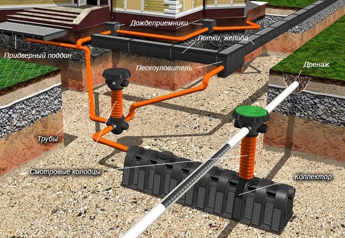
Features of the storm sewer device
The system for removing precipitation from the territory of the site may contain a different number of elements intended for certain areas of water collection. Typically, storm sewers include: storm water inlets, revision and drain wells, pipelines. The listed links of the network will be able to cope with the task, provided that they have suitable volumes.
When planning the system, it is recommended to use a special tool - a calculator for calculating the amount of storm drains. After carrying out the calculations, it is easy to select the dimensions of the elements that will be used for the device of the branch network.
Manifold hydraulics calculation formulas and tables

The executive design of the sewerage for the house should also include the hydraulic calculation of the sewer networks. This work is carried out in order to determine the optimal diameter of the pipeline, its slope and the flow rate in it. When calculating hydraulics, special formulas and tables are used. The data obtained will allow, with maximum accuracy, to select the diameter of the pipes so that the drains fill it by two-thirds at a constant speed and at the same time air circulates in the system, which will ensure the removal of gases from the pipe. In addition, the hydraulic capacity of the sewer should also be performed in order to have a margin of diameter and slope of the collector in case of increased load on it.
So, in order to correctly fill in the formula for calculating the hydraulic capacity of the reservoir, it is necessary to find out the following formula values:
- Du - outlet pipe diameter;
- V is the average speed of effluents in the pipeline;
- I is the hydraulic nominal slope of the collector;
- h/Du - filling level of the pipeline.
But these values most often do not always need to be calculated by the formula in full
Most often, the initial data is taken into account only after finding out the value of i or the value of h / Du. Since all other data can be obtained by reading the SNiP tables for the calculation and execution of the collector hydraulics
So, the value of V and the value of h / Du can be obtained from the table "Self-cleaning speed of sewage, depending on the conditional diameter of the pipeline." In addition, the minimum pipe slope according to the SNiP regulations can vary from 0.8 to 0.7 mm per meter, provided that the pipe diameter is in the range of 150-200 mm.
To derive the calculation of the hydraulic capacity of the sewer system, it is recommended to use the tables of F.A. and A.F. Shevelev and the Lukin tables. These help to calculate almost all the data for correct calculations. So, convenient for calculations are:
- Table called "Calculation of wastewater flow, liters per second";
- Table "Pipe capacity depending on the pressure of the transported liquid";
- Capacity tables for non-pressure pipes for the sewer system;
- Throughput tables for pressure sewers.
To calculate the volume of transported effluents through the collector, you must use the formula:
q=a·v.
Formula values are interpreted as follows:
- a is the cross section of the water flow in the pipe;
- v is the speed of effluent transportation, calculated in m/s.
To calculate the flow rate of wastewater, use the formula
v=C√R*i,
values are interpreted in this way:
- R is the hydraulic radius;
- C is the coefficient of wetting of the inner surface of the pipe;
- i is the slope of the collector.
To derive the value of the hydraulic slope of the pipe, use the formula
i=v2/C2*R.
It is enough to substitute here all the values \u200b\u200bobtained by the method of early calculations or taken from the relevant tables according to the estimated diameter of the pipe. The wetting coefficient of the inner surface of the collector is calculated as follows:
C=(1/n)*R1/6.
Here n is the roughness coefficient, varying from 0.012 to 0.015 depending on the pipeline material.
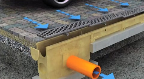
Arrangement of rain sewer rules and recommendations
The main purpose of calculating storm sewers is to determine the diameter and slope of the pipe in accordance with the amount of precipitation falling in a particular area. With insufficient pipeline capacity, the efficiency of the sewer network is significantly reduced, which increases the likelihood of flooding the area during heavy rains.
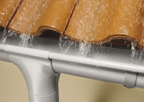
The drainage system is an important element of any construction project.
All work on the arrangement of storm sewers is regulated by SNiP. In addition to hydraulic calculations, for the correct operation of the system, it is necessary to adhere to the following recommendations:
- Domestic sewage and industrial waste must not be discharged through storm sewers.
- The place of discharge of effluents into a natural reservoir must be agreed with the sanitary and epidemiological service, as well as the bodies for the protection of water bodies.
- Surface water from the territory of private households can be sent to the central sewerage network without prior treatment. For industrial enterprises, wastewater must necessarily pass through additional treatment facilities.
- The possibility of receiving atmospheric precipitation from the territories of private and industrial facilities by urban sewerage is determined by the throughput of the central network and the performance of treatment facilities.
- The disposal of surface water, if possible, should be organized in a gravity mode.
- For large settlements and production sites, it is necessary to provide closed-type drainage systems. For low-rise suburban facilities, the use of an open sewer network is allowed.
In private houses, open and closed rainwater drainage systems are often combined.