What is the mixing unit for?
Before installing a water heating structure for the floor, you should familiarize yourself with the sanitary requirements for the relative temperature of the floor. According to the established norms, the floor temperature should not exceed more than 30 degrees, it is this optimal installation that guarantees convenience and comfort on the floor surface. Given that the pipeline is under the floor covering, the water in the pipes themselves should be about 5-10 degrees higher than in the room itself. But since the boiler of the central heating system heats water for high-temperature radiators, its temperature is 90 - 95 degrees. This is where the mixing unit is used, which, when mixing two liquids of different temperatures, optimizes the average temperature of the water for floor heating. Thanks to this, the floor remains comfortable and the concrete screed does not collapse.
So how does this device work in mixing water?
Schemes of mixing units
The scheme of the underfloor heating mixing unit is designed in such a way as to correctly obtain the coolant of the required temperature. All existing modern schemes of mixing units are divided into two large groups:
- parallel;
- consistent.
This separation takes place according to the scheme of movement of the coolant. How are both types different?
Parallel
The parallel circuit of the mixing unit for a warm floor is designed in such a way that after mixing, water of the desired temperature is supplied not only to the warm floor itself, but also to the heating circuit. This imposes features on the functioning. Since part of the prepared coolant does not enter the underfloor heating network, it is necessary to use a pump with a higher capacity.
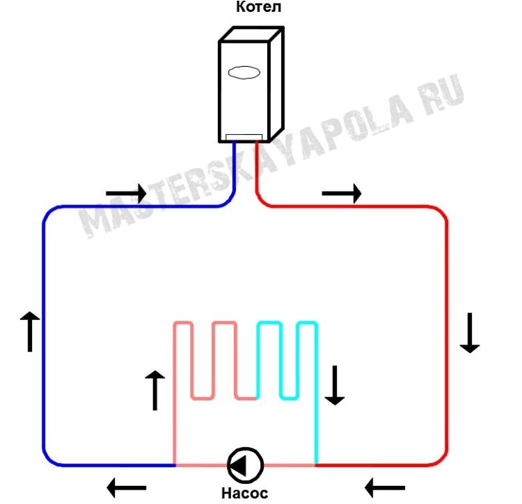
Parallel circuit.
Sequential
For the operation of a series circuit, a pump of lesser capacity is required than when using the same parallel type circuit. This is due to the fact that after mixing, the entire prepared volume of the coolant circulates directly in the underfloor heating circuit. In general, such a scheme is more suitable and is most often used in modern conditions.
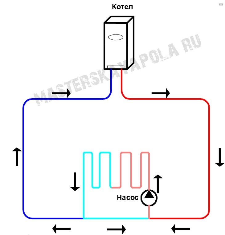
Sequential scheme.
To understand the difference between each scheme, you can read the pictures.
Mixing knot for a heat-insulated floor an element of a water heat-insulated floor. Thermostatic mixer for underfloor heating
Conducting water-heated floors in a dwelling is associated with the observance of a number of essential conditions
At the same time, it does not actually matter whether they are made in a separate room or throughout the house. Since this design does not have such a high temperature (up to 50 degrees) than the batteries we are used to (up to 90 degrees)
It is for combining these two consumers in one circuit that the mixing unit for underfloor heating is intended. In this article on the site "Our House and Yard" we will try to understand its purpose, the most important aspects of its operation and structure.
Underfloor heating faucet
The primary purpose of the underfloor heating mixing unit is to mix hot supply water with colder return water, which means that you can always control the temperature of your floor. In addition, the fulfillment of the conditions of SNiP, according to which the temperature of the liquid in the water floor system should not be higher than 55 degrees, will protect the screed from destruction, and the flooring from drying out.
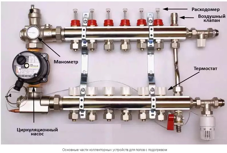
The main element of this device is a thermostatic mixer for underfloor heating, which performs the function of mixing water. Also, as a rule, the system contains a pump, without it the circulation of the coolant is not possible - the water resistance is very high due to the large length of the pipes. But for small circuits, the pump is not used.
You can buy a mixing unit for underfloor heating in specialized plumbing stores or order it on the Internet. But if you wish, or in order to save money, you can make it yourself, for this you first need to study the node diagram and purchase the elements separately.
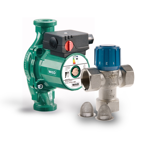
Thermostatic mixer for underfloor heating
As possible options for designs that reduce the temperature in the pipeline, you can use various thermostatic mixers:
- three-way mixer for underfloor heating with electric motor drive,
- the same valve, but with a thermal mechanical drive,
- two two-way valves as underfloor heating mixer installed on the supply line and on the bypass.
Each item following the first one can significantly reduce the cost of mixing equipment, while preventing losses in quality. At the same time, it should be understood that there are much more schemes than indicated, we have listed only the most common ones.
It is theoretically possible to completely abandon the mixer only if the boiler is not connected to heating radiators, therefore it can be set to a low temperature, or the room in which the water-heated floor is laid is small in area.
Two main types of collectors are common in the water floor system today. These are mixers with two-way and three-way valves. In any case, a thermostatic mixer for underfloor heating is implied, that is, a system that smoothly and as necessary regulates the temperature of the coolant.
Sometimes there is no thermostatic valve, then the temperature in the system is controlled manually, but in this case, increased energy costs are possible.
The most important task that the developers of thermostatic mixers sought to solve is the stability of the coolant temperature, and, in fact, the principle of operation of any thermostat is the same.
When the thermostat is open, water flows through it, and when it closes in response to an increase in the temperature of the coolant, water flows through the bypass line, preventing the heating system from further heating the floor surface.
Scheme of the mixing unit of the warm floor
Externally, the entire underfloor heating system looks like a connection of several pipelines into one. This connection can be made in a different order. In fact, there are three main types of connections: parallel, series and combined. Sequential mixing is considered the most effective; with parallel mixing, it is necessary to install two-way valves.
In accordance with the selected connection system, the scheme of the underfloor heating mixing unit also changes. The most common includes piping tees, valves on two branches - return and supply, a pump and automatic control systems.
The choice of mixing system depends on many factors, ranging from the material from which its elements are made, and ending with the features of the underfloor heating system itself.
The need for mixing units in the underfloor heating system
When installing water heating using radiators or other high-temperature equipment, the coolant can be supplied to them at almost any temperature that the boiler is capable of delivering. But the situation with underfloor heating is radically different. By building codes and common sense, there is a limit to the maximum surface temperature of the floor. Exceeding which makes the operation of the system uncomfortable and even dangerous.
For example, according to SNiP "Heating, ventilation and air conditioning", the maximum temperature of the floor, in which the built-in heating system is used, cannot exceed:
- 26 °C for permanently occupied rooms;
- 31 °C for occupancy rooms and some areas of indoor swimming pools;
- 23 °C for preschools.
These limitations make it difficult to use a boiler without a mixing unit for underfloor heating.Since without it, the coolant will inevitably raise the temperature of the warm floor above the limit value. And the temperature of the coolant can reach a level above 80 ° C.
In this case, the mixing unit of the warm floor allows the coolant of the optimum temperature to be supplied to the pipes. Is its use fundamental and is it possible to get out of the situation without it?
Mandatory use of mixing units
As we have already determined, the main purpose of the mixing unit is to maintain the temperature of the water in the system at the required level. For this, part of the water from the boiler with an elevated temperature is taken and mixed with a certain amount of water from the “return” until the required level is reached, which allows reaching the optimum floor temperature.
If the pumping and mixing unit for underfloor heating is excluded from the scheme, then it is necessary to provide temperature support in another way. As an option, a low temperature boiler can be used, which is able to provide a supply water temperature in the region of 35-38 °C in order to maintain the required floor heating. Most often, electric boilers are recommended for these purposes. Water heat pumps also operate in this mode.
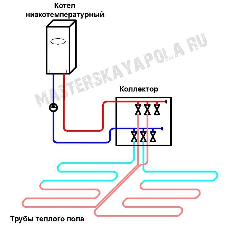
Scheme of a warm floor without a mixing unit.
It should also be borne in mind that underfloor heating without a mixing unit is practically impossible to use with a combination of floor and radiator heating, since the temperature for radiators must be high enough to ensure optimal heat transfer. If a warm floor is used as the main source, then when using a good boiler with suitable characteristics, the mixing unit may not be used.
So, if the need for a mixing unit is not in doubt, what to do in this case? It is possible to use a factory-made product that is designed and tested for trouble-free operation, but the main disadvantage of such systems is their high cost.
Alternatively, you can use a homemade mixing unit for underfloor heating. Its main advantage is a significantly lower price. On average, such a node is 3-4 times cheaper than factory-made, but questions arise in its calculation and selection of elements. After all, with the wrong selection of a warm floor, it will work unevenly or even its operation will be significantly difficult.
How to create a mixing unit with your own hands? In general, the main tasks in this formulation of the question are reduced to the following points:
- choose the scheme and design of the mixing unit;
- select the necessary elements;
- calculate pump performance and characteristics of other products;
- mount node.
Installation principles are no different from creating a heating network
The main attention should be paid to the calculation, the choice of scheme and the selection of equipment. What will we focus on next?
Features of the installation of the mixing unit
Before you independently install the design of the mixing unit, you need to read the attached instructions.
But in order to achieve the best results, you should pay attention to the following tips and recommendations from experienced professionals:
- Before installing the mixing unit, you need to choose a suitable location. This device has the properties of releasing water bubbles and condensate that appear from the outlets to the floor circuits. Also, for safety, it is necessary to exclude the ingress of water into areas that are energized. The place should be comfortable and free, in this case, installation work will not bring any special difficulties.
- The mixing unit is installed directly, near the heating system, where loops of the circuit design come out of the nutria. The unit is connected simultaneously to the pipeline pipe with hot water and the return flow line.
- After all the elements of the water system are connected to flexible pipes, the assembly itself will need to be carefully fixed to the wall.
- The device must be distributed so that the control valve is at the inlet of the pipeline heater.Before choosing pipes, you need to find out all their characteristics, since not all materials have the strength and resistance to high water temperatures in the incoming coolant. According to the recommendations of experienced professionals, the best material for this will be a polymer. Under no circumstances should galvanized pipes be chosen for this, as they are not suitable for a glycol-water solution. The pump should preferably be made of cast iron, with bronze caps and black steel tubing.
Why you need to use a mixing unit
 The most important difference between the operation of radiators, convectors and a warm floor is the temperature of the working fluid.
So for radiators, water temperature is used from 60 to 90 degrees, which directly exits the boiler. But for a warm floor, the recommended liquid temperature is about 30-40 degrees.
The principle of operation is similar to the operation of an ordinary mixer.
If we connect the circuits to the collector along with the batteries, then the warm floor will receive a large amount of heat, and this is not acceptable for a number of reasons.
- Since the screed layer above the pipes is approximately 3-6 cm, a high temperature will lead to cracking and deformation of the layer.
- Pipes that are inside the screed will experience a greater load, which will lead to local stresses, since at high temperatures the linear expansion is much greater, and the pipes are limited by a layer of concrete screed. All this will lead to a rapid failure of the pipes.
- Floor coverings do not like hot surfaces, they begin to delaminate and crack (laminate, parquet, parquet). In the case of ceramic tiles, delamination is possible. Linoleum loses its shape, dries out and deforms.
- An overheated floor surface disturbs the microclimate of the premises.
- If we accept that the floor surface will warm up to 50 degrees, then it will be impossible to walk barefoot on it.
From the above, it follows that the mixing unit is simply not replaceable. Since it is simply stupid and unprofitable to hang a separate boiler on the “warm floor” system.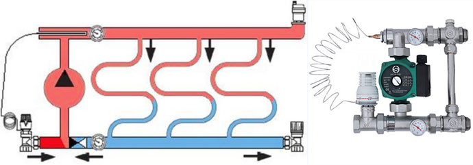
And it is not difficult to make minor changes to the heating system scheme (if the heating has already been installed). And if you mount the circuit from scratch, then this device should be provided in advance.
It should be said that there are boilers on sale that immediately provide for the technology of heating and outputting two liquid carriers of different temperatures at once. This equipment is very expensive and not popular.
This is interesting: Decorative stone effect panels for outdoor decoration
Schemes of mixing units
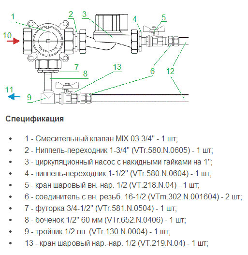
- Connectors (No. 6) are connected to the pipes.
- The supply of hot coolant from the boiler is connected to output No. 10, and the return is connected to No. 11.
- The scheme can be supplemented with an automatic air vent.
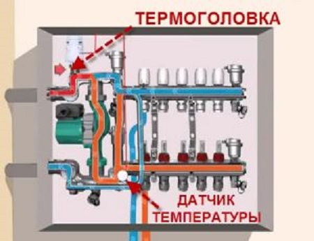
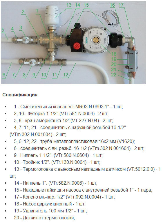 The second version of the node is also suitable for heating 15-20 sq. m., but unlike the previous version, it has automatic adjustment, due to the installed thermal head with a remote sensor.
- To connect it, the mixing valve (No. 1) is mounted with a “+” sign in the direction of the American tap from the supply.
- The supply and return are connected to American women through connectors with external threads (No. 4 - inlet, No. 7 water outlet).
- The operation of the circulation pump (No. 18) is directed towards the mixing valve (No. 1).
- The underfloor heating circuits are connected to outputs numbered 12 and 22.
 Pumping and mixing unit from Valtec
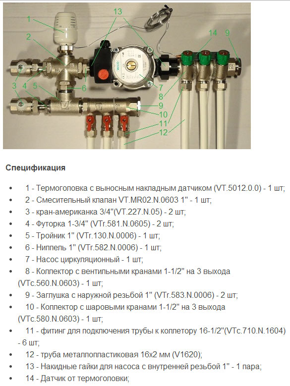
The third version of the collector unit is already suitable for 2-4 heating circuits with an area of 20-60 square meters. m. The diagram shows an example with manual control.
- To connect, the supply from the boiler is connected to terminal No. 16, and the return to terminal No. 17.
- For the system to work well, the length of the loops should be approximately the same.
- The diagram shows an option for two circuits, but if three or four pieces are to be connected, then the manifolds (9) are replaced with one adjustable manifold and one with ball valves (VTc.560n and VTc.580n).
 The following scheme is also suitable for heating rooms up to 60 square meters. m., for 2-4 circuits, but it has automatic temperature control.
- The supply is connected through the upper American tap No. 3, and the return is connected to the lower tap.
- The pump must work towards mixing valve number 2.
- The valve itself is installed with a plus sign in the direction of supply from the boiler.
- The contours for the warm floor are attached to the collectors (12).
 And the last scheme with auto-adjustment is suitable for a floor heating system for 3-12 circuits, up to 150 sq. m.
Specification:
- 1 mixing unit Combimix (VT.COMBI.0.180);
- 1 manifold assembly for the required number of outlets (VTc.594/VTc.596);
- circular pump 180 mm;
- 2 fittings (for each circuit) VT.4420.NE.16 of the Eurocone standard for connecting metal-plastic pipes.
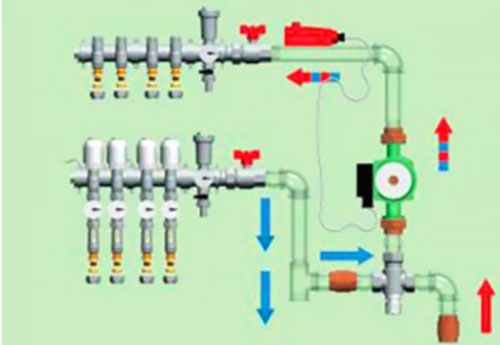
The circulation of the coolant in such a collector is shown in the figure. The supply is connected to the upper outlet, the return to the lower. The operation of the pump is directed downward, so the lower manifold becomes the supply for the underfloor heating circuits (orange in the photo), and the upper one goes to the return line (blue).
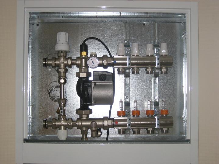 manifold cabinet
A collector for a water-heated floor is usually installed in a manifold cabinet. They are both internal and external. Their standard depth is 12 cm, so not every node can fit, especially if large thermal sensors are installed. In this case, it is better to choose an internal cabinet, the depth of which is increased by deepening the back wall.
Thermostatic three-way mixer AQUAMIX 63C for underfloor heating
Where is it applied?
-
When the cottage has a combined heating system: radiators + underfloor heating;
-
When the power of underfloor heating does not exceed 11 kW;
-
When you need to save on a ready-made pumping and mixing module;
What is special about this valve?
-
Maintains the temperature of the mixed water with an accuracy of 1 to 2°C, in the range from 25 to 50°C;
-
Permanent bypass between return and mixed water;
-
The inner surface is coated with Teflon to reduce scale in hard water;
-
Built-in protection against overheating in emergency situations;
-
Two mesh filters for protection against mechanical pollution;
-
Installation in any position;
| Operating mode in the process of mixing hot water | Circulation mode through TP without admixture |
 |
 |
Mixed water temperature setting
The mixing temperature setting table is given for a temperature of 60 degrees at the "plus" inlet, and a temperature of 25 degrees at the "minus" inlet. Monitor the temperature of the mixed water with a thermometer.

What area of underfloor heating can serve?
 |
It depends on the power of the circulation pump in the "warm floor" system and on what kind of heat transfer you want to get from 1 m2 of floor Below is a table showing the power of various options for the combined use of thermal mixers and circulation pumps. The calculation was made with a standard connection of underfloor heating to the pumping module (through a manifold for WATTS underfloor heating) and the resistance of each branch of the underfloor heating |
|
Underfloor heating damper AQUAMIX 63C (range 25-50°С) |
vendor code |
Consumption, l/min |
Heat transfer, kW at Тpod-Тоbr=10°С |
| Three-way thermal mixer AQUAMIX 6310C34 3/4″BP 25-50°С (kvs1.9) with pump* Wilo 25/4 (pipes for piping valve and pump ¾" or 1") | 10017420 |
10 |
7,0 |
| Three-way thermostatic mixer AQUAMIX 6310C34 3/4″BP 25-50°C (kvs1.9) with pump* Wilo 25/6 (pipes for piping valve and pump ¾” or 1″) | 10017420 |
16 |
11,2 |
| Three-way thermal mixer AQUAMIX 6311C1 1″BP 25-50°С (kvs2.1) with pump* Wilo 25/4 (pipes for piping valve and pump ¾" or 1") | 10017421 |
10 |
7,0 |
| Three-way thermostatic mixer AQUAMIX 6311C1 1″ВР 25-50°С (kvs2.1) with pump* Wilo 25/6 (pipes for piping valve and pump ¾” or 1″) | 10017421 |
16 |
11,2 |
* - the circulation pump and branch pipes are not included in the delivery set of the valve;
Example:
Let's say we use a pipe for underfloor heating 16x2. At the same time, we need to provide heat transfer of 88 W / m2, floor temperature of 28 ° C, air temperature in the room of 20 ° C. According to our calculation method, in order to achieve these conditions, we lay the pipe with a pitch of 200 mm, and set the supply temperature to the warm floor at 45°C. We have 5 rooms of 15m2.If for each branch of the warm floor we provide a flow of 2 l / min., Then the total flow will be 10 l / min.
To solve this problem, we select the valve 6310C34 3/4″BP 25-50°С (kvs1.9, article 10017420) and the pump WILO 25/4. For strapping, we use pipes with a diameter of 1”. Since we know that the temperature in the radiator circuit is 60°C, we set the handwheel on the Aquamix mixing valve to position 8, corresponding to a mixed water value of 44.4°C.
How to install?
Scheme for a combined heating system underfloor heating + radiators
Specification
|
Position |
vendor code |
Name |
|
Three-way thermal mixer AQUAMIX 6310C34 3/4″BP 25-50°С (kvs1.9) |
||
|
AS-20 set of two ball valves with 3/4″ M x 1″ M threaded connection |
||
|
Underfloor heating circulation pump 25/4 |
||
|
Room thermostat WFHT-Basic + for air temperature control |
||
|
External temperature sensor (floor sensor) SENSOR10K |
||
|
Electrothermal actuator manifold 22CX |
||
|
Underfloor heating collector with HKV-T flowmeters for 5 outlets |
||
|
Straight fitting for connecting a radiator DG 3/4″х3/4″ |
||
|
Surface-mounted emergency thermostat WTC set to 60°C |
||
|
Thermal head 148A (thread 30×1.5) |
|
Position |
vendor code |
Name |
|
Three-way thermal mixer AQUAMIX 6311C1 1″BP 25-50°С (kvs2.1) |
||
|
AS-20 set of two ball valves with 3/4″ M x 1″ M threaded connection |
||
|
Underfloor heating circulation pump |
||
|
Room thermostat WFHT-Basic + for air temperature control |
||
|
External temperature sensor (floor sensor) SENSOR10K |
||
|
Basic control module WFHC for underfloor heating with 6 thermostats, turns off the pump when all actuators on the collector are closed |
||
|
Electrothermal actuator manifold 22CX |
||
|
Underfloor heating collector with HKV-T flowmeters for 5 outlets |
||
|
Surface-mounted emergency thermostat WTC set to 60°C |