Design rules for control systems
Systems Design SODK
is carried out on the basis of the provisions of GOST 30732-2006 and the Code of Rules 41-105-2002. The design organization develops and transfers to the customer a set of documents, including the rationale for the structure and composition SODK
, a master plan indicating the places where cable outlets are provided, installation of carpets and switching terminals, diagrams of electrical connections and wiring in the terminals. A separate document contains a list of measuring equipment, control devices and devices for finding faults, recommendations for installation work and subsequent maintenance of the system SODK
.
At the design stage, it is important to determine the most optimal distances between the cable outlets and to indicate exactly where the carpets are to be installed. It is recommended to have intermediate control points and corresponding SODK terminals
at a distance of no more than 300 meters from each other
At each end of the route, it is necessary to provide for the installation of end cable outlets and terminals designed to connect stationary and portable detectors. All equipment should be located in such a way as to simplify the operation of the SODK
and ensure maximum accuracy in the production of control and diagnostic measurements.
Types of malfunctions and search for places of damage
During operation, the system SODK
monitors one of the most important parameters of the state of the pipeline - the absence or presence of moisture in the thermal insulation layer, and its own state - the serviceability of the signal wire. Accordingly, based on the measurement results, the system can fix any of the following faults:
- Wetting of a separate section of thermal insulation.
- Short circuit when the signal conductor contacts the surface of the working tube.
- Damage (break) of the signal conductor.
The search and localization of the defect site is carried out using portable and stationary detectors, and the most accurate and efficient device - a pulsed reflectometer. Detectors help to determine the area between control points where a malfunction is detected. This section of the circuit is temporarily turned off, and by sending a control high-frequency pulse through the wires, data is obtained on the time of passage of the reflected signal. By comparing the data obtained from each side of the control section, the distance to the accident site is calculated.
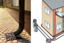
SODK system for pipeline control
The UEC system allows you to monitor the condition of the pipeline, promptly signal a malfunction and accurately indicate the location of any defect. The presence of the UEC system significantly saves money and reduces the time spent on pipeline maintenance.
The control system allows to detect the following defects:
- Damage to a metal pipe (fistula).
- Damage to the polyethylene sheath.
- Breakage of signal conductors.
- Shorting the signal conductors to a metal pipe.
- Poor connection of signal wires at the joints.
Composition of the UEC system
The operational-remote control system is a special set of instruments and auxiliary equipment (which will be referred to as elements of the UEC system in the future) with the help of which the condition of the pipeline is monitored. The exclusion of any element from the system violates its integrity and normative functionality.
The control system includes the following components:
- Signal conductors
- Control and measuring equipment (damage detectors, pulse reflectometer - locator, control and installation device "Robin KMP 3050 DL").
- Switching terminals.
- Connecting cables.
- Ground and wall carpets.
- Materials and equipment for installation.
Purpose, principle of operation and technical implementation of SODK
Ability to create an electronic system SODK
, which controls the state of the thermal insulation layer of PPU pipes and the tightness of their outer shell, favorably distinguishes this type of pre-insulated pipes and greatly increases the reliability of industrial pipelines built from them. Designed to continuously monitor the moisture content of the entire volume of PU foam insulation, the system SODK
allows you to guaranteedly avoid accidents associated with the penetration of water to the surface of working steel pipes, and - as a result, damage to them by corrosion.
In addition, in the event of a violation of the tightness of the outer shell and wetting of polyurethane foam, its thermal conductivity sharply increases, which significantly worsens the thermal insulation properties of this section of the pipeline. Timely detection of defects in pipe insulation using the hardware complex of the system SODK
allows you to quickly make the necessary repairs to the damaged area, to prevent uncontrolled development of the situation and the significant material damage associated with it.
UEC system purpose, principle of operation, correction of damage
What is ODK? This is a system of operational remote control. Produces constant and continuous monitoring (PPU). Monitoring is carried out throughout the service life of the heating main.
The system is designed to detect such defects as:
- damage to the pipe itself;
- damage to the polyethylene wrapper that wraps the pipe and the thermal insulation layer;
- damage to signal wires;
- the process of closing the signal wires to the pipe;
- poor butt connection of wires.
The principle of operation of the UEC is based on a sensor that controls the insulation layer, namely its humidity, which runs along the entire length of the pipeline. At least two wires are located in the thermal insulation layer and connected along the entire length of the pipeline. At the start and end points, they are connected into one loop. The loop is copper signal wires. Between the steel pipes and the polyurethane foam layer of thermal insulation, a sensor is formed to control the moisture level of the thermal insulation.
Sensor tasks:
- control of the entire length of the sensor and control of the length of the signal loop. Identification of the length of the section of the pipeline that is covered by the sensor;
- moisture control of the thermal insulation layer;
- search for the place where the thermal insulation layer has been moistened or the signal wire has broken.
The task of the sensor is to provide accurate data on the moisture content of the thermal insulation. When the amount of moisture increases in the thermal insulation layer, it means that it can be either a coolant leak from the pipe or moisture from the outside. As soon as this happens, the sensor reports by reflecting the pulse.
The principle of recognition of the damage site and its elimination:
- as soon as the thermal insulation is broken, the sensor reports this. It remains to find damage in the area that is between the signal indicators;
- the allocated site is disconnected from the UEC system;
- overlaying data on the joint scheme;
- based on the data obtained, the required section of the pipeline is dug out and repairs are carried out.
Operating principle
Operation of hardware control complexes SODK
is based on the principle of measuring the resistance of the thermal insulation layer to electric current. Being a dielectric under normal conditions, wet polyurethane foam becomes a conductor - its resistance drops to 1.0-5.0 kOhm, which can be recorded by appropriate devices SODK
. To ensure the possibility of making such measurements simultaneously along the entire length of the pipeline, PPU pipes are equipped with special conductors integrated into the polyurethane foam layer at the stage of manufacturing thermal insulation.
Later, during the construction of pipelines, the conductors of all installed pipes are connected into a single circuit. By measuring the electrical resistance of the transition "steel pipe - signal wire SODK
, the system equipment is able to register any, even the most insignificant, deviation of the actual parameters from the reference values entered in the technical passport of the pipeline at the time of the start-up tests. If SODK
registered the presence of insulation wetting, with the help of special remote-action devices - pulse reflectometers, the location of the defect is determined with a high degree of accuracy and repairs are promptly carried out.
What does the UEC system consist of?
Built-in copper wire. It is the conductor through which the damage signal is transmitted. It is located in a heat-insulating layer of polyurethane foam. Without it, the UEC system will not work.
There are two types of wire:
- basic. It repeats the contour of the pipeline and is stretched along the entire path of the heating main;
- transit. Designed to form a signal loop and runs along the shortest path between the start and end points of the heat pipe.
Devices for control and measurements:
- damage detectors. They monitor the breakage or short circuit of the built-in signal wire. They do not establish the cause of the damage, but state the fact. The stationary detector (220 V) provides constant control, the portable one (9 V) provides periodic control. The first option can control from one to four pipelines. Has an alarm system. The second option works autonomously, powered by a battery. Able to serve an unlimited number of pipelines. They are installed at control points using a switching terminal;
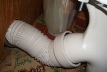
- pulse reflectometer. Able not only to fix the damage, but also to find its location. Does not provide information about the causes of the defect. Connected at the factory and before installation to the ends of the pipes in those places where the signal wires come out of the insulation. It is also connected during control, directly during the operation of the heating main.
The switching terminal of the UEC system is presented as an intermediate link between the control devices and the pipe. Usually they are placed from each other at a distance of 300 meters. They are used to connect control devices, as well as switching signal wires.
UEC system
The Operational Remote Control System is a set of detectors for various cables, conductors, terminals and other elements of the system. Most of the elements are installed during installation. In the production of pipes in polyurethane foam insulation, at the stage of formation of the finished product, to ensure the operability of the UEC system, conductors are mounted in the insulation layer.
In accordance with clause 5.1.9 of GOST 30732-2006, copper wire with a cross section of 1.5 mm2, made from low-alloy copper of the MM grade, is used as conductors. The conductors are located parallel to the axis of the pipe in the plane of one section at a distance of (20 ± 2) mm from the steel pipe. The conductors are fixed in centering supports, which in turn are attached to the steel pipe.
The distance between the centering supports should be from 0.8 to 1.2 m. In the case of the upper location of the longitudinal seam of the steel pipe, the conductors should be in the 3 and 9 o'clock position. In case the pipe diameter is 530 mm or more, three indicator conductors must be installed at the 3, 9 and 12 o'clock positions.
In accordance with clause 4.59 of SP 41-105-2002, on the right, in the direction of water supply to the consumer, the main signal wire is installed.The second signal wire is transit. The difference between the signal conductor and the transit conductor is that the signal conductor enters all branches of the heating main, repeating its entire contour, and the transit conductor - along the shortest path between the start and end points.
In accordance with paragraph 5.1.10 of GOST 30732-2006, the resistance between the steel pipe and the conductors of the UEC system must be at least 100 MΩ at a test voltage of at least 500 V.
In accordance with clause 3.9 of SP 41-105-2002, the resistance of copper conductors-indicators should be in the range of 0.012-0.015 Ohm / m. Insulation resistance 3.3 kOhm/m.
In accordance with clause 4.57 of SP 41-105-2002, the threshold resistance of copper conductors-indicators should be 200 ohms with a maximum length of 5000 m. If this parameter is exceeded, the detector generates a “Break” signal. The threshold insulation resistance should correspond to 1-5 kOhm. If the insulation resistance parameter is lower, then the detector generates a "wet" signal.
Our production
Pipes in PU insulation
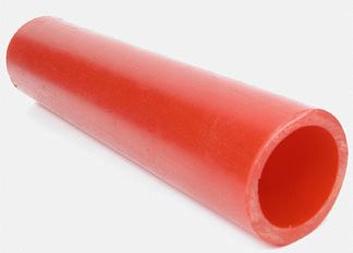
shell ppu
thermal tape
Sealing kit (KZS)
Fixed shield supports (NSCHO) in polyurethane foam insulation
Thermal cameras
Channels impassable (trays of heating mains)
Signal conductors
Purpose
All pipelines and fittings (tees, bends, valves, fixed supports, compensators) must be equipped with signal conductors. With the help of signal wires (a signal is transmitted through them - a current or a high-frequency pulse), the state of the pipeline is determined.
Conductor configuration
The signal wires installed inside the thermal insulation layer of polyurethane foam are pulled parallel to the manufactured pipe and geometrically placed at “3” and “9” or “2” and “10” hours.
Functional purpose of conductors
The wires to be mounted are exactly the same, however, according to their purpose, they are divided into the main and transit wires. The main wire is a signal conductor that enters all its branches during the installation of the heating main. This wire is the main one for determining the state of the pipeline, as it repeats its contour. The transit wire is a signal conductor that does not go into any branch of the heating main, but runs along the shortest path between the start and end points of the pipeline and mainly serves to form a signal loop .
Installation of conductors during construction
During the construction of the heating main, the installation of conductors is carried out at the butt joints of the pipeline. The installation of wires must be carried out in such a way that the main signal wire is on the right in the direction of water supply to the consumer on all pipelines, and all side branches must be included in the break of the main signal conductor. It is forbidden to connect side branches to the transit wire.
Connecting wires at the joints
The signal wires are connected to each other, respectively: the main with the main, and the transit with the transit. With the help of pliers, the wires twisted into a spiral are carefully straightened and stretched and, avoiding kinks, are arranged parallel inside. The wires are cleaned with sandpaper from the remnants of foam and paint, and then they are thoroughly degreased. The wires should be pulled and cut off excess parts so that there is no slack during the connection. Insert the ends of the wires into the crimp sleeve and crimp the sleeve on both sides using crimping pliers. After that, the resulting connection must be irradiated with an inactive flux, solder POS-61 and a gas soldering iron (or electric, if there is a 220V power supply), the wire connection is heated with a soldering iron, after a few seconds it heats up to the melting temperature of the solder. The connection is soldered correctly when the solder fills the crimp sleeve on both sides. To check the correctness connections need to be pulled by the signal wires to check if the splice is in order.
Today, different materials are used for heating. One of them is polyurethane foam. His popularity is on the rise. But like any material, it can be damaged. The UEC system for PPU pipes comes to the rescue.It controls the insulating layer of the pipeline. Thanks to the JEC, it is possible to prevent damage to the pipe by taking timely measures. This reduces repair time and costs.
PPU pipes are a new and promising development
The question remains, what is PPU? Everything is pretty simple. These are polyurethane foams - a universal group of polymers. The material is new, but already gained its popularity.
The Russian climate forces us to heat our homes. And the acute question is not how to bring heat into the house, but how to bring it with the least loss. Previously, the pipeline was wrapped with glass wool, fixed with steel wire, and covered with galvanized steel sheets on top. The material is valuable, so it did not stay long on the pipes. Today, more and more pipes are made of polyurethane foam. It is also used for thermal insulation.
Advantages of PPU:
Stages of installation of PPU pipes:
- sweep;
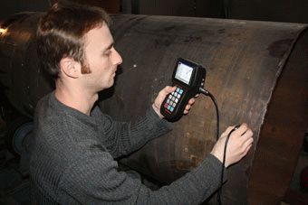
- welding and quality control;
- for this purpose, a flaw detector is needed;
- putting on the clutch. Mounting foam is poured under it. The sleeve heats up and shrinks. This allows you to get the tightness of the connection.
The UEC system for a heating main is an additional method of protection. And it consists in preventing large emergencies and eliminating small damage as quickly as possible.
The composition of the UEC equipment
The whole complex of technical means SODK
It is customary to conditionally divide into three groups - the pipe part, signaling equipment and a group of additional devices. The pipe part includes all passive electrical elements - from conductors embedded in pipes and connecting mounting accessories, to intermediate and end cable outlets. To signal group SODK
include the active part of the equipment - measuring instruments, matching devices and switching facilities.
A group of additional devices is formed by securely closing ground and wall metal structures - carpets, in which, during the installation of the system, the equipment of the signal group is installed. Thus, the composition of the equipment SODK
includes:
1.Pipe part
- conductors mounted in pipes, all mounting and connecting accessories and cable outlets.2.Signal group
- active equipment SODK
: 2-1. Control devices: stationary and portable damage detectors. 2-2.Instrumental means of localizing the defect - pulsed reflectometers. 2-3. Equipment installed in control rooms. 2-4. Auxiliary devices - insulation testers, ohmmeters and megohmmeters. 2-5. Switching measuring terminals. There are end, double end and intermediate terminal boxes. 2-6. Sealed terminals - securely closed wiring boxes that protect connections and connected devices from moisture. Distinguish end, uniting and through tight terminals. 3. Additional devices
- ground and wall metal carpets.
One of the most costly components of equipment SODK
are control devices and technical means of troubleshooting. Monitoring devices include stationary and portable detectors, each of which is capable of monitoring sections of pipelines from 2000 to 5000 meters long. Domestic manufacturers produce a line of high-quality devices that allow you to completely abandon the purchase of imported equipment - Vector-2000, SD-M2 (NPP Vector), PIKCON DPS-2A / 2AM / 4A, DPP-A / AM (LLC "Termoline"). The group of damage search instruments also includes Russian-made equipment REIS-105/205 (Stell Research and Production Enterprise) and RI-10M/20M (Oersted CJSC).