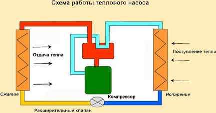
How a heat pump works
The heat pump is based on the unique Carnot cycle, with its own circular process. According to this scheme, the heat pump is able to pump in a circle the dissipated heat taken from the ground, water or air.
This approach makes it possible to collect almost 75% of the heat energy by the heat pump, but 25% of the energy is required for the operation of the equipment itself. For this reason, a heat pump cannot do without the consumption of electricity, which is necessary for its efficient operation. At the same time, consuming only 1 kW of electricity, the heat pump is able to give 5-7 times more.
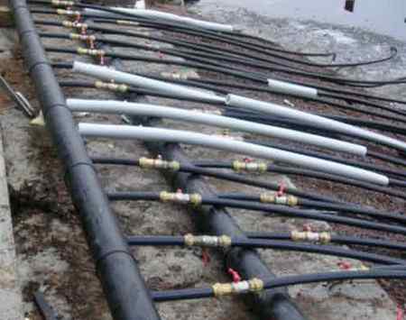
The principle of operation of a heat pump is very similar to a conventional refrigerator or air conditioner, which we are used to using on a daily basis. For example, deep underground (below freezing of the ground level) or at the bottom of a reservoir, pipes are laid according to the scheme of warm floors, through which the coolant circulates all the time.
The temperature underground, at the depth of which the pipes are laid, is always constant, with a plus mark. Therefore, the coolant does not heat up too much, only a few degrees. Then, getting into the evaporator of the heat pump, it gives off the collected heat to the internal circuit, and here the fun begins.
In the internal circuit of the heat pump there is freon (refrigerant), which enters the evaporator under high pressure, and takes away part of the heat given off by the coolant to the walls of the evaporator. Then the refrigerant enters the heat pump compressor, where it is compressed, heated and pushed into the condenser.
Already in the heat pump condenser, the heat is taken directly to the heating system or hot water supply of the house (through a heat exchanger). The cycle of heat transfer then repeats over and over again, which is how a heat pump works.
Types of heat pumps
Today, there are various types of heat pumps, for example, a ground-to-water heat pump, or an air-to-air heat pump. Consider briefly the existing types of heat pumps:
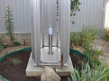
Ground-to-water heat pump: These are geothermal heat pumps that are designed to take heat from the ground and transfer it to the house, transferring it through the coolant that circulates in the heating system.
Water-to-water heat pump: Heat, when using a water-to-water heat pump, is extracted in this case from a well or a well. To do this, a special hydraulic unit installed in the heat pump pumps ground water, takes heat and dumps it back into the well-borehole. This type of heat pump is remarkable in that it is possible to use an existing well on the site in order to make geothermal heating in your home.
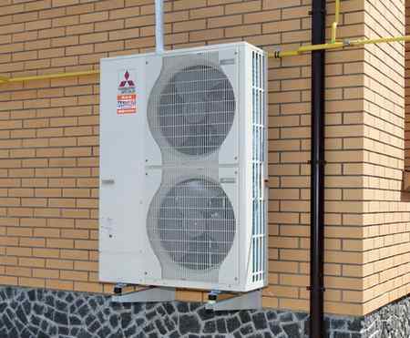
Air-to-water heat pump: The source of heat in this type of heat pump is the ambient air. Consuming only 1 kW of electricity, an air source heat pump can increase it to 5 kW for heating and hot water.
Air-to-air heat pump: The air-to-air heat pump works in the same way as a home air conditioner that heats rooms. The difference lies only in the efficiency of operation, since air-to-air heat pumps are almost 3 times more efficient than any air conditioners with a heating function.
Of course, heat pumps, as well as other sources of alternative energy, are the future. When the oil and gas reserves on Earth will be depleted, a reboot will be needed, and then the energy of the sun, earth and wind will come to the rescue, allowing all of humanity to survive.
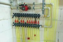
The principle of operation of the circulation pump
To understand how the circulation pump works, you do not need to be a great specialist. Its task is to overcome the friction inside the heating system and organize the non-stop movement of the coolant. The motor pushes the liquid through the pipes with the help of a rotor. If the circulation pump does not work, the coolant will move through the system by inertia for some time, and then it will stop completely. On an industrial scale, pumps are produced with two types of rotor, the so-called dry or wet. The first type of rotor is used for heating industrial premises with a large area, where the noise level of a running pump is not of fundamental importance. The high performance level of the instrument compensates for the need for constant lubrication of the moving parts of the pump. A pump with a wet type of rotor is used for heating residential premises. The coolant in which the rotor is immersed simultaneously lubricates and cools the engine. The absence of a fan and the presence of a protective casing make the operation of the unit so quiet that it is almost inaudible how the circulation pump works.
The principle of operation of the wet rotor circulation pump is such that the unit can operate in a room with low air pollution and pump purified water or a water-clicol mixture. Oil is not used as a heat carrier in a heating system with a circulation pump.
Despite the seemingly simple principle of operation of the circulation pump, it is possible to select the desired device only with the help of a specially trained employee who can correctly calculate the parameters of the required unit and connect it to the heating system. A pump with excessive power will create unpleasant noises in the heating system, caused by an increased speed of the coolant and uses more energy.
The question of the need for a pump power reserve remains controversial among specialists even now. Some believe that the pump operates at full capacity only a few days a year, and the rest of the time it consumes additional energy, which is absolutely not rational. Others argue that working at the limit of its capabilities, the unit will quickly wear out and fail.
To correct the operation of the pump, devices with power control are produced. The pump can be adjusted manually or automatically. Manual adjustment has three modes of rotor speed, each of which affects the speed of the coolant. In warmer weather, you can save energy by setting the pump to the lowest setting.
More expensive modern pumps with automatic power control can be successfully used in a floor heating system or a heating system with heating temperature controllers on radiators. Automation is able to catch the slightest changes in the system and correct the corresponding settings of the pump.
How to install a circulation pump for heating
For owners of country houses with a local heating system, the issue of uniform distribution of heat between all rooms is especially acute. For this, systems of natural circulation of the coolant are used.
Circulation pump gets hot
In heating systems, circulation pumps are used for uniform circulation of the coolant. The pumps transfer the working fluid from the boiler to the heaters, and when the fluid cools down, back to the boiler. Everything.
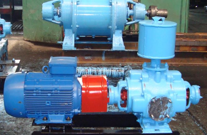
Centrifugal
The most common type of feed device in boiler plants is the centrifugal pump. Centrifugal feed pumps are manufactured as single or multi-stage, depending on the flow and operating pressure, and are driven by an electric motor or a steam turbine.
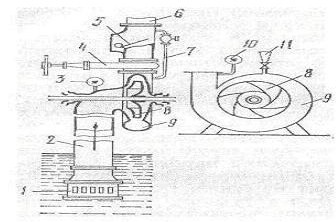
The pump consists of impellers rotating on a shaft and a volute casing. Before starting, the pump is filled with water.During pump operation, water enters it through a suction pipeline with a suction valve and a mesh that protects the valve from clogging. Getting on the blades of the impeller in the axial direction, the water is picked up by the blades and, under the action of centrifugal force, is thrown into the volute-shaped channel surrounding the rotating wheel, and then into the discharge pipeline.
When water is ejected from the impeller, a vacuum is created in its central part, due to which, under external pressure, water enters the pump through the suction pipeline. Thus, with the continuous rotation of the impeller, the water moves continuously through the pump.
As the water exits the pump, the velocity of the water increases and the pressure decreases. In order for water to enter the boiler, the discharge pressure must be greater than the steam pressure in the boiler. To reduce the speed of movement and increase the discharge pressure, a guide vane (and here about heat exchangers) is mounted on most pumps, which is a disk with blades bent in the direction opposite to the direction of the impeller blades bend. The outlet sections of the guide disc blades expand.
To increase the pump flow, the impeller is made with double-sided suction, that is, water is supplied to it from two sides. The pressure created by one impeller usually does not exceed 50 m. To create high pressures, centrifugal pumps are made with several impellers arranged in series one after the other on one common shaft. Water sequentially passes from one wheel to another. The pressure generated by a multistage pump is equal to the sum of the pressures generated by each impeller.
On the centrifugal pump, pressure gauges and valves are installed on the suction and discharge pipelines, a check valve on the discharge pipeline, air release valves in the upper part of the housing of each stage.
Compared to piston centrifugal pumps, they have a large flow, smaller overall dimensions, and create a more uniform water supply (without shocks).
The disadvantages of centrifugal pumps are the mandatory filling of the pump with water before start-up, the high cost of operation at high pressures, the dependence of the suction height on the water temperature.
How VVN works
The liquid ring vacuum pump is the most popular type of equipment used for pumping gaseous media from closed spaces. For the operation of such devices, a liquid working medium is needed, which is mainly used as water (less often - oil, antifreeze, alkalis, acids and other substances). The design scheme of pumps of this type includes a wheel with blades, which is the main working body of such devices.
The principle by which VVN works is quite simple. It consists in the following.
- Under the influence of the rotation of the paddle wheel, which creates centrifugal force, the liquid is thrown to the walls of the working chamber, forming a water ring along its inner perimeter.
- In the central part of the working chamber, as a result of the above process, a rarefaction zone is created, which ensures the suction of the evacuated gas medium into such a chamber through the inlet pipe.
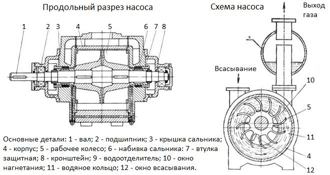
The principle of operation and the main details of the VVN pump
It should be borne in mind: the principle of operation of vacuum pumps of this type implies that the liquid working medium is constantly heated, so it must be changed regularly.
The device and principle of operation of liquid ring vacuum pumps are quite simple, which ensures high reliability of such equipment, as well as ease of operation, maintenance and repair.
Liquid ring vacuum pumps do not require purification of pumped gases and ways to work around the clock
How does a circulation pump work
The private houses in which our parents live were built with their own hands, which is noticeable by the illiterate layouts of the premises, not always even windows and doors, and littered walls. Everyone installed heating as they understood, the principle was the same: the slope must be maintained so that water can constantly circulate through the system.
The operation of the circulation pump takes us to a new era of heating systems. Its presence in the system makes it much more economical. The pipe diameter can be significantly smaller, which significantly reduces the volume of the coolant. The liquid moves through the heating system at a certain speed, which allows you to evenly heat the premises, maintain the most comfortable temperature in them, and it heats up, if necessary, quite quickly. The automatic mode of operation of the circulation pump allows the device to instantly respond to various changes in the system, changing the settings of the device and making the operation of the heating equipment more economical. Heating a house with several floors is unthinkable without such a pump, and the continuous circulation of the coolant, in addition to all these advantages, also protects the heating boiler from erosion.
Pump repair and maintenance
Before purchasing a repair kit for pump revision, pay attention to the design of the seal and the size of the shaft rotation bearings, since the dimensions of the parts differ depending on the year of manufacture of the pump. Types of water pump repair kits MTZ 80
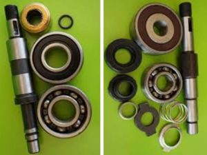 Types of water pump repair kits MTZ 80
Assembly disassembly
The inconvenience of the dismantling process of the pump lies in the narrow distance between the block and the radiator of the MTZ 80 tractor. The success of a quick disconnect depends on the availability of an arsenal of socket wrenches and knobs for them corresponding to the design features of the assembly, as well as the professionalism of the locksmith.
To disconnect the node from the block, operations are performed in the following sequence:
- Raise the tractor hood
- Loosen the fastening of the tension and mounting bracket of the generator
- Remove drive belt
- Unscrew the radiator diffuser
- Disconnect hoses from pump
- Loosen the three bolts securing the pump to the block and remove the assembly.
Pump disassembly
The presence of locksmith's bars for fixing and a screw puller for pressing the pulley hub and shaft with bearings will ensure quick and comfortable disassembly of the unit.
The pump is disassembled in the following order:
- Release the fixing bolt and remove the impeller with seals from the shaft
- The mounting bolts on the drive pulley hub are unscrewed, disconnecting the fan
- The central nut fixing the pulley on the shaft is unscrewed
- Having fixed the pump housing in a tight grip, using a screw puller or gentle blows on the circumference of the inner pulley crown, remove the part from the shaft keyway
- Dismantle the retaining ring that fixes the shaft with bearings in the housing bore
- The shaft with bearings is pressed out using a screw puller or by careful blows to the end of the shaft from the side of the impeller, having previously screwed the fixing bolt into the shaft so as not to splash the end of the part with an internal thread.
 Pressing out the pump shaft
After disassembly, clean the body and impeller from dirt and scale
Particular attention is paid to the contact surfaces of seals and gaskets. With the help of sandpaper, scale deposits and small shells are cleaned on the contact planes with seals, especially in the pump housing around the shaft hole
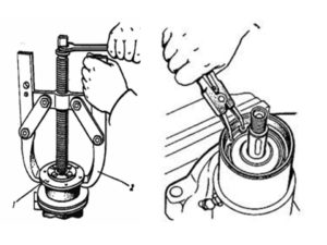 Removing the pulley and circlip
In case of detection of large potholes or shells that cannot be cleaned, the assembly body must be replaced. A shaft with an unacceptable wear in the landing spaces, bearings with axial play in the cages are also changed. To achieve a positive result when eliminating a pump leak, the secondary use of seals and seals is unacceptable.
Assembly and installation
The assembly process is carried out in reverse order. All parts of the pump must take their seats. The result of proper assembly is the free rotation of the impeller by hand without distortions and hooks on the housing, without axial play in the shaft and impeller seats. The crucial moment in the assembly of the assembly is the landing of the pulley hub on the shaft key
When pressing the part onto the shaft, it is important not to displace the key from the mounting groove and to ensure a reliable connection without radial and axial play. Connection is carried out with carefully cleaned contact surfaces of the block and the pump through a new gasket
For a comfortable future revision of the assembly, instead of the standard impeller mounting bolt, experienced tractor operators install a similar brass part, thus preventing the formation of corrosion, which makes disassembly difficult.
Service
Pump maintenance operations include checking the tension of the drive belt and timely lubrication of the bearings of the assembly. Scheduled lubrication is carried out by injection through the grease fitting during maintenance 1. The belt tension is changed by the position of the generator when the mounting bracket is turned.
The correct tension ensures the belt runs with minimal slippage and is controlled by the deflection of the middle of the large branch of the drive “alternator pulley - crankshaft pulley” when pressed with a force of 30 ... 50 N by 10 ... 15 mm. Control is carried out every 60 hours of operation. When commissioning a new engine, the tension is checked no later than after 2 to 3 work shifts. Excessive tension increases the load on the support bearings of the drive units and accelerates their wear.
Pump malfunctions
The reason for the wear of parts and the subsequent failure of the assembly is a violation of the tightness of the seals. The destruction of the seals occurs as a result of the action of temperature, mechanical loads during rotation, as well as friction when solid particles of oxide and scale enter the engine water jacket.
If a slight leak of the pump is detected, it is recommended to carry out an audit with the replacement of the seals of the assembly. Ignoring leads to unacceptable wear of parts, which subsequently increases the repair budget. An unfortunate result of untimely maintenance is the discovery, during disassembly of the pump, of mechanical chips and potholes of the cast-iron casing in the places where the seal fits. Often, replacing seals in a damaged housing does not give a positive effect and the pump continues to leak. In the end, you have to purchase and install a new node.
 Assembly scheme MTZ 80
Some "kulibins", in order to extend the operational life of the pump, drill a hole for the shaft in the volute to a larger diameter. A stainless bushing with outer rubber rings is installed in the bored hole, and self-locking oil seals are selected in the end groove of the bushing from the impeller side. The success of such a restoration depends on the accuracy of the fit of the sleeve and the tightness of the seals.
Also, an additional risk in the event of unacceptable axial clearances in the rotation bearings of the pump shaft may be damage to the radiator by the fan blades. Runout during bearing wear can cause destruction of the key connection and the seat of the pulley with the shaft. Given the constant axial load from the drive belt tension force, when developing unacceptable gaps, the pulley with the fan moves towards the radiator, thus damaging the heat exchanger with blades.
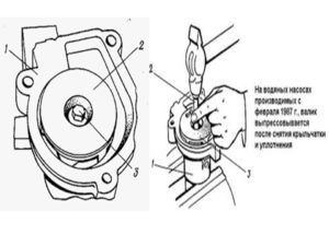
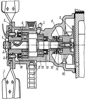
Pump device
The unit is assembled in a cast iron housing 14, consisting of two compartments: the water part in the form of a snail, where the impeller 9 of the pump is installed; oil - with two shaft support bearings 4. The snail is fastened with a milled connecting surface through a gasket to the block with three bolts, combining the working discharge cavity of the pump with the longitudinal line of the water jacket of the cylinder block.
The impeller is seated on the grooves of the shaft and fixed with an end bolt through a washer and a sealing rubber ring. The water cavity of the snail with the impeller is separated from the oil cavity of the assembly by a partition and a seal, the tightness of which is ensured by a textolite washer 12 adjacent to the carefully ground end of the thrust sleeve pressed into the body, as well as by a spring 8 of the rubber cuff 11, enclosed in a cage.
 Scheme of the device pump MTZ 80 (82)
The vacuum created by the rotation of the impeller sucks in coolant from the pipe coming from the lower radiator bank. The liquid captured by the blades from the snail receiving chamber enters the block with acceleration, taking heat from the cylinders.
The pump shaft rotates on two ball bearings installed in the oil compartment of the housing, insulated from the outer sides with seals 13.16. The axial movement of the outer bearing and the shaft is limited by the retaining ring 6 installed in the undercut of the housing. Bearings are lubricated through oiler 7 in the upper part of the housing. A flange hub 2 is installed on the front part of the shaft through the key 3, to which the drive pulley 5 and the fan 1 are attached. The appearance of a leak through the hole is a signal of a seal failure.
Fiber seal water pump MTZ 80
The original components manufactured by MTZ are confirmed by a warranty card and a passport certified by wet seals. Also on the market for spare parts for MTZ there are a number of versions of the assembly from various manufacturers. A distinctive feature of such pumps is a maintenance-free design, where the impeller is made of textolite or polymer and is connected to the shaft by a shrink fit without a fixing bolt.
1 Performance characteristics of positive displacement pumps.
Basic
the value that determines the size of the volumetric
pump (displacement hydraulic motor)
is its working volume. Worker
pump volume and frequency of its operation
cycles determine the ideal pitch.
Ideal displacement pump
is called the flow per unit time
incompressible fluid in the absence
leaks through gaps. Averaged over
time perfect serve
where is the working volume of the pump, i.e. ideal
pump delivery per cycle (one revolution
pump shaft); - the frequency of the pump cycles (for
rotary pumps speed
shaft); - the ideal feed from each working
chambers in one cycle; - the number of working chambers in the pump; - the frequency of the pump, i.e. the number
innings from each chamber for one working
cycle (one revolution of the shaft). In this way
working volume of the pump.
Most often,
but in some designs more. Actual pump flow
less than ideal due to leaks
through gaps from working chambers and cavities
injection, and at high pressures
pump also due to the compressibility of the fluid.
The ratio of the actual feed to the ideal feed is called the coefficient
supply: where is the flow rate of leaks; is the flow rate of compression. When fluid compression
negligible, feed rate
equal to the volumetric efficiency of the pump ():Full
fluid energy increment in the volumetric
pasose is usually referred to as a unit of volume
and therefore expressed in units
pressure. Since positive displacement pumps
designed primarily to create
significant pressure increments, then
increment of kinetic energy in
the pump is usually neglected. So
pump pressure is
the difference between the pressure at the outlet of the pump and the pressure at the inlet to it:,
and the pump headUseful
pump Power,
absorbed by the rotary pump
(expended by the driving motor), where is the moment on the pump shaft; is the angular velocity of its shaft. pump efficiency
is the ratio of useful power to
power consumed by the pump
(1).
Like
the way it is customary for bladed
pumps, for positive displacement pumps there are
hydraulic
,
volumetric and mechanical efficiency, taking into account three types of energy losses:
hydraulic - head loss
(pressure), volumetric - loss pa
fluid flow through gaps, and
mechanical - friction losses in
pump mechanism: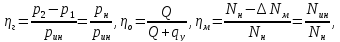 where is the indicator pressure created
in the working chamber of the pump and the corresponding
theoretical head in the blade
pump; - power loss due to friction in the mechanism
pump; - indicator power,