1 Circulation pump installations device and principle of operation
In closed heating systems forced circulation of hot water is required. This function is performed by circulation pumps, which consist of a metal motor or a rotor attached to a housing, most often made of stainless steel. The ejection of the coolant is provided by the impeller. It is located on the rotor shaft. The entire system is driven by an electric motor.
Also in the design of the described installations there are the following elements:
- shut-off and check valves;
- the flow part (usually it is made of a bronze alloy);
- thermostat (it protects the pump from overheating and ensures the economical operation of the device);
- work timer;
- connector (male).
The pump, when installed in a heating system, draws in water, and then supplies it to the pipeline due to centrifugal force. The specified force is generated when the impeller produces rotational movements. The circulation pump will work efficiently only if the pressure it creates can easily cope with the resistance (hydraulic) of the various components of the heating system (radiator, pipeline itself).
How the unit works
The principle of operation of the circulation unit is very similar to the operation of the drainage pump. If this device is installed in the heating system, then it will cause the movement of the coolant due to the capture of liquid from one side and forcing it into the pipeline from the other side
The principle of operation of the circulation unit is very similar to the operation of the drainage pump. If this device is installed in the heating system, then it will cause the movement of the coolant by capturing the liquid from one side and forcing it into the pipeline from the other side. All this happens due to the centrifugal force, which is formed during the rotation of the wheel with the blades. During the operation of the device, the pressure in the expansion tank does not change. If you want to increase the level of coolant in the heating system, install a booster pump. The circulation unit only helps to overcome the resistance force with water.
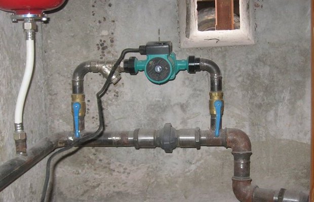
The installation scheme of the device looks like this:
- A circulation pump is installed on the pipeline with hot water coming from the heater.
- A check valve is mounted on the section of the pipeline between the pumping equipment and the heater.
- The pipeline between the bypass valve and the circulation pump is connected by a bypass to the return pipeline.
Such an installation scheme implies the release of the coolant from the device only if the unit is filled with water. In order to keep the liquid in the wheel for a long time, a receiver equipped with a check valve is built at the end of the pipeline.
Circulation pumps used for domestic purposes can develop a coolant speed of up to 2 m / s, and units used in the industrial field accelerate the coolant up to 8 m / s.
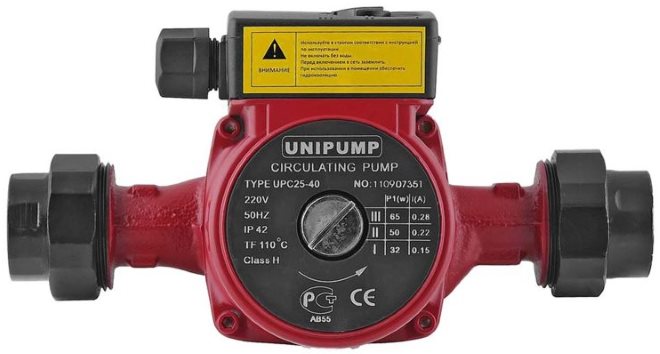
Worth knowing: any kind of circulation pump is powered by the mains. This is a fairly economical equipment, since the engine power for large industrial pumps is 0.3 kW, while for household appliances it is only 85 watts.
Choose a place
When installing such a unit, it is necessary to choose a method for inserting it, taking into account the fact that in the future the device will need to be serviced. In addition to this requirement, there are other points that affect the choice of location for installation.
Previously, it was cut into the return line - so that the working area was washed by already chilled water, and thereby extended the life of the device.Now manufacturers produce pumps with parts and assemblies made of materials that are not afraid of exposure to hot water. Therefore, they can be installed not only in the return, but also in the supply pipeline.
You need to decide where exactly you will embed the device.
To increase the pressure of the coolant, it should be installed on the section of the water supply pipe, placing it closer to the entrance to the expansion tank system. This will ensure that high temperatures are maintained.
Before installing it on a bypass (a jumper, a pipe section between the direct and return supply of the coolant), it is necessary to check whether the device can withstand a strong pressure of hot water.
In the presence of a diaphragm tank, the pump on the bypass is cut into the return pipeline, preferably closer to the expansion tank. When access to the device is difficult, it can be installed on the supply pipeline, and a check valve can also be inserted there.
4 Do-it-yourself schemes and standards for installing pumping equipment
Installation of circulation pumps is carried out in two ways. The first connection scheme of the unit is two-pipe. This connection method is described by a high temperature difference in the system and a variable flow rate of the coolant. The second scheme is single-pipe. In this case, the temperature difference in the heating system will be insignificant, and the carrier flow rate will be constant.
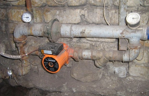
Installed circulation pump
Do-it-yourself connection of the pump is carried out according to the instructions that are attached to the unit. It also indicates the installation procedure for a functional reinforcing chain. Be sure to drain all water from the system before installing the pump. Often there is a need to clean it. During the operation of the heating boiler, a lot of debris is collected on the inner surfaces of the pipes, which worsens the technical performance of the system.
Experts advise placing the circulation unit in front of the boiler - on the return line. This is done in order to eliminate the risk of boiling of an open-type heating system due to the vacuum that is created when the pump is installed at the supply. In addition, if you install the circulation unit on the return, its trouble-free operation will be significantly increased due to the fact that it will operate at lower temperatures.
The procedure for installing the pump itself looks like this:
- You make a bypass (in professional slang - a bypass) in the area where the pump will be placed. The bypass diameter is always taken slightly smaller than the cross section of the main pipe.
- Mount (strictly horizontally) the shaft of the pumping device, place the terminal box on top.
- Install ball valves on both sides of the pump.
- Install a filter. It is not recommended to operate the equipment without this device.
- Place an automatic (optionally manual) vent valve above the bypass line. This device will allow you to clean the air pockets that regularly form in the system.
Further, valves (shut-off) are installed at the inlet-outlet section of the circulation unit. For an open heating system, an expansion tank is additionally required (not installed in closed complexes). The final stage of installation work is the processing of all, without exception, the connection points of various elements of the system with a good sealant.
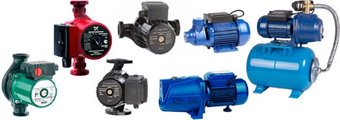
Main varieties
All circulation pumps for heating systems are divided into two design types: devices with a "dry" rotor and circulation pumps with a "wet" rotor.
In circulation pumps of the first type, which is already clear from their name, the rotor does not come into contact with the liquid working medium - the coolant. The impeller of such pumps is separated from the rotor and stator by sealing steel rings, pressed against each other by means of a special spring that compensates for the wear of these elements.The tightness of this sealing assembly during the operation of the pump is ensured by a thin layer of water between the steel rings, which is formed due to the difference between the pressures in the heating system and in the external environment.
Circulation pumps for heating with a “dry” rotor are characterized by fairly high efficiency (89%) and productivity, but hydraulic machines of this type also have disadvantages, including strong noise during operation and difficulty in operation, maintenance and repair. As a rule, industrial heating systems are equipped with pumps of this type; they are rarely used in domestic heating systems.
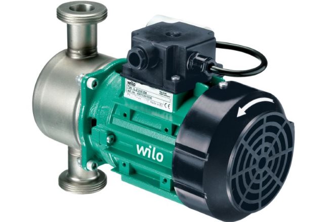
Single-stage circulation pump with a "dry" rotor
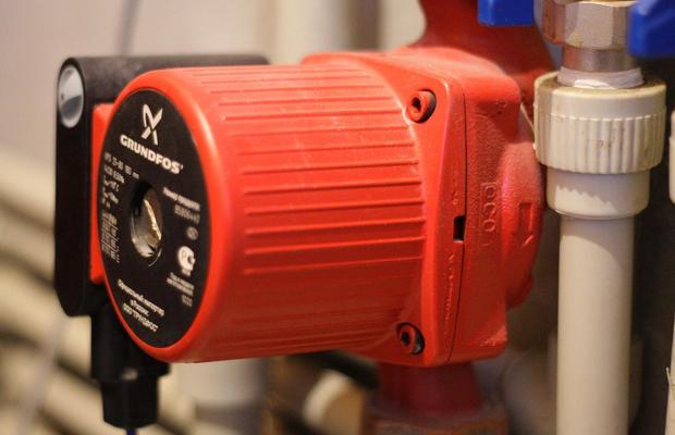
A circulation pump for heating systems equipped with a “wet” type rotor is a device whose impeller and rotor are in constant contact with the coolant. The working medium in which the rotor and impeller rotates acts as a lubricant and coolant. The stator and rotor of pumps of this type are isolated from each other using a special glass made of stainless steel. Such a glass, inside of which a rotor and an impeller rotating in the coolant medium, protects the energized stator winding from the ingress of working fluid onto it.
The efficiency of pumps of this type is rather low and is only 55%, but the technical capabilities of such a device are quite enough to ensure the circulation of the coolant in the heating systems of houses that are not too large. If we talk about the advantages of circulation pumps with a "wet" rotor, then they should include the minimum amount of noise emitted during the operation of such devices, high reliability, ease of operation, maintenance and repair.
Wet circulation pump
Power connection
Circulation pumps operate from a 220 V network. The connection is standard, a separate power line with a circuit breaker is desirable. Three wires are required for connection - phase, zero and ground.
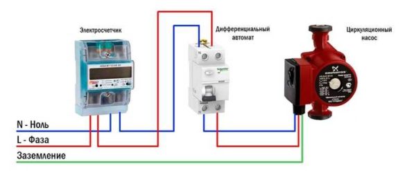
Electrical connection diagram of the circulation pump
The connection to the network itself can be arranged using a three-pin socket and plug. This connection method is used if the pump comes with a connected power cable. It can also be connected via a terminal block or directly with a cable to the terminals.
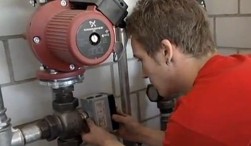
The terminals are located under a plastic cover. We remove it by unscrewing a few bolts, we find three connectors. They are usually signed (pictograms are applied N - neutral wire, L - phase, and "earth" has an international designation), it is difficult to make a mistake.
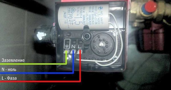
Where to connect the power cable
Since the entire system depends on the performance of the circulation pump, it makes sense to make a backup power supply - put a stabilizer with connected batteries. With such a power supply system, everything will work for several days, since the pump itself and the boiler automation “pull” electricity to a maximum of 250-300 watts. But when organizing, you need to calculate everything and select the capacity of the batteries. The disadvantage of such a system is the need to ensure that the batteries are not discharged.
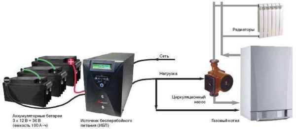
How to connect a circulator to electricity through a stabilizer
Hello. My situation is that a 25 x 60 pump stands right after the 6 kW electric boiler, then the line from the 40 mm pipe goes to the bathhouse (there are three steel radiators) and returns to the boiler; after the pump, the branch goes up, then 4 m, down, rings the house of 50 sq. m. through the kitchen, then through the bedroom, where it doubles, then the hall, where it triples and flows into the boiler return; in the bath branch 40 mm up, leaves the bath, enters the 2nd floor of the house 40 sq. m. (there are two cast-iron radiators) and returns to the bath in the return line; the heat did not go to the second floor; the idea to install a second pump in the bath for supply after a branch; total pipeline length 125 m.How correct is the decision?
The idea is correct - the route is too long for one pump.
Carrying out work
Proper installation of the pump in the heating system of a private house requires performing work, observing certain installation rules. One of them is a tie-in on both sides of the ball valve circulation unit. They may be needed later when dismantling the pump and servicing the system.
Be sure to install a filter - for additional protection of the device.
Usually the quality of the water leaves much to be desired, and particles that come across can damage the components of the unit.
Install a valve on top of the bypass - it does not matter if it is manual or automatic. It is needed to bleed air pockets periodically formed in the system.
Terminals should be directed straight up. The device itself, if it belongs to the wet type, must be mounted horizontally. If this is not done, only part of it will be washed with water, as a result, the working surface will be damaged. In this case, the presence of a pump in the heating circuit is useless.
The circulation unit and fasteners must be placed in the heating circuit naturally, in the correct sequence.
Before starting work, drain the coolant from the system. If it has not been cleaned for a long time, clean it by washing it several times.
On the side of the main pipe, in accordance with the diagram, mount a bypass - a U-shaped pipe section with a pump built into its middle and ball valves on the sides. In this case, it is necessary to take into account the direction of water movement (it is marked with an arrow on the body of the circulation device).
Each fastening and connection must be treated with sealant - to prevent leakage and make the whole structure more efficient.
After fixing the bypass, fill the heating circuit with water and check its ability to function normally. If errors in operation or malfunctions are found, they must be eliminated immediately.
How are circulation pumps arranged?
The circulation pump belongs to the centrifugal type of devices. The mechanism of the unit is enclosed in a case, which can be made of any stainless metal or impact-resistant plastic. The body consists of two halves. On one side there is an electric motor, on the other side there is a chamber for pumping coolant. Chamber cavities are equipped with outlets. They can be threaded or flanged.

The main working unit is an impeller mounted on a ceramic rotor. Rotating from the drive - an electric motor, it creates a directed flow of the working fluid in the pipeline of the heating network. All technical characteristics of the device depend on the design, dimensions, external data of the impeller, its speed of rotation.
Through outlets, the pump is connected to the water line. From one side and the other, the unit is attached to the pipes through a quick coupling. Typically, this connection is a union with a union nut. The flange connection is fastened with four bolts with nuts, flat washers and spring washers. A sealing gasket made of paronite or heat-resistant rubber is installed between the flanges.
ATTENTION! On the connector where the two halves are connected, two drainage holes are made. Condensate is removed through them, accumulating in the stator half of the electric motor.
It is strictly forbidden to close the drainage holes! When installing thermal equipment, it is also necessary to remember that the impeller must be located strictly horizontally as part of the heating system. The pump itself can be installed in any position of the pipeline relative to the horizontal axis. It can be located on a horizontal section of the pipeline, vertical, at any angle to the horizon. But the axis of the impeller must be oriented strictly in the horizontal plane!
3 About the choice of equipment and the rules for its independent calculation
The key indicator that determines the efficiency of the circulation pump is its power. For a domestic heating system, you do not need to try to purchase the most powerful installation. It will only hum strongly and waste electricity.
Mounted circulation pump
You need to correctly calculate the power of the unit based on the following data:
- indicator of hot water pressure;
- section of pipes;
- productivity and throughput of the heating boiler;
- coolant temperature.
The consumption of hot water is determined simply. It is equal to the power of the heating unit. If you, for example, have a 20 kW gas boiler, no more than 20 liters of water will be consumed per hour. The pressure of the circulation unit for the heating system for every 10 m of pipes is about 50 cm. The longer the pipeline, the more powerful the pump must be purchased
Here you should immediately pay attention to the thickness of tubular products. The resistance to water movement in the system will be stronger if you install small pipes
In pipelines with a diameter of half an inch, the flow rate of the coolant is 5.7 liters per minute at the generally accepted (1.5 m / s) speed of water movement, with a diameter of 1 inch - 30 liters. But for pipes with a cross section of 2 inches, the flow rate will already be at the level of 170 liters. Always select the diameter of the pipes in such a way that you do not have to overpay extra money for energy resources.
The flow rate of the pump itself is determined by the following ratio: N/t2-t1. Under t1 in this formula is understood the temperature of the water in the circulation pipes (usually it is 65–70 ° С), under t2 - the temperature provided by the heating unit (at least 90 °). And the letter N indicates the power of the boiler (this value is available in the equipment passport). The pump pressure is set according to the standards accepted in our country and Europe. It is believed that 1 kW of power of the circulation unit is quite enough for high-quality heating of 1 square of the area of a private dwelling.