vortex pumps
Vortex
pumps are used at low flows (0.5
… 40 m3/h)
and high heads (up to 200 m), which in
centrifugal pumps, with the same diameter
wheels, cannot be reached.
They
have the following advantages over
with centrifugal pumps:
—
smaller and cheaper to manufacture;
—
can themselves suck up liquid at start-up
them to work if there is water in the body
pump; little change in feed when changing
pressure.
To the shortcomings
These pumps include:
—
low efficiency of the order of 20 ... 45%;
—
low suction height;
—
the possibility of supplying only clean and not
viscous liquids.
Such
pumps are widely used for pumping
gasoline and kerosene in tank trucks and
stationary filling stations
agricultural water supply
and in public utility installations
and etc.
Basic
design feature of vortex
pumps is moving liquid
media around the periphery of the impeller in
tangential direction, that is
tangent to the circumference of the wheel.
Liquid enters the suction
branch pipe 6 (Fig. 4), and to
worker
wheel, which represents a disk with
straight blades around the circumference of the wheel.
Rotating impeller 1 particle
liquids in cells
rotate together with the wheel and due to
friction drags fluid particles,
located in the annular channel,
covering the impeller. Simultaneously
particles between the blades acts
centrifugal force and they are ejected
into the annular channel, and then again fall
on the wheel, making a vortex motion,
indicated by the arrow in Figure 4. Thus
way, the vortex of fluid particles
moves from the suction pipe to
pressure and, resting on the jumper,
located between the nozzles, under
high pressure is thrown into the pressure
pipe branch.
Characteristic
vortex pump is shown in the figure
5.
V
difference from centrifugal pumps power
for peripheral pumps with increased flow
falls.

Rice.
1.4. Characteristics of the vortex pump

Rice.
1.5. Characteristics of the vortex pump
Rules
vortex pump start
1.
Fill the pump body with water.
2.
Open latch.
3.
Start.
4.
Close the valve until
operating mode.
CONTROL
QUESTIONS
-
Specify
reason
causing cavitation? -
What kind
exists
ways
fighting cavitation? -
explain
principle
centrifugal work
(vortex) pump. -
How
determine the pump head,
created
on this pumping station? -
How
set pump operating mode? -
decipher
brand of pumps 3K6;
K45/50;
KM-20/30. -
Which
the pump is started with the valve open,
and which one when closed and why?
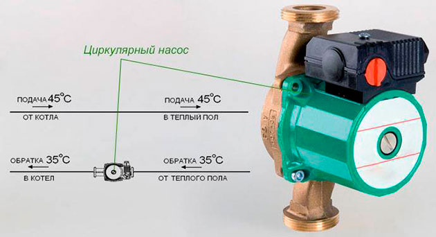
Pump designation on the water supply diagram
GOST 21.205-93 provides a symbol for manual, jet and centrifugal pumps. The latter are the most popular - according to this principle, booster and circulation units installed inside buildings, most outdoor water intake devices work.
However, this designation, in accordance with GOST 21.205-93, does not cover the entire range of pumping units, for example, vibration, screw and vortex electric pumps are also used to supply water from wells or wells.
More detailed information and graphic images of pumps (hydraulic machines) are given in GOST 2.782-96 ESKD, the main provisions of the standard:
- The designations show the purpose of the device, the principle of its operation and external connections.
- The graphic image does not display the design of the element.
- Alphabetic characters do not provide information about product parameters and their values.
- The State Standard does not establish the size of the designations, as well as their location, if the meaning of the connections is not distorted.
Graphic images of hydraulic machines (electric pumps and engines) are divided into the following groups:
- on functional grounds;
- according to the principle of action;
- on the relationship between the direction of rotation of the actuators, the movement of the flow of the working medium and the location of the control devices.

Rice. 14 Display of some types of hydraulic machines by functional features (GOST 2.782-96 ESKD)
Varieties of water floor pumps and their parameters
Determining the pump label
When choosing a circulation pump for a warm water floor, you should know that the marking applied to it is of great help. It is affixed immediately below the model name and looks like two numbers written through a dash. For example: 32 - 60.
The first is the connection size, 32 mm (or 1” ¼). Usually, a pump for a warm water floor is supplied complete with union nuts for its installation / dismantling. This is their size.
The second informs about the height to which the pump can supply water. In this case, it is equal to 6.0 m of water. Art. (0.6 atm.). There are models that are designed for larger and smaller values of the specified indicator.
A pump for a water floor is selected taking into account the results of a preliminary hydraulic calculation of CO with underfloor heating. Information about the magnitude of the load at the given parameters is applied to the body of the product.
The pump for a warm water floor is made with three switching modes, differing in performance (i.e., the amount of liquid that the pump is able to pump per hour).
The third is max performance. In each of these positions, the pump consumes current, the value of which is placed on the plate.
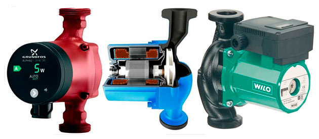
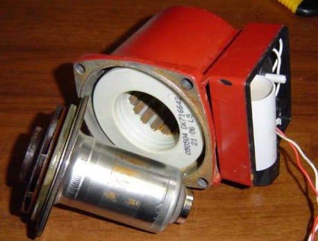
Types of pump designs
By their design, the circulation pump for a warm water floor of any model practically does not differ from each other, except for the appearance and control. The German pumps manufactured by Grundpos and Wilo have proven to be the most reliable. The latter are more affordable. The above pumps belong to the household series, which are installed in residential premises and private houses.
In addition, there is a pump for a water floor for industrial use. Their main difference is that they are double and are fixed not with nuts, but with special flanges, the diameter of which exceeds 50 mm.
There are also models such as a pump for a warm water floor with a thermostat.
Pumps positioned as underfloor heating products have a three-way valve. When choosing this option, it should be borne in mind that valve designs are not equivalent in terms of their performance. Some of them have the indicated indicator, which does not exceed 2.5 cubic meters / hour, which does not allow them to work normally if the floors are laid on an area of more than 50 square meters. besides, they are not adjustable. Therefore, you can install them only if you have a pump for a warm water floor of a small volume.
There are valves with adjusting devices that are controlled in manual mode and a special servo drive in automatic mode. Their flow rate is 4.0 cubic meters per hour and they work on areas up to 150 sq.m.
Why do we need drawings and diagrams
Usually, in dachas and in individual houses of a small area without complex heating systems with underfloor heating and a large number of radiators, with a small number of plumbing fixtures, the installation of utilities is carried out without special standardized drawings. However, in this case, they are necessary even in a simplified form in order to correctly calculate the amount of materials, fittings, valves, and determine the upcoming financial costs. The availability of drawings (design documentation) from specialized design organizations at the customer's site provides the following advantages:
Usually, the drawing up of schemes is accompanied by hydraulic calculations by qualified engineers using computer programs - this allows you to use communications with the greatest efficiency. When heating, the correct calculation and installation of the system according to the scheme will reduce the cost of fuel for heating the coolant. When carrying out after installation any type of preventive, repair work, according to the scheme, you can quickly find the location of the problem node with the exact coordinates
This is very important if damage to the pipeline, breakage of its fragments occurred under the screed or plaster on the walls, in hard-to-reach places. Rice
2 Water supply and sewerage plan in accordance with GOST 21.601-79 The presence of design documentation with preliminary calculations developed by specialists will help to avoid gross errors during the installation of communications - the wrong choice of diameter and material of pipelines, the power of circulation and centrifugal pumps, incorrect slope angles, erroneous wiring of radiator heat exchangers and others. Installation of communications according to the schemes of developers of architectural and construction organizations will increase the comfort of living. With correct thermal calculations, the temperature in the residential premises will be optimal, odors from the sewer will not enter the house, the volumes of cold and hot water will always be enough to fully meet the needs of all residents, septic tanks will not have to be emptied every week, water from storm drains and precipitation will not accumulate on the site . The presence of a scheme is vital for carrying out installation work by hired specialists from construction organizations in the absence of an owner giving instructions. Also, carrying out all the work according to the drawings in the event of any problems will allow you to find the culprit in the face of builders or developers. In this case, the customer will have in his hands irrefutable evidence for the presentation of financial claims.

Rice. 3 Varieties of schemes
How circulation pumps are labeled
Usually, in the marking of circulation pumps for heating systems, manufacturers enter the main characteristics and data that make it possible to judge the use of devices. Consider, using the example of a Grundfos pump, how these devices are labeled.
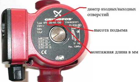
Marking of the Grundfos circulation pump
Control type
The first letters correspond to the device type. In our case, "UP" indicates the circulation type of the device. Next comes the designation of the control method. There are several options:
- constant engine speed;
- speed switching (S);
- stepless speed control with a frequency converter (E).
Interesting to know. With a built-in frequency converter, you can set any speed of the electric motor and thereby select the optimal pump performance for a particular system.
Pipe diameter and head
After the letters in the marking there are numbers, the first of which indicates the inner diameter of the nozzles in millimeters, and the second shows the maximum pressure in decimeters.
Before installing the device in the pipeline, it is necessary to take into account the diameter of the inlet and outlet pipes. Of course, with the help of special adapters, you can install the device on a pipe of a different size, but in this case it will not be able to give out the characteristics that were laid down by the manufacturer, which will significantly reduce the efficiency of the device.
Installation length
The next (third) number indicates the installation length in millimeters. Like the diameter of the nozzles, this indicator is important for installing the device in the pipeline system. It is especially important in the case of a pump tie-in, where every millimeter plays a decisive role.

Knowing the installation length greatly simplifies the process of inserting the device
Different manufacturers may indicate additional data in the labeling of heating circulation pumps.which they consider important in choosing the right model. For example, the type of housing design, the method of pipe connection, the class of electricity consumption, etc.
Model range of STsL units
In the "Pumps" category of the company's product catalog, you can find the following units: ASCL, pumps STsL 20/24, 00A, STsL 00 pump, STsN 75/70, etc. Let's consider the most popular models and their technical characteristics.
Main characteristics
STsL-00 is a left-hand rotation unit with two stages, the first of which provides water (gasoline) suction, the second creates pressure. The centrifugal vortex pump is installed on a fuel truck, water dispensing installations. The centrifugal impeller STsL-00 of the pump is made of cast iron. The pressure reaches 30 m, self-priming - 6 m. The performance indicators are high - 30 cubic meters / hour.
The shaft rotates at a speed of 1500 rpm. It is completed with a reducer on agricultural machines for watering livestock, pumping water when extinguishing fires and watering machines. The purpose of the STsL-00 pump gearbox is to drive the unit from the power shaft of a tractor vehicle, increasing the gear ratio by 3.22 times.
Spare parts for STsL pump
00A is a self-priming two-stage mechanism installed on refuellers, tank truck chassis. The cantilever pump of horizontal installation is developed in two versions: the first version is left rotation (mounted on ZIL, GAZ trucks, MTZ tractors, the second version is right rotation for installation on KamAZ, KrAZ trucks). The rotational speed is 1500 rpm. Feed - 21.6 cubic meters / h, pressure - 30 m, suction height is 4.5 m.
The pump is driven by the machine (tractor) engine, through the power take-off, intermediate transmission. For stationary installation, an explosion-proof electric motor is used, the power of which is close to 5.5 kW. Flow-through accuracy execution material: body made of cast iron, impeller made of aluminum alloys, centrifugal wheel made of cast iron.
Self-priming electric pump 1STsL-20-24G is a device that pumps neutral liquids with a viscosity not exceeding 2 ∙ 10-5 sq. m / s and temperature value - from -40 to +50 degrees. The operation of the pump 1STsL 20 24G takes place in a temperate climate. Available in left-right rotation.
Duration of suction - 50 s. Power varies in the range of 16-24 kW. The efficiency is - 33%. Head length - from 45 m at 1700 rpm. up to 54 m at a speed of 1450 rpm. Feed - 32-45 cubic meters / h. Self-priming height exceeds 5 m.
Pumps STsL 20/24 are horizontal, two-stage, centrifugal-vortex units used for pumping clean liquids. Stage 1 - centrifugal mechanism, equipped with a closed impeller, a spiral branch of a circular cross section. It provides high cavitation qualities. Stage 2 - a vortex mechanism with a closed wheel, as well as an open channel, thanks to which there is a high pressure.
The pump is aggregated with an electric motor into the ASCL-20 device. Operates in tropical or temperate climates. Liquid supply - 35-45 cubic meters / min. The head is from 45 to 54 m. The self-priming height is 5.5 m. The power of the STsL 20/24 pump is 15.5-24 kW. Rotation - "by order of the consumer", left / right. The drive is electric. Max. flow rate - 32 cubic meters / h.
Types of schemes
A scheme in design documentation is a document in which the symbols of the main elements of communications or parts of products, equipment, as well as the connection (connection) between them are shown graphically. Their distinguishing feature in comparison with the drawings is the lack of image scale and correspondence to the real spatial arrangement of elements.
The types and types of schemes are regulated by GOST 2.701-84, the most famous of them, commonly used in individual housing construction:
- Electrical.
- Hydraulic.
- Energy.
- Gas.
- Combined.
According to the purpose, the schemes are divided into the following categories:
Structural. A structural or block diagram shows the main components of the product, their purpose and interconnections, reveals the functioning algorithm. Parts of a system or devices are depicted as inscribed in rectangles, rhombuses or other shapes, connected by lines with arrows indicating relationships.
Developed early in the design of a product or system, useful for learning how it works.
Functional. They reveal the processes occurring in the system, a specific product or its individual nodes. They are necessary to determine the principle of operation, technical parameters of products, they are used in the adjustment, adjustment, repair, control of the physical parameters of the working environment and equipment.

Rice. 4 Sewerage schemes in the drawings in accordance with GOST 21.601-79 - examples
Fundamental
connections. Wiring diagrams show the connections between individual nodes or parts of systems, simple products, complex technical equipment. Establish laying methods and methods of connecting system elements, connection points with indication of entry and exit points of joined fragments.
Connections. The diagrams show the connection of external communications, products, equipment to system devices. Reveal the type of connections with indication of their technical characteristics.
Are common. They show the main system nodes and the connections between them in relation to specific installation conditions, they are tied to the equipped objects of various types.
Locations. Specifically, they show the placement of various communication nodes and equipment relative to objects and each other, indicating distances in units of length.
Each scheme in the drawing corresponds to its own alphabetic and numeric marking marks, regulated by GOST 2.701-84.
Of the listed list, the most complex and detailed are the schematic diagrams, most often used in the design of various systems and equipment.

Rice. 5 Designation of the filter and elements of general use in accordance with GOST 21.205-93
Brand Importance
Modern manufacturers of devices for the circulation of coolant in the heating system offer almost identical characteristics of their products. The main differences relate to reliability and uptime. That is why many experts advise to overpay a little and give preference to a well-known brand.
For your information. To date, the aforementioned Grundfos, Willo, Speroni, Wester and Elso-Therm are considered the most reliable companies.
In addition, there are a large number of Chinese options (fakes), the quality of which, to put it mildly, leaves much to be desired. Of course, in this case, you can save a lot, but even the seller of the goods can hardly guarantee that the marking matches the actual characteristics of the circulation pump.
The low price should not attract, but scare away the buyer, otherwise you will have to remember your repair skills very soon
To avoid problems with poor-quality pump operation, which is caused by cheap equipment, calculation errors or incorrect installation, it is better to immediately entrust the organization of the home heating system to specialists.
1 Water floor heating system how it works
The system includes the following mandatory components:
- heat source (boiler, central heating riser);
- coolant (water, antifreeze, oil, etc.);
- heating pipes;
- insulation;
- control and distribution device;
- circulation pump.
The coolant circulates through an extensive network of pipelines located on the floor under the coating. The heat source is usually a gas boiler.
The use of water floors in apartments with a heat source supplied centrally through the riser is allowed in houses with apartment-by-apartment horizontal heating distribution.

Underfloor heating scheme
For the purpose of equal heating of the floors, the pipes are placed at a small distance between them (100-200 mm). At the walls, the distance between the pipes is left less than in the center of the room. Pipe laying is carried out according to two schemes:
- snake - associated with the slalom or zigzag track;
- snail - resembles a spiral.
An example of calculating the pump power for a warm floor
If you have a parallel connection
The calculation of the pump for underfloor heating in this case should begin with the calculation of the recommended flow rate for each branch and summarize the results.
Calculate the total amount of losses in all circuits (branches). This will help determine the constant flow in the mixing unit. As a rule, this value ranges from 40% to 100% of the total circuit costs. That is, with a total flow rate of the circuits of 15 l / min, the flow rate for incoming heat will be equal to 6 - 15 l / min.
Its value is influenced by:
- The difference between the input temperature and the one set by the thermal head;
- Floor heat loss.
Example. The boiler delivers a coolant heated to 60 degrees. The mixing unit is set to 40 degrees. We get an expense of 40%. At the feed 75 degrees, at the node - 40 degrees. Consumption - 25%.
The bypass (if any) must be taken into account in the calculations. and it has a constant flow. Therefore, we add about 6 l / min to it. In long pipes, there is more heat loss, which causes the thermal head to increase the heat transfer, the flow increases and the pressure drops.
If you have a serial connection
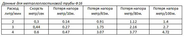
The calculation of the pump for underfloor heating in this case is performed as follows. The recommended consumption is calculated for all branches, the results are summarized. The resulting value is compared with the available graph No. 3, according to which the head loss is determined.
You can build this graph yourself for your pump. The curve for all models is standard. Based on the pressure obtained, the required pipe length is selected from the table.
Conclusion: The pump head according to the third graph should be higher than the head loss in the entire length of the laid floor pipes with a known flow rate for each circuit. The pressure loss in each circuit is determined from the table below.
The actual head of the installed pump is determined from the third graph to determine the total flow of the installed mixing unit.
It is important to take into account one more information. In the event that instead of water you poured antifreeze or another similar liquid into the system, then you should take into account the difference in viscosity, which can reach 30 - 50 percent
Which will lead to an even greater slowdown in the movement of the coolant through the pipes. Therefore, other calculations are required.
In this case, the pump power should be increased by at least 20% (option, by the same 20% make the pipes shorter). The heat capacity of antifreeze is about 20% less than that. which water has. Accordingly, it will move heat by the same amount less.
Article rating: (total 1 votes, rating: 5.00 out of 5)
In order for the installed heating radiator to be fixed correctly and securely, it is necessary to select the desired fasteners.
Varieties of heat-reflecting screens and their advantages
Considering the topics of screens for heating radiators, most often they mean screens that perform decorative and protective functions.
Private house heating security system
The main task that the home heating security system is designed to solve is to protect the heating system from the appearance of air congestion in the lines and excessive pressure.
Rules for starting centrifugal pumps
Pump
cannot be launched without prior
examination, which should, as a rule,
carried out before each start.
At
Inspection should check:
-
Available
Is there grease in the bearing housing. -
Not
whether there are jams in the pump, which is checked
turning the shaft by the clutch by hand. -
Good
whether the stuffing box is stuffed.
Stuffing box
must be carefully stuffed and evenly
weakly under
pull so that when working
pump water through the stuffing box slowly
dripped.
seepage
water through the stuffing box indicates good
padding, as well as the fact that air through
the stuffing box does not leak into the pump.
After
after making sure that the pump is working,
necessary:
-
close
valve on the discharge pipeline,
what is needed to avoid
motor overload, during
pump start. -
Pour
liquid into the suction pipe
and pump housing. -
Turn on
electric motor. -
By
reaching full speed
pump open the valve before receiving
the required pressure (according to the indication
pressure gauge on the discharge pipeline).
Note:
Not recommended to avoid overheating
work for a long time with the valve closed.
The main types of hydraulic communications of a private house
In order for an individual house to become habitable, various types of communications are brought to it, the main ones are: water supply, electricity and sewerage, if possible, gas is connected from gas pipelines.
When drawing up schemes, household systems of private houses using water are conditionally divided into the following categories:
- Internal plumbing supply hot and cold water. It includes pipes made of metal and polymer materials, control and shut-off valves, coarse and fine filters, electrical equipment and appliances, water outlets for connecting plumbing.
- Internal sewerage. Its main nodes are the riser, the fan pipeline and ventilation, as well as the pipeline extending from plumbing fixtures: toilets, sinks and sinks, bathtubs and showers.
- Communications of the heating system. The heating main includes a heating boiler and a pipeline circuit that transports the coolant to the heating radiator or itself is a heat exchanger in underfloor heating. Also, the closed-type system includes a large number of sanitary fittings and hydraulic equipment - a circulation electric pump, an expansion tank, thermostats and air vents, pressure gauges.
- External water supply networks. In the absence of a centralized pipeline, water is taken from wells and wells. In this situation, due to the ease of installing pipes in borehole caissons and wells, laying them underground into the house, the scheme is not so important and it is quite possible to do without it.
- External communications storm and sewerage. Fecal effluents from an individual house in the absence of a centralized sewer line are diverted to septic tanks and then to drainage wells or aeration fields. Storm sewer pipes are usually laid underground and taken out of the site or placed in a drainage pit.
In some cases, if the wiring is too complicated and work is carried out in the absence of the owners, the schemes for laying sewer external pipelines with an indication of the dimensional parameters may well come in handy.

Rice. 6 Display of flow directions, communication lines, regulation and drives
—
CAUTION 1
ÐбознаÑÐµÐ½Ð¸Ñ Ð½Ð°ÑоÑов Ð Ð Ð Ð Ð Ð Ð Ð Ð ² Ð Ð Ð Ð Ð Ð Ð Ð Ð Ð Ð Ð Ð Ð Ð Ð Ð Ð Ð Ð Ð Ð Ð Ð Ð Ð Ð Ð Ð Ð Ð Ð Ð Ð Ð Ð Ð Ð Ð Ð Ð Ð Ð Ð Ð Ð Ð Ð ñññññ¼²ñ¶¶¶¶½½½¸¸¸¸¸¸¸¸¸¸¸¸ Run. Ð ð Ð Ð Ð Ð Ð Ð Ð Ð Ð Ð Ð Ð Ð Ð Ð Ð Ð Ð Ð Ð Ð Ð Ð Ð Ð Ð Ð Ð Ð Ð Ð Ð Ð Ð Ð Ð Ð Ð Ð Ð Ð Ð Ð ² РРРРРРРРппаÑаÑовданной Ð Ð Ð Ð Ð Ð Ð Ð Ð Ð Ð Ð Ð Ð Ð Ð Ð Ð Ð Ð Ð Ð Ð Ð Ð Ð Ð Ð Ð Ð Ð Ð Ð Ð Ð Ð Ð Ð Ð Ð Ð Ð Ð Ð Ð Ð Ð Ð Ð Ð Ð Ð Ð Ð Ð Ð Ð Ð Ð Ð ² Ð μ конÑÑÑÐ ° ÑимвоР»Ð °, Ð ° ÑÐμгÑл иÑÑÐμмоÑÑÑ Ð¿Ð¾Ð'Ð ° Ñи - Ð'Ð »Ð¸Ð½Ð½Ð¾Ð¹ Ñонкой ÑÑÑÐμл кой, пÐμÑÐμÑÐμкР° ÑÑÐμй ÑÑÐ¾Ñ ÐºÐ¾Ð½ÑÑÑ Ð¿Ð¾Ð' ÑгР» R¾Ð¼.
a
наÑение наÑоÑа РРРРРРРРРРРРРРРРРРРРРРРРРРРРРРРРРРРРРРРРРРРРРРРРРРРРРРРРРРРРРРРРРРРРРРРРРРРРо РРРРпÑи п 3000 об / мин.
a
наÑение наÑоÑа Ð ° Ð ½Ð °Ð Ð Ð Ð Ð Ð Ð Ð Ð Ð Ð Ð Ð Ð Ð Ð Ð Ð Ð Ð Ð Ð Ð Ð Ð Ð Ð Ð Ð Ð Ð Ð Ð Ð Ð Ð Ð Ð Ð Ð Ð Ð Ð Ð Ð Ð Ð Ð Ð Ð Ð Ð Ð Ð Ð Ð Ð Ð Ð Ð Ð Ð Ð Ð Ð Ð Ð Ð Ð Ð Ð Ð Ð Ð Ð Ð Ð Ð Ð Ð Ð Ð Ð Ð Ð Ð Ð Ð Ð Ð Ð Ð Ð Ð Ð μññññºº
a
наÑение наÑоÑа ² ²Ð Ð Ð Ð Ð Ð Ð Ð Ð Ð Ð Ð Ð Ð Ð Ð Ð Ð Ð Ð Ð Ð Ð Ð Ð Ð Ð Ð Ð Ð Ð Ð Ð Ð Ð Ð Ð Ð Ð Ð Ð Ð Ð Ð Ð Ð Ð Ð Ð Ð Ð Ð Ð Ð Ð Ð' з коÑоÑÑÑ — подаÑа наÑоÑа Q, м3 / Ñ, вÑоÑое — Ð½Ð°Ð¿Ð¾Ñ Ð, м. жидкоÑÑи.
a
наÑоÑов ЦРР° Ð Ð Ð Ð Ð Ð Ð Ð Ð Ð Ð Ð Ð Ð Ð Ð Ð Ð Ð Ð ÐμÐ Ð Ð Ð Ð Ð Ð Ð Ð Ð Ð Ð Ð Ð Ð Ð Ð Ð Ð Ð Ð Ð Ð Ð Ð Ð Ð Ð Ð Ð Ð Ð Ð Ð Ð Ð ° Ð ±) Ð'ðð¾ðμμμμμμμμμðμμμμμ½½½½ð ½ð½Ð1Ð Ð Ð Ð Ð Ð Ð Ð Ð Ð Ð Ð Ð Ð Ð ñ Ð Ð Ð Ð Ð Ð Ð Ð Ð Ð Ð Ð Ð Ð Ð Ð — номиналÑнÑй Ð½Ð°Ð¿Ð¾Ñ Ð² м ÑÑ. bridle; Ð ²) Ð Ð Ðμ Ð Ð Ð Ð Ð Ð Ðμ Ð Ð Ð Ð Ð Ð Ð Ð Ð Ð Ð Ð Ð Ð Ð Ð Ð Ð Ð Ð Ð Ð Ð Ð Ð Ð Ð Ð Ð Ð Ð Ð Ð Ð Ð Ð Ð Ð Ð Ð Ð Ð Ð Ð Ð Ð Ð Ð Ð Ð Ð Ð Ð Ð Ð Ð Ð Ð Ð Ð Ð Ð Ð Ð Ð Ð Ð Ð Ð Ð Ð Ð Ð Ð Ð Ð Ð Ð Ð Ð Ð Ð Ð ñооð𸸸¸¸¸¸¸¸ г) Ðμ Ð Ð Ð Ð Ð Ð Ð Ð Ð Ð Ð Ð Ð Ð Ð Ð Ð Ð Ð Ð Ð Ð Ð Ð Ð Ð Ð Ð Ð Ð Ð ° Ð Ð Ð Ð Ð Ð Ð Ð Ð Ð Ð Ð Ð Ð Ðμ Ð Ð Ð Ð Ð Ð Ð ÐμÐ Ð Ð Ð Ð Ð Ð Ð Ð Ð Ð Ð Ð Ð Ð Ð Ð Ð Ð Ð Ð Ð Ð Ð Ð Ð Ð Ð Ð Ð Ð Ð Ð Ð Ð Ð Ð Ð Ð Ð Ð Ð Ðμ влениÑ.
a
R обознаÑение наÑоÑов ÑпмоÑнением вводиÑÑÑ Ð±Ñква напÑимÐÐµÑ Ð¥Ð — ( ¥¥Ð — ( ¥¥Ð, Ð¥Ð
a
|
4-8. a |
R обознаÑение наÑоÑа кÑоме бÑкв вÑодÑÑдве гÑÑÐ¿Ð¿Ñ ÑиÑÑ. РРРРРРРРРРРРРРРРРРРРРРРРРРмð Ð Ð Ð Ð μ Ð Ð ¼ Ð Ð Ð Ð Ð Ð ¼ Ð Ð Ð Ð ¼ Рм Ð ° ÑиÑÑÑ Ð¿Ð¾ÑÐ »Ðμ Ð ± Ñкв - коÑÑÑиÑиÐμÐ½Ñ Ð ± ÑÑÑÑоÑоÐ'ноÑÑи, ÑмÐμнÑÑÐμннÑй в 10 ÑÐ ° Ð · и окÑÑгл ÐμннÑй Ð'о ÑÐμÐ »Ð¾Ð³Ð¾ ÑиÑл Ð ° .
a
|
ÐбÑий вид. a |
R обознаÑение наÑоÑа. Ðððð Ðμ Ððñððμк ° °Ð¼Ð¼ÐμðÐμμμºººººðððμºººº Ðμμнððððμμðððððððð50505050 ÐðÐððо РоР· 69) ¸Ðµ RÐСТа. ÑабÐ". 2.2.
a
|
ÐððððÐðÐð Ð Ð Ð Ð Ð Ð Ð Ð Ð Ð Ð Ð Ð Ð Ð Ð Ð Ð Ð Ð Ð Ð Ð Ð Ð Ð Ð Ð Ð Ð Ð Ð Ð Ð Ð Ð Ð Ð Ð Ð Ð Ð Ð Ð Ð Ð Ð Ð Ð Ð Ð Ð Ð Ð Ð Ð Ð Ð Ð Ð Ð Ð Ð Ð Ð Ð Ð Ð Ð Ð Ð Ð Ð Ð Ð Ð Ð Ð Ð Ð Ð Ð Ð Ð Ð Ð Ð Ð Ð Ð Ð Ð Ð Ð Ð Ð Ð Ð Ð Ð Ð Ð Ð Ð Ð Ð Ð Ð Ð ° Ð Ð ñð¸ðððð | | | |ððð¿¿¿¿¿¿¿ð¿¿¿¿¿¿¿¿¿¿¿¿ Ð Ð Ð Ð Ð Ð Ð Ð Ð Ð Ð Ð Ð Ð Ð Ð Ð Ð Ð Ð Ð Ð Ð ¿Ð Ð Ð Ð Ð Ð Ð a |
R обознаÑение наÑоÑа вÑодÑÑÑÑдве
a
R обознаÑение наÑоÑа вÑодÑÑÑÑдве
a
R обознаÑение наÑоÑа Ð ²ñðððññññ ¸ññððððððв¸ñññμμññвÐðÐðнμÐðвÐðÐðнÐμÐðÐ Ðð °ÐðÐμÐμÐμÐμÐμÐμðÐμ ñññμμμ½½ ¹¹ ² ² 25 α Ð · бÑква - Ñип наÑоÑа; Ðμ Ð Ð Ð Ð Ð Ð Ð Ð Ð Ð Ð Ð Ð Ð Ð Ð Ð Ð Ð Ð Ð Ð Ð Ð Ð Ð Ð Ð Ð Ð Ð Ð Ð Ð Ð Ð Ð ñ Ð Ð Ð Ð ² 10 α Ð Ðμ Ð ² 10 ñÐ °ñ³³³³³³¹....
a
Marking of centrifugal pumps
The industry produces a huge number of different types of centrifugal pumps. In factories, they can be mass-produced or by personal orders.There is a huge number of pumps in operation, marked according to old regulatory documents. We give the marking - both old and new pumps.
The marking of centrifugal pumps should be known when designing a pumping unit, during the operation of a pumping unit, when a pump fails and is replaced with a new one, etc. Currently, there is no unified marking methodology. When marking, capital letters, a combination of capital letters, lowercase letters, numbers and a combination of numbers are used. Former brands of centrifugal pumps, for example, included: - numbers indicating the diameter of the inlet pipe in mm, reduced by 25 times and rounded; - lowercase letters indicating the type of pump; - numbers after letters and a hyphen, denoting the speed factor ns, reduced by 10 times; - numbers after the multiplication sign, indicating the number of stages in multistage centrifugal pumps.
Let's give examples. Pump 4K-6 is a cantilever pump, the diameter of the absorbing pipe of the pump is 100 mm, the speed factor is ns = 60. The pump 10M-8x6 is a multistage pump, the diameter of the absorbing pipe is 250 mm, the speed factor is ns = 80, the number of stages is 6. Pump 12D -13 - double-sided centrifugal pump type D, the diameter of the absorbing pipe is 300 mm, the speed coefficient ns = 130.
For pumping chemically brutal water, pumps are used, the working bodies of which are made of materials that are resistant to the effects of pumped water. For this type of pumps, the following letter designations are used: X - chemical console on a separate rack; AX - chemical cantilever for pumping water with hard inclusions; HG - chemical sealed monoblock with an electric motor; HP - chemical submersible; HPA - chemical submersible for pumping water with hard inclusions; PCP - chemical submersible with outriggers. For example, 4X-6E-1 is a centrifugal chemical pump, single-stage, with parts in the flow part of the pump made of chromium-nickel-molybdenum steel, the diameter of the absorbing pipe is 100 mm, the speed coefficient ns = 60.
In the marking of centrifugal pumps, the following designations will soon be used: lowercase letters indicating the type of pump; numbers after the letters indicating the pump flow Q, m3/h; numbers after the slash or after the hyphen, indicating the pump head H, m. For example, the K20 / 30 pump is a cantilever centrifugal pump with a flow Q = 20 m3 / h, a head H = 30 m.
In the marking of centrifugal pumps, the following large letters and their combinations are more often used: K - cantilever, N - oil, KM - cantilever monoblock, TsN - centrifugal, CNS - centrifugal sectional, PTSN - food centrifugal, PE - nutritious, Ks - condensate, F - fecal, SM - fecal, D - horizontal double-sided entrance, V - vertical, ETsV - centrifugal for lifting water, driven by an electric motor, etc.
Lowercase letters indicate the following: B - high-pressure, C - medium-pressure, X - chemical, A - 1st option for turning the impeller, B - 2nd option for turning the impeller, etc.
The centrifugal pump can be connected to different types of electric motor, for example, the K20/30 pump can be connected to 4 types of electric motors. The question of marking electric motors can be found in the special literature on pumps. The issue of labeling centrifugal pumps manufactured by companies from different countries can be resolved only after familiarization with the regulatory documentation of these companies. Thus, the decoding of the marking of the pump (pumping unit) can be performed using the passport of the pump (pumping unit), the corresponding GOST and special literature.
Rubric: Industrial pumps | Tags: pump, pump, pumps