How to find out the pump flow rate
The calculation formula looks like this: Q=0.86R/TF-TR
Q - pump flow rate in m3 / h;
R - thermal power in kW;
TF is the temperature of the coolant in degrees Celsius at the inlet to the system,
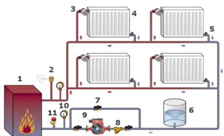
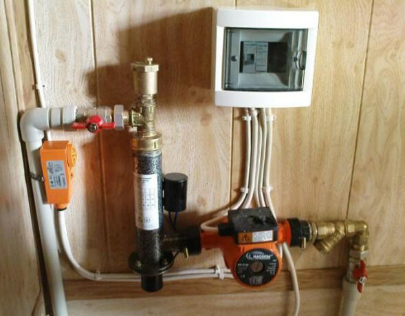
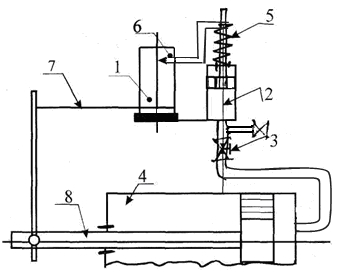
Layout of the heating circulation pump in the system
Three options for calculating thermal power
It may be difficult to determine the thermal power index (R), so it is better to focus on generally accepted standards.
Option 1. In European countries, it is customary to take into account the following indicators:
- 100 W/sq.m. - for private houses of a small area;
- 70 W/sq.m. - for high-rise buildings;
- 30-50 W/sq.m. - for industrial and well-insulated residential premises.
Option 2. European standards are well suited for regions with a mild climate. However, in the northern regions, where there are severe frosts, it is better to focus on the norms of SNiP 2.04.07-86 "Heat networks", which take into account outdoor temperatures up to -30 degrees Celsius:
- 173-177 W/sq.m. - for small buildings, the number of storeys of which does not exceed two;
- 97-101 W/sq.m. - for houses from 3-4 floors.
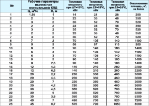
Option 3. Below is a table, according to which you can independently determine the required thermal power, taking into account the purpose, degree of wear and thermal insulation of the building.
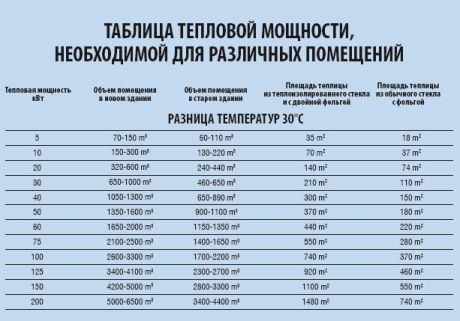
Table: how to determine the required heat output
Formula and tables for calculating hydraulic resistance
Viscous friction occurs in pipes, valves and any other components of the heating system, which leads to losses in specific energy. This property of systems is called hydraulic resistance. There are friction along the length (in pipes) and local hydraulic losses associated with the presence of valves, turns, areas where the diameter of the pipes changes, etc. The hydraulic resistance indicator is denoted by the Latin letter "H" and is measured in Pa (Pascals).
Calculation formula: H=1.3*(R1L1+R2L2+Z1+Z2+….+ZN)/10000
R1, R2 denote pressure losses (1 - supply, 2 - return) in Pa / m;
L1, L2 - the length of the pipeline (1 - supply, 2 - return) in m;
Z1, Z2, ZN - hydraulic resistance of the system nodes in Pa.
To facilitate the calculation of pressure losses (R), you can use a special table that takes into account possible pipe diameters and provides additional information.
Table for determining pressure loss
Averaged data on system elements
The hydraulic resistance of each element of the heating system is given in the technical documentation. Ideally, you should use the characteristics indicated by the manufacturers. In the absence of product passports, you can focus on approximate data:
- boilers - 1-5 kPa;
- radiators - 0.5 kPa;
- valves - 5-10 kPa;
- mixers - 2-4 kPa;
- heat meters - 15-20 kPa;
- check valves - 5-10 kPa;
- control valves - 10-20 kPa.
Information on the hydraulic resistance of pipes made of various materials can be calculated from the table below.
Table of pressure losses in pipes
1 Initial data for calculating the impeller.
Working
the wheel is the most important element
centrifugal pump. If there is
the need for analytical calculation
pump, as in our case, then the calculation
carried out taking into account the geometry earlier
designed pumps with high
energy indicators.
For
calculation of the impeller is necessary
know the Q feed,
head H, speed n.
When designing a fire pump n
take equal to 2900 rpm, which provides
rational wheel design,
developing a sufficiently high pressure.
At the same time, the restrictions on the rotation frequency,
associated with the risk of cavitation,
absent, because fire pumps on
courts work with backwater.
For
estimates of the maximum allowable from the point
vision cavitation speed
the impeller of the drying and
ballast pump used
cavitation coefficient of speed
With,
proposed by S. S. Rudnev:
where:
n
— frequency of rotation of the pump shaft, rpm;
Q
— pump flow, m3/s;
hcr
— critical cavitation reserve in
meters, which can be determined from
formula:
where:
RA
— atmospheric pressure, Pa;
Rn
is the saturated vapor pressure of water,
temperature dependent (Table 5), Pa;
HVD
- maximum suction lift
in meters, determined by the results
hydraulic resistance calculation
receiving pipeline of the drainage
or ballast system;
Ventrance
is the fluid velocity at the pump inlet,
equal to the speed in the receiving pipeline,
m/s;
With
- cavitation coefficient of speed,
which lies within:
—
for fire pumps 700÷800;
—
for drainage and ballast 800÷1000.
By
known quantities Q,
c,
hcr
the maximum allowable
pump shaft speed nmax:
Pressure
saturated vapors Table 5
|
t, |
5 |
10 |
20 |
30 |
40 |
50 |
60 |
70 |
|
|
Rn/g |
0,6 |
0,9 |
1,2 |
2,3 |
4,2 |
7,4 |
12,3 |
19,9 |
31,2 |
Meaning
nmaxmaybe
be used to calculate the working
pump impeller, if between the engine and
the pump uses an intermediate
transmission (reducer, belt, etc.),
allowing you to get what you need
gear ratio i.
But,
in most cases on ships is used
direct pump drive from
asynchronous motor having a frequency
1450 or 2900 rpm.
From here,
if nmax
> 2900 rpm, then n is selected
= 2900 rpm, which allows significantly
reduce the size of the project
pump. If nmaxmax.
Why do you need a circulation pump
It is no secret that the majority of consumers of heat supply services living on the upper floors of high-rise buildings are familiar with the problem of cold batteries. Its cause is the lack of the necessary pressure. Since, if there is no circulation pump, the coolant moves slowly through the pipeline and, as a result, cools down on the lower floors
That is why it is important to correctly calculate the circulation pump for heating systems
Owners of private households often face a similar situation - in the most remote part of the heating structure, radiators are much colder than at the starting point. In this case, experts consider the installation of a circulation pump to be the best solution, as it looks like in the photo. The fact is that in small houses, heating systems with natural circulation of heat carriers are quite effective, but even here it does not hurt to think about purchasing a pump, because if you properly configure the operation of this device, heating costs will be reduced.
What is a circulation pump? This is a device consisting of a motor with a rotor immersed in a coolant. The principle of its operation is as follows: rotating, the rotor makes the liquid heated to a certain temperature move through the heating system at a given speed, as a result of which the necessary pressure is created.
Pumps can operate in different modes. If you make the installation of the circulation pump in the heating system at maximum work, the house, which has cooled down in the absence of the owners, can be warmed up very quickly. Then, consumers, having restored the settings, receive the required amount of heat at minimal cost. Circulation devices come with a "dry" or "wet" rotor. In the first version, it is partially immersed in the liquid, and in the second - completely. They differ from each other in that pumps equipped with a “wet” rotor are less noisy during operation.
Rated head
Head is the difference between the specific energies of water at the outlet of the unit and at the entrance to it.
Pressure happens:
- Volume;
- Mass;
- weight.
 Before buying a pump, you should find out everything about the guarantee from the seller
Weight matters in conditions of a certain and constant gravitational field.It rises as the gravitational acceleration decreases, and when weightlessness is present, it is equal to infinity. Therefore, the weight head, which is actively used today, is uncomfortable for the characteristics of the pumps of aircraft and space objects.
Full power is used to start. It comes from outside as the energy of the drive of the electric motor or with the flow of water, which is supplied to the jet apparatus under a special pressure.
Circulation pump speed control
Most models of the circulation pump have a function for adjusting the speed of the device. As a rule, these are three-speed devices that allow you to control the amount of heat that is directed to space heating. In the event of a sharp cold snap, the speed of the device is increased, and when it gets warmer, it is reduced, despite the fact that the temperature regime in the rooms remains comfortable for staying in the house.
To switch the speed, there is a special lever located on the pump housing. Models of circulation devices with an automatic control system for this parameter, depending on the temperature outside the building, are in great demand.
Selection of a circulation pump for a heating system criteria
When choosing a circulation pump for the heating system of a private house, they almost always prefer models with a wet rotor, specially designed to work in any domestic mains of various lengths and volumes of supply.
These devices, compared with other types, have the following advantages:
- low noise level
- small dimensions,
- manual and automatic adjustment of the shaft revolutions per minute,
- pressure and volume indicators,
- suitable for all heating systems of individual houses.
Pump selection by number of speeds
To increase work efficiency and save energy resources, it is better to take models with stepwise (from 2 to 4 speeds) or automatic adjustment of the motor speed.
If automation is used to control the frequency, then the energy savings compared to standard models reach 50%, which is about 8% of the electricity consumption of the whole house.
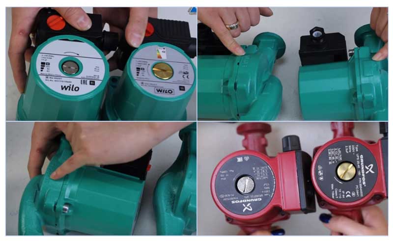
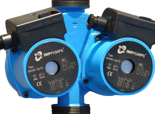
Rice. 8 The difference between a fake (right) and an original (left)
What else to pay attention to
When buying popular Grundfos and Wilo models, there is a high probability of a fake, so you should know some differences between the originals and Chinese counterparts. For example, German Wilo can be distinguished from a Chinese fake by the following features:
- The original sample is slightly larger in overall dimensions, its top cover has a serial number stamped on it.
- The embossed arrow of the direction of fluid movement in the original is placed on the inlet pipe.
- Air vent valve for fake yellow brass look (same color in analogues under Grundfos)
- The Chinese counterpart has a bright shiny sticker on the reverse side indicating energy saving classes.

Rice. 9 Criteria for selecting a circulation pump for heating
How to choose and buy a circulation pump
Circulation pumps face somewhat specific tasks, different from water, borehole, drainage, etc. If the latter are designed to move liquid with a specific spout point, then circulation and recirculation pumps simply “drive” the liquid in a circle.
I would like to approach the selection somewhat non-trivially and offer several options. So to speak, from simple to complex - start with the recommendations of manufacturers and the last to describe how to calculate a circulation pump for heating using formulas.
Choose a circulation pump
This easy way to choose a circulation pump for heating was recommended by one of the sales managers of WILO pumps.
It is assumed that the heat loss of the room per 1 sq. m. will be 100 watts. Formula for calculating the flow:
Total heat loss at home (kW) x 0.044 \u003d circulation pump consumption (m3/hour)
For example, if the area of a private house is 800 sq. m. the required flow will be:
(800 x 100) / 1000 \u003d 80 kW - heat loss at home
80 x 0.044 \u003d 3.52 cubic meters / hour - the required flow rate of the circulation pump at a room temperature of 20 degrees. WITH.
From the WILO range, TOP-RL 25/7.5, STAR-RS 25/7, STAR-RS 25/8 pumps are suitable for such requirements.
Regarding pressure. If the system is designed in accordance with modern requirements (plastic pipes, a closed heating system) and there are no non-standard solutions, such as a high number of storeys or a long length of heating pipelines, then the pressure of the above pumps should be enough "to the head".
Again, such a selection of a circulation pump is approximate, although in most cases it will satisfy the required parameters.
Select a circulation pump according to the formulas.
If there is a desire before buying a circulation pump to understand the required parameters and select it according to the formulas, then the following information will come in handy.
determine the required pump pressure
H=(R x L x k) / 100, where
H is the required pump head, m
L is the length of the pipeline between the most remote points "there" and "back". In other words, this is the length of the largest "ring" from the circulation pump in the heating system. (m)
An example of calculating a circulation pump using formulas
There is a three-storey house measuring 12m x 15m. Floor height 3 m. The house is heated by radiators ( ∆ T=20°C) with thermostatic heads. Let's calculate:
required heat output
N (ot. pl) \u003d 0.1 (kW / sq.m.) x 12 (m) x 15 (m) x 3 floors \u003d 54 kW
calculate the flow rate of the circulation pump
Q \u003d (0.86 x 54) / 20 \u003d 2.33 cubic meters / hour
calculate the pump head
The manufacturer of plastic pipes, TECE, recommends the use of pipes with a diameter at which the fluid flow rate is 0.55-0.75 m / s, the resistivity of the pipe wall is 100-250 Pa / m. In our case, a pipe with a diameter of 40mm (11/4″) can be used for the heating system. At a flow rate of 2.319 m3/hour, the coolant flow rate will be 0.75 m/s, the specific resistance of one meter of the pipe wall is 181 Pa/m (0.02 m of water column).
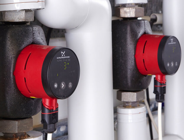
WILO YONOS PICO 25/1-8
GRUNDFOS UPS 25-70
Almost all manufacturers, including such "grands" as WILO and GRUNDFOS, place on their websites special programs for selecting a circulation pump. For the aforementioned companies, these are WILO SELECT and GRUNDFOS WebCam.
The programs are very convenient and easy to use.
Particular attention should be paid to the correct input of values, which often causes difficulties for untrained users.
Buy circulation pump
When buying a circulation pump, special attention should be paid to the seller. Currently, a lot of counterfeit products are “walking” on the Ukrainian market
How to explain that the retail price of a circulation pump on the market can be 3-4 times less than that of a representative of the manufacturer's company?
According to analysts, the circulation pump in the domestic sector is the leader in energy consumption. In recent years, companies have been offering very interesting new products - energy-saving circulation pumps with automatic power control. From the household series, WILO has YONOS PICO, GRUNDFOS has ALFA2. Such pumps consume electricity by several orders of magnitude less and significantly save the owners' money costs.
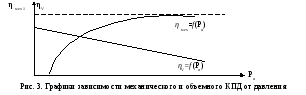
Checking the selected motor a. Checking the rudder time
For selected
pump look at the dependence graphs
mechanical and volumetric efficiency from
pressure created by the pump (see fig.
3).
4.1. Finding the moments
occurring on the motor shaft
at different rudder angles:
 ,
,
where: Mα
- moment on the motor shaft
(N m);
Qmouth
- installed performance
pump;
Pα
- oil pressure generated by the pump
(Pa);
Ptr
– losses friction pressure oils in
pipeline (3.4÷4.0) 105
Pa;
nn
- the number of revolutions of the pump (rpm);
ηr
is the hydraulic efficiency associated with
fluid friction in working cavities
pump (for rotary pumps ≈ 1);
ηfur
is the mechanical efficiency taking into account losses
friction (in seals, bearings and
other rubbing parts of pumps (see
graph in fig. 3).
Calculation data
put in table 4.
4.2. Finding speeds
motor rotation for received
moment values (according to the constructed
mechanical characteristic of the selected
electric motor - see item 3.6). Data
calculations are entered in table 5.
Table 5
|
α° |
n, |
ηr |
Qα, |
|
5 |
|||
|
10 |
|||
|
15 |
|||
|
20 |
|||
|
25 |
|||
|
30 |
|||
|
35 |
4.3. We find
actual performance
pump at received speeds
electric motor
 ,
,
where: Qα
- actual performance
pump (m3/s);
Qmouth
- installed performance
pump (m3/s);
n
– actual rotation speed
pump rotor (rpm);
nn
– rated rotor speed
pump;
ηv
is the volumetric efficiency taking into account the inverse
bypassing the pumped liquid (see
graph 4.)
Calculation data
put it in table 5. We build a graph Qα=f(α)
- see fig. 4.
Rice. 4. Graph
Qα=f(α)
4.4. Received
we divide the graph into 4 zones and determine
operating time of the electric drive in each
of them. The calculation is summarized in table 6.
Table 6
|
Zone |
Boundary |
Hi |
Vi |
Qcf. |
ti |
|
I |
|||||
|
II |
|||||
|
III |
|||||
|
IV |
4.4.1. We find
distance traveled by rolling pins
within the zone
 ,
,
where: Hi
- the distance traveled by the rolling pins in
within the zone (m);
Ro
- the distance between the axes of the baller and
rolling pins (m).
4.4.2. Finding the volume
oil pumped within the zone
 ,
,
where: Vi
– volume of pumped oil within
zones (m3);
mcyl
- the number of pairs of cylinders;
D
– plunger (rolling pin) diameter, m.
4.4.3. We find
rudder shift duration
within the zone
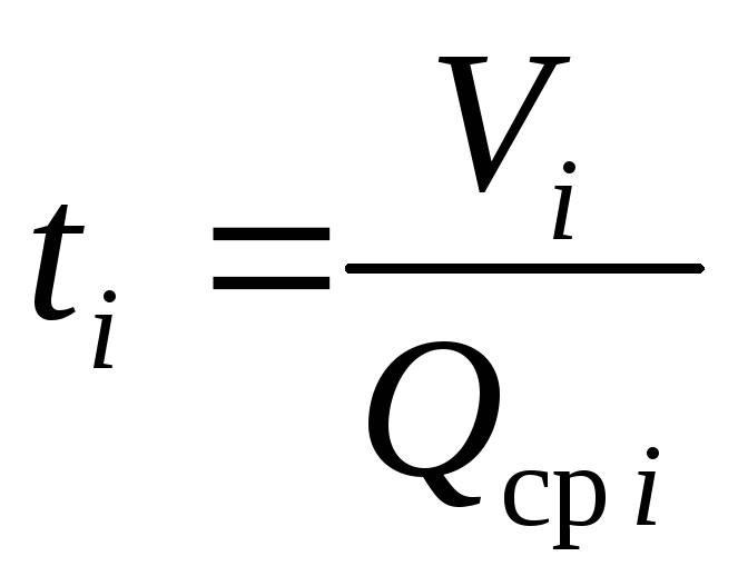 ,
,
where: ti
- average transfer time
steering within the zone (sec);
QWed
i
– average performance within
zones (m3/s)
- we take from the schedule p. 4.4. or we count
from table 5).
4.4.4. We define
operating time of the drive
shifting the rudder from side to side
tlane=
t1+
t2+
t3+
t4+
to,
where: tlane
- time to shift the rudder from side to side
(sec);
t1÷
t4
- the duration of the transfer in
each zone (sec);
to
is the time for the system to be ready for action (sec).
4.5. Compare t
shifting with T (rudder shifting time
from side to side at the request of RRR), sec.
tlane
≤
T
(30 sec)
12 Piston pump test
Pump test
produced in order to determine costs
power in individual parts of the pump.
When tested
remove the indicator diagram,
suction pressure gauge readings
and pressure gauge on the discharge, flow meter
and by electrical appliances is fixed
power consumed by the motor.
Most Interest
represents the indicator chart,
by which faults can be detected,
occurring in the hydraulic part
pump.
To merge charts
you can use mechanical
pressure indicator.
Drawing
5.26
Figure 5.26
schematic diagram presented
mechanical indicator installed
on the pump cylinder. The indicator consists
from drum 1, which is put on
paper, and hydraulic cylinder 2 attached
to the pump cylinder 4 through the tap 3. When
opening the tap pressure from the cavity
pump cylinder is transferred to the hydraulic cylinder
indicator, causing the piston to move
the last one. Indicator piston on its
the stock has a calibration for a certain
pressure spring 5 with lever, at the end
which the pencil is attached 6. Drum
rod 7 is connected to one of the parts
reciprocating pump
(stem 8), resulting in a reciprocating
drum movement corresponding to
piston stroke.
On the
lines are drawn on the paper of the drum,
equal or proportional to stroke length
piston at atmospheric pressure P
with previously opened З΄ and closed tap
Z and pressure lines for two piston strokes
RV
and RH
with tap 3 open and tap closed
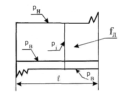
Z΄. The indicator obtained in this way
the diagram looks like (figure 5.27),
where p, p, p i
— suction, discharge and
indicator; fD
is the area of the diagram;
l—
chart length, equal or proportional
piston stroke length S.
Drawing
5.27
To
determine the mean pressure
according to the diagram, you need to know the constant
indicator springs - chart scale
by
height t (mm=1kgf/cm2).
 .
.
On the indicator
test chart
pump at the beginning of suction and discharge,
fixed etc. repeated fluctuations
valves, which is caused by a change in their
hydraulic resistance at
lifting from the saddle and subsequent free
movement; at significant pressures
pressure rise and fall lines
strictly vertical due to compressibility
fluid and blisters
gas.
By the type of indicator
charts can be set different
pump malfunctions. On the image
5.28 shows diagrams when the pump is running
with various faults: 1 - pump
sucks in air along with liquid
which compresses along the line “a”
at the beginning of the injection process; 2 - in
the cylinder has an air bag,
which shrinks along the line - “a”
at the beginning of the injection process and expands
along the line "in" at the beginning of the suction process;
3 - passes the suction valve; 4 -
skips the discharge valve; 5 -
insufficient (missing) volume
air cushion of pneumatic compensators.

Figure 5.28
Feeding performance of pumping equipment
This is one of the main factors to consider when choosing a device. Feed - the amount of coolant pumped per unit of time (m3 / h). The higher the flow, the greater the volume of fluid that the pump can pump. This indicator reflects the volume of the coolant that transfers heat from the boiler to the radiators. If the flow is low, the radiators will not heat up well. If the performance is excessive, the cost of heating the house will increase significantly.
The calculation of the power of the circulation pump equipment for the heating system can be made using the following formula: Qpu=Qn/1.163xDt [m3/h]
 At the same time, Qpu is the supply of the unit at the calculated point (measured in m3 / h), Qn is the amount of heat consumed in the area that is heated (kW), Dt is the temperature difference recorded on the direct and return pipelines (for standard systems this is 10- 20°C), 1.163 is an indicator of the specific heat capacity of water (if another coolant is used, the formula must be corrected).
How to determine the required pressure of the circulation pump
The head of centrifugal pumps is most often expressed in meters. The value of the pressure allows you to determine what hydraulic resistance it is able to overcome. In a closed heating system, the pressure does not depend on its height, but is determined by hydraulic resistances. To determine the required pressure, it is necessary to make a hydraulic calculation of the system. In private houses, when using standard pipelines, as a rule, a pump developing a pressure of up to 6 meters is sufficient.
You should not be afraid that the selected pump is able to develop more pressure than you need, because the developed pressure is determined by the resistance of the system, and not by the number indicated in the passport. If the maximum head of the pump is not enough to pump liquid through the entire system, there will be no liquid circulation, so you should choose a pump with a headroom .