What threatens to exceed the permitted power
At the moment, when the maximum load is exceeded, the electric company enters the mode of consumption limitation. The reason for this is a violation of the obligations prescribed in the energy supply agreement. As a rule, the limitation of consumption is a power outage. The algorithm for sending such a notification is shown in the figure.
 Consumer Notification Example
After 10 days, after sending the notice, the company performs a power outage. To avoid this, the consumer must eliminate the violation within ten days, and then contact the service provider to draw up an appropriate act. Electricity supply will be resumed after the electric company pays a penalty fee in accordance with the contract.
More serious consequences may arise if, in addition to violating the amount of allocated energy, an accusation of uncontrolled consumption of electricity is brought. The basis for this will be the removal of seals from the introductory machine. You can get more detailed information about the consequences of uncontrolled electricity consumption, electricity metering rules, etc. on our website.
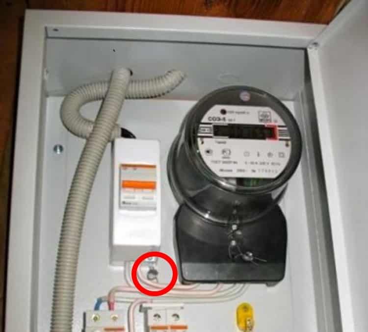 Seal on the introductory machine (marked in red)
Estimated power for industrial facilities
The design capacity of an industrial enterprise depends on:
- product type;
- technologies used;
- expected maximum load during the year;
- product type;
- type of equipment and degree of its adaptation to technology.
There are many calculation methods, all of them must have common properties:
- ease of calculation;
- universality in determining loads for different levels of energy consumption and distribution;
- accuracy of results;
- ease of determining the indicators on which the method is based.
The main indicators are calculated using the same formulas, but with different correction factors.
For three-phase electric motors, the installed power is:
Р \u003d Рн / (η x cos φ), where:
- Rn - nominal power indicator from the data sheet;
- η is the efficiency of the electric motor;
- cos φ - power factor.
An increase in the allocated power, according to the technical conditions, must be agreed with the power supply organization. For this purpose, recalculations are carried out for incoming cables and protection devices based on the new installed capacity. But the decision to allocate depends on the availability of free capacity.
What it is
During the capital construction of the times of the USSR, for example, in Khrushchev, i.e. in most of the residential premises operated to this day, even at the design stage, the allocated power was at the rate of 1.5 kW per 1 apartment. Later, the established norm of electricity increased to 3 kW, since it became necessary to increase it due to the increased "voracity" of consumers. Practice shows that plugs of 10-16 Amperes were usually installed in electrical panels and meters, so that the maximum current consumed by the apartment was limited to a total power of 3 kW for apartments with a gas stove. For apartments where an electric stove is installed, 7 kW is allocated. In new buildings, the allocated power can reach up to 15 kW. Such a spread is due to the fact that during the construction of old houses (60s, 70s) there were simply no such powerful consumers and as many household appliances as now.
Dedicated power is the maximum amount of electricity consumed at one time.
In addition, in order to enter the established limit, sometimes you need to enter not 1 phase, as often happens, but as many as 3 phases. This is necessary to connect modern household appliances, such as powerful electric boilers and electric stoves. This is especially true in commercial premises and industries of any scale, where a lot of electricity is needed (up to 30 kW and above).
Example
. For heating a country house not equipped with gas equipment, solid fuel and electric boilers are installed, the latter are safer and more convenient. For heating a house with an area of 100 sq.m. you need a boiler with a capacity of about 7-10 kW, the electric stove consumes another 3-5 kW. In total, it is necessary to increase the established limit of electricity to a minimum of 15 kW and input electricity in three phases.
To find out the allocated power for a private house or apartment, you need to contact the operating organization (in Moscow and the region, this is OJSC Mosenergosbyt). The certificate contains information about the allocated and average power consumption of electricity. It will be needed if you draw up documents for an increase, this will be discussed in more detail below.
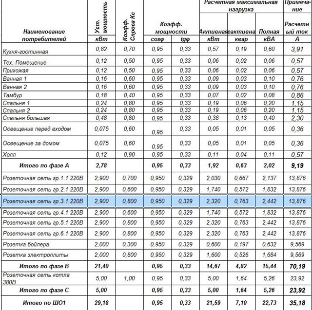
Estimated capacity of residential buildings
The installed power in a residential building is determined on the basis of the sum of the consumer rated powers of all electrical appliances and installations, and the calculated one, taking into account the expected coefficient of simultaneity of their inclusion.
Each subscriber has an act of delimitation, in which the installed capacity and the calculated one are recorded. For houses and apartments, these values \u200b\u200bare different. Three phases are usually supplied to houses and some apartments, which makes it possible to increase the consumed (calculated) indicator. Single-phase input significantly limits consumption. The load is controlled by protective equipment detuned from the maximum possible currents.
- If there is no power plant in the house or apartment, the calculated energy is determined by the formula:
P1 \u003d Rmax + M x Rchel, where:
- Pmax - the power of the largest receiver installed in the apartment,
- M is the number of inhabitants,
- Rchel - estimated power per person (for example, 1 kW);
Important!
This formula does not take into account the heating of residential premises.
- The design power of the power supply cable of an apartment building is made taking into account the number of apartments:
P \u003d P1 x n x k + Ra + Pl, where:
- n - number of apartments,
- k is the simultaneity coefficient (it ranges from 0.6 to 0.8),
- Pa - installed capacity of administrative power receivers,
- RL - elevators.
If there is no data, then Pa is taken equal to 0.5 kW, Pl = 20 kW.
- With electric heating, Ro = P + K1 x ΣRkv, where:
- P - rated power without electric heating,
- K1 - the coefficient of simultaneity of the heat load in n apartments,
- Rkv - heating energy in one apartment, kW.
Important!
Accurate determination of the design power required for space heating requires detailed calculations, which are carried out together with builders and building designers. In residential buildings with predominant heating elements cos φ = 1
- The calculated power indicator for a group of buildings is found by the empirical formula:
Pz = 0.95 x k x ΣP, where P is the energy for one building.
Calculation of the required power
This calculation will be needed to understand whether the amount of allocated electrical power for an apartment or house will be sufficient. To do this, you will need to calculate the maximum load by summing up the relevant parameters of all electrical installations of the consumer. Moreover, it is necessary to take into account all household electrical appliances that can be turned on at the same time.
As a rule, all the necessary information is indicated on a sticker affixed to the body of the equipment, or is given in the documentation. In the event that the sticker has become illegible, and the technical passport has been lost, you can use the table, which shows the typical active power of household equipment.
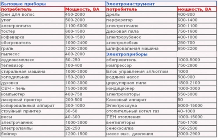 Table of estimated power consumption of various household appliances
After calculating the total consumption, do not rush to consider the work completed, you need to add a reserve, taking into account the possible increase in load over time. As a rule, the size of the reserve is set at 20-30% of the calculated parameters.
By adding these two values, we get a result that can be compared with the allowed power.If it turns out to be less than the calculated loads, it makes sense to think about applying for an additional 1 kW or 3 kW. Details on the connection of additional kilowatts will be discussed below.
Calculation of the maximum input power
Under the electrical load is understood the magnitude of the electric current flowing in the network when the power receiver or a group of power receivers is turned on.
According to electrical loads, conductors are selected (design, cross section) at all stages of generation, conversion, transmission and use by the consumer of electrical energy and its distribution. There are 3 methods for determining the electrical loads of objects:
1 Method for constructing a daily schedule of electrical loads;
2 The method of ordered diagrams or the method of the effective number of power receivers;
3 Analytical method
To calculate the load at the entrance to the building of the dairy unit, the method of constructing a daily schedule of electrical loads is used. Since at the facility it is possible to establish a cycle of technological equipment that is clear in time.
To build a load schedule, an auxiliary table No. 7 is compiled.
Table No. 7. - Auxiliary table for plotting loads.
|
Technological operation |
power, kWt |
The duration of the operation |
|||||||||||||||||||||
|
1 |
2 |
3 |
4 |
5 |
6 |
7 |
8 |
9 |
10 |
11 |
12 |
13 |
14 |
15 |
16 |
17 |
18 |
19 |
20 |
21 |
22 |
23 |
24 |
|
1 Milk pump |
2,2 |
||||||||||||||||||||||
|
2 Vacuum - pump |
8 |
||||||||||||||||||||||
|
3 Cooler |
18,74 |
||||||||||||||||||||||
|
4 Separator |
2,2 |
||||||||||||||||||||||
|
5 Heater |
12 |
||||||||||||||||||||||
|
6 Lighting |
1,74 |
A daily load schedule is drawn up (Figure 1).
Figure 1- Graph of electrical loads.
The graph shows that the maximum active power:
The installed power is determined by summing up all the loads available at the facility:
, (32)
where is the power of the i-th load, kW.
Power consumption per day is determined through the geometric area of the graph:
(33)
Average power consumption per day:
(34)
The average value of the power factor of the loads involved in the formation of the maximum loads:
(35)
The total power at the input is determined:
(36)
Input current at the moment of maximum load:
(37)
Based on the operating current, we determine the cross section of the input cable, based on the condition.
Iadditional ? Ip, (38)
Iadd = 65A? Ip = 52.65A.
We accept for installation the cable at the input AVBbShv 5 * 25.
Document overview
The procedure for the formation of a consolidated forecast balance of production and supply of electricity (capacity) within the framework of the Unified Energy System of Russia by regions was approved anew.
The tasks of forming a balance are to satisfy the demand for electricity and capacity, minimize the costs of their production and supply, ensure reliable energy supply, as well as balance the total cost of electricity and capacity supplied to the wholesale market at regulated prices (tariffs) and sold under regulated sales contracts. (deliveries) in price and non-price zones.
Balance is needed to achieve 3 goals. The first is the calculation of regulated prices (tariffs) for electricity and capacity subject to state regulation, as well as regulated prices (tariffs) for services provided in the wholesale and retail markets. The second is the conclusion by participants of the wholesale market of contracts, on the basis of which the purchase and sale of electricity and (or) capacity is carried out on such a market. The third is the conclusion by producers (suppliers) of contracts for the sale (supply) of electricity and capacity with a supplier of last resort in the regions united in non-price zones. We are talking about producers (suppliers) who are subject to the requirement of the legislation to sell the generated electricity (capacity) only on the wholesale market and who, before obtaining the status of a wholesale market entity, participate in purchase and sale relations on the retail market.
Also, the Procedure for determining the ratio of the total annual forecast volume of electricity consumption by the population and equated categories of consumers to the volume of electricity corresponding to the annual average value of the forecast volume of power determined in relation to these categories of consumers was approved.
The ratio is set to determine the planned volumes of consumption by the population for the next regulated period based on the results of control measurements. They are carried out by last resort suppliers, energy supply and sales organizations that supply electricity (capacity) to the population and categories of consumers equated to it in the year preceding the next regulated period.
The order to approve the previous procedure for the formation of the consolidated forecast balance sheet was declared invalid.
To view the current text of the document and obtain complete information about the entry into force, changes and the procedure for applying the document, use the search in the Internet version of the GARANT system:
Determination of the maximum capacities of consumers
We determine the load power of the substation
Sps= •Udn•(2•IeA•0.65•IeV)•0.83•KM ;kVA (2.1)
where, Udn- rated rectified voltage on the substation buses, kV,
Udn = 10kV;
IeA and IeV- effective currents of the substation, A;
TOM - coefficient taking into account the influence of intra-daily uneven movement, KM=1,45.
Sps= 10•(2•470+0.65•540)•0.83•1.45 = 15537.18 kVA
The maximum active power of consumers is determined by the formula
Pmax=Py•Kc, kW (2.2)
where, Py— installed capacity of electricity consumers, kW;
TOWith - demand coefficient, taking into account the mode of operation, loading and efficiency of additional equipment.
Consumer #1
Pmax1=Py1• TOc1 = 1400• 0.55 = 770 kW
Consumer #2
Pmax2 = Py2•TOc2= 1300 • 0.5 = 650 kW
Consumer #3
Rmax3 = Pbonds•TOcz = 1600 • 0.51 = 816 kW
Consumer #4
Rmax4 = Py4 •TOC4 = 1500 • 0.52 = 780 kW
We determine the reactive power of consumers
Q=Pmax•tgc kvar (2.3)
where tgц is determined by the known value cosц.
Pmax - active power of the consumer.
Consumer #1
Q1=Pmax1•tgC 1 \u003d 770 • 0.48 \u003d 369.6 kvar
Consumer #2
Q2=Pmax2•tgc2 = 650 • 0.62 = 403 kvar
Consumer #3
Q3 = Pmax3•tgc3= 816• 0.54 = 440.64 kvar
Consumer #4
Q4= Pmax4•tgC 4= 780 • 0.57 = 444.6 kvar
Determine the active total load
- ?Rmax = Pmax1 + Pmax2 + Pmax3 + Pmax4,+ Pmax5, kW (2.4)
- ?Pmax= 770 + 650 + 816 + 780 = 3016 kW
We determine the total reactive power of consumers
- ?Qmax = Q1 +Q2 +Q3 +Q4 +Q5, kvar (2.5)
- ?Qmax = 369.6 + 403 + 440.64 + 444.6 = 1657.84 kvar
Based on the maximum powers obtained and the given typical load curves, we calculate the active powers of each consumer for each hour of the day using the formula
kW, (2.6)
where pn - the number of percentages from the typical schedule for the n -th hour;
100 is a conversion factor from percent to relative units.
The calculation data of the active load by hours of the day for each consumer are summarized in Table 2.1
Table 2.1 Calculation of the active load of consumers
|
Clock |
Active load, kW |
Total |
|||
|
Consumer1 |
Consumer2 |
Consumer3 |
Consumer4 |
||
|
1 |
2 |
3 |
4 |
5 |
6 |
|
|
|
|
|
|
Based on the data in Table 2.1, we build a graph of the total load of consumers in Fig. 2.1.
What is the allocated power capacity
If we explain the meaning of this term in simple terms, then the allocated (or allowed) power is the maximum allowable load on the consumer's network. It is established in accordance with current regulations and is indicated in the power supply contract.
Those who want to understand this issue in detail should have an idea of the connected, installed, one-time and permitted power. Let's briefly define each of them:
- Connected, this term means the total installed capacity of all electrical receivers powered from the consumer's network.
- Installed - the rated active power specified in the technical documentation for electrical equipment, that is, the one at which consumer devices will operate in normal mode.
- One-time - the calculated value of the power consumption of the equipment of the electrical installation for a certain time.
- Dedicated (permitted) - the maximum one-time power that the consumer can connect to the grid of the power supply company. This parameter is indicated in the technical specifications for the connection of energy receiving facilities and in the contract between the consumer and the organization supplying electricity.
Installed capacity for power plants
For power plants, the installed power is calculated by summing the power ratings of the individual generators and associated motors. These values are almost always identical. In cases of discrepancy, the calculation is carried out at a lower power.
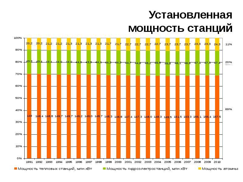
As a result, at expensive stations with great fuel economy, the cost of electricity is extremely dependent on the mode of consumption. Therefore, for large stations, it is advantageous to use the installed capacity for a maximum of hours per year, and for small gas turbines with high fuel consumption, it is more expedient to switch on during peak hours of load, when the total operating time on an annualized basis is small.
How to find out how much power is allocated
Those who do not know the amount of permitted power for a house or apartment can use the following methods to obtain information:
- Get a certificate from the power supply company. It should be borne in mind that such a service is considered paid, for example, in Mosenergosbyt, you will have to pay from 1.3 to 3.1 thousand rubles for it, depending on the category of a residential facility.
- Search for the required parameter in the power supply contract or technical specification.
- Get information empirically by looking at the parameters of the input protective device. The fact is that in most cases, in addition to its direct functions, it plays the role of a power limiter. To set its maximum value, it is enough to know the operating current of the machine.
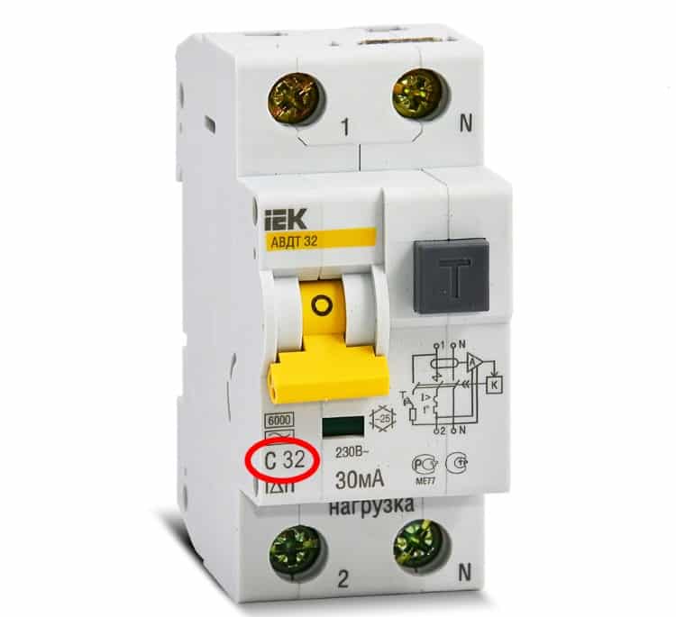 Operating current parameters (marked in red)
The figure shows a diffuser with a working current of 32 A (Inom). Therefore, the maximum allowable load power can be calculated by the formula: PMax = UxInom x 0.8; where U is the rated voltage of the network. Therefore, 230 x 32 x 0.8 ≈ 5.5 kW.
Of all the options presented, the first is the most reliable, especially since a certificate will still be needed if it is planned to increase the allocated capacity (it is included in the package of necessary documents).
A calculation based on the operating current of the introductory machine should not be trusted too much. Some models of modern electronic meters have a built-in load relay. In such cases, the rated current of the machine may be overestimated.
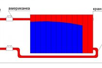
Clock for calculating the actual power value in the retail market
How to measure power consumption and check the meter How to measure power consumption and check the meter Knowing the power is required in many cases. For example: To calculate the required sections of the electrical cable. To determine the consumption of electricity consumed power. Let's dwell on the power consumption in more detail. Now there are many household appliances. Approximate operating time in hours and monthly energy consumption are indicated. Of course, the data are averaged, you can make a similar table for your technique. Calculate with new data. How can you measure power in everyday life? The most common way is with an electricity meter.
Conditions for transferring maximum power from an energy source to a receiver
Overhead line > AC circuits. Theory.
Conditions for transferring maximum power from an energy source to a receiver
Imagine an energy source with EMF E and internal resistance equivalent circuit (Fig. 3.22). Let us find out what the resistance Z \u003d r + jx of the receiver should be in order for the active power transmitted to it to be maximum. Receiver power
Obviously, for any r, the power reaches its maximum value at . In this case
Taking the derivative with respect to r from the resulting expression and equating it to zero, we find that P has the largest value at . Thus, the receiver receives the greatest active power from the source if its complex resistance is conjugated with the complex internal resistance of the source:
Under this condition
and efficiency
In electric power plants, the maximum power transmission mode is unprofitable due to significant energy losses.In various kinds of automation, electronics and communication devices, the signal powers are very small, so it is often necessary to specially create conditions for transmitting the maximum possible power to the receiver. The reduction in efficiency often does not matter, since the transmitted energy is small. The matching of the resistances of the receiver and the power source in accordance with (3.50) can also be obtained by adding elements with reactances to the circuit (see example 4.6). Sometimes the resistance of the receiver can not be changed arbitrarily, but only with the preservation of the ratio between active and reactive resistances, i.e. at . The analysis, which is not given here, shows that in this case the power P is maximum if the total impedances of the receiver and source () are equal to each other, while
Matching the impedances of the receiver and the power supply can be achieved by turning on the receiver through a transformer. In the general case of a receiver - a branched passive circuit Z - is its input impedance.
See more section on websor
- alternating currents
- The concept of alternators
- Sinusoidal current
- Operating current, emf and voltage
- Depiction of sinusoidal functions of time by vectors and complex numbers
- Addition of sinusoidal functions of time
- Electrical circuit and its diagram
- Current and voltage in series connection of resistive, inductive and capacitive elements
- resistance
- Voltage and current phase difference
- Voltage and currents with parallel connection of resistive, inductive and capacitive elements
- Conductivity
- Passive bipolar
- Power
- Powers of resistive, inductive and capacitive elements
- Power balance
- Power signs and direction of energy transfer
- Determining the parameters of a passive two-terminal network using an ammeter, voltmeter and wattmeter
- Conditions for transferring maximum power from an energy source to a receiver
- Understanding the Skin Effect and the Proximity Effect
- Parameters and equivalent circuits of capacitors
- Parameters and equivalent circuits of inductors and resistors
Estimated capacity of public buildings
- In general, for public buildings the following formula applies:
P \u003d Rgr x k x a, where:
- Рgr - installed power of a group of receivers in kW,
- k is the simultaneity factor for this group,
- a is the rated power utilization factor for a given group of receivers.
Both coefficients are in special tables.
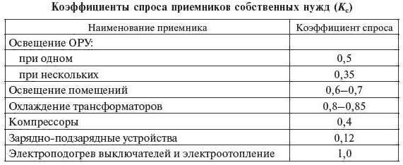
- Taking into account the electricity demand factor, another expression is used:
P = Kc x Rgr, where Kc is the demand coefficient (determined according to the table).
The value of Kc for non-residential facilities ranges from 0.2-0.4 to 1.
In the demand factor method, the calculated load does not depend only on the number of installed receivers. This is due to different demand factors. For large objects with a lot of different equipment, smaller values of Kc should be taken.
In non-industrial buildings: offices, schools, hospitals, theaters, hotels, etc., where lighting receivers and heating devices dominate, it is assumed that cos φ = 1.
The design capacity of the public utility building (boiler rooms, pumping stations) should be determined on the basis of the data from the catalog of manufacturers of electrical devices planned for installation, in accordance with the following formulas:
- reactive power of one receiver:
Q1 = tg φ x P1.
- for a group:
Q \u003d Kc x Qgr, where:
- for Qgr, all calculated values of individual receivers are added,
- Кс is the demand coefficient.
- active power indicator for the group:
P \u003d Kc x Rgr.
- general power:
S \u003d √ (P² + Q²).
Important!
Based on the given power values, tg φ for the group is calculated: tg φ = Q/P. If its value is greater than that specified in the technical conditions for connection, a decision is made on reactive power compensation

For a transformer substation from which residential and utility buildings will be powered, the calculated power is determined by:
S \u003d √ (P² + Rz² + Ros²) + (Q² + Qz² + Qos²), where:
- P and Q - indicators for public utilities buildings;
- Rz and Qz - for residential buildings;
- Ros and Qos - for street lighting installations.