Types of designs of heat pumps
 The type of HP is usually denoted by a phrase indicating the source medium and the heat carrier of the heating system.
There are the following varieties:
- TN "air - air";
- TN "air - water";
- TN "soil - water";
- TN "water - water".
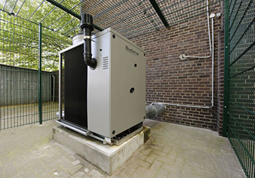
The very first option is a conventional split system operating in heating mode. The evaporator is mounted on the street, and a block with a condenser is installed inside the house. The latter is blown by a fan, due to which warm air mass is supplied to the room.
If such a system is equipped with a special heat exchanger with nozzles, an air-to-water heat pump will be obtained. It is connected to the water heating system.
An air-to-air or air-to-water HP evaporator can be placed not on the street, but in the exhaust ventilation duct (it must be forced). In this case, the efficiency of HP will be increased several times.
Heat pumps of the "water - water" and "soil - water" types use the so-called external heat exchanger or, as it is also called, a collector to extract heat.
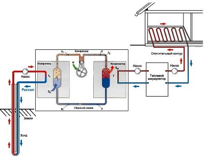
Schematic diagram of the heat pump
This is a long looped pipe, usually plastic, through which a liquid medium circulates, washing the evaporator. Both types of HP are the same device: in one case, the collector is immersed to the bottom of a surface reservoir, and in the second, to the ground. The condenser of such a HP is located in a heat exchanger connected to a water heating system.
Connecting a HP according to the "water - water" scheme is much less laborious than "soil - water", since there is no need for earthworks. At the bottom of the reservoir, the pipe is laid in the form of a spiral. Of course, only such a body of water is suitable for this scheme, which does not freeze to the bottom in winter.
It is time to study foreign experience in detail
Almost everyone already knows about heat pumps capable of extracting ambient heat for heating buildings, and if until recently a potential customer, as a rule, asked a bewildered question “how is this possible?”, Now the question “how is it right” is increasingly heard. do?".
It is not easy to answer this question.
In search of an answer to the numerous questions that inevitably arise when trying to design heating systems with heat pumps, it is advisable to turn to the experience of specialists from those countries where heat pumps on ground heat exchangers have been used for a long time.
A visit * to the American exhibition AHR EXPO-2008, which was undertaken mainly to obtain information on the methods of engineering calculations of ground heat exchangers, did not bring direct results in this direction, but a book was sold at the ASHRAE exhibition stand, some of the provisions of which served as the basis for this publications.
It should be said right away that the transfer of American methods to domestic soil is not an easy task. Americans do not do things the way they do in Europe. Only they measure time in the same units as we do. All other units of measurement are purely American, or rather, British. The Americans were especially unlucky with the heat flux, which can be measured both in British thermal units per unit of time, and in tons of cooling, which were probably invented in America.
The main problem, however, was not the technical inconvenience of recalculating the units of measurement accepted in the United States, to which one can get used to over time, but the absence in the mentioned book of a clear methodological basis for constructing a calculation algorithm. Routine and well-known calculation methods are given too much space there, while some important provisions remain completely undisclosed.
In particular, such physically related input data for the calculation of vertical ground heat exchangers, such as the temperature of the liquid circulating in the heat exchanger and the heat pump conversion coefficient, cannot be set arbitrarily, and before proceeding with calculations related to unsteady heat transfer in the ground, it is necessary to determine the dependencies connecting these options.
The criterion for the efficiency of a heat pump is the conversion factor α, the value of which is determined by the ratio of its thermal power to the power of the compressor electric drive. This value is a function of the boiling temperatures in the evaporator tu and condensation tk, and in relation to heat pumps "water-water" we can talk about the temperature of the liquid at the outlet of the evaporator t2I and at the output of the capacitor t2K:
? = ?(t2I,t2K). (1)
An analysis of the catalog characteristics of serial refrigeration machines and water-to-water heat pumps made it possible to display this function in the form of a diagram (Fig. 1).
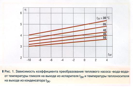
Using the diagram, it is easy to determine the parameters of the heat pump at the very initial stages of design. It is obvious, for example, that if the heating system connected to the heat pump is designed to supply a heating medium with a flow temperature of 50°C, then the maximum possible conversion factor of the heat pump will be about 3.5. At the same time, the temperature of the glycol at the outlet of the evaporator should not be lower than +3°C, which means that an expensive ground heat exchanger will be required.
At the same time, if the house is heated by underfloor heating, a coolant with a temperature of 35°C will enter the heating system from the heat pump condenser. In this case, the heat pump can work more efficiently, for example, with a conversion factor of 4.3, if the temperature of the cooled glycol in the evaporator is about -2°C.
Using Excel spreadsheets, you can express the function (1) as an equation:
? = 0.1729 • (41.5 + t2I – 0.015t2I • t2K – 0.437 • t2K (2)
If, with the desired conversion factor and a given value of the coolant temperature in the heating system powered by a heat pump, it is necessary to determine the temperature of the liquid cooled in the evaporator, then equation (2) can be represented as:
(3)
To select the temperature of the heat carrier in the heating system for given values of the heat pump conversion coefficient and the temperature of the liquid at the outlet of the evaporator, you can use the formula:
(4)
In formulas (2)…(4) temperatures are expressed in degrees Celsius.
Having determined these dependencies, we can now proceed directly to the American experience.
Methodology for calculating heat pumps
Of course, the process of selecting and calculating a heat pump is a technically very complex operation and depends on the individual characteristics of the object, but approximately it can be reduced to the following steps:
Heat losses through the building envelope (walls, ceilings, windows, doors) are determined. This can be done using the following ratio:
Qok \u003d S * ( tin - tout) * (1 + Σ β ) * n / Rt (W) where
tout - outside air temperature (°С);
tin – internal air temperature (°С);
S is the total area of all enclosing structures (m2);
n is a coefficient indicating the influence of the environment on the characteristics of the object. For premises in direct contact with the external environment through ceilings n=1; for objects with attic floors n=0.9; if the object is located above the basement n = 0.75;
β is the coefficient of additional heat loss, which depends on the type of building and its geographical location; β can vary from 0.05 to 0.27;
Rt - thermal resistance, is determined by the following expression:
Rt = 1/ αinternal + Σ ( δi /λi ) + 1/αbunk (m2*°С / W), where:
δi / λі is the calculated indicator of thermal conductivity of materials used in construction.
αbunk- coefficient of thermal dissipation of the outer surfaces of enclosing structures (W / m2 * ° C);
αinternal- coefficient of thermal absorption of the internal surfaces of enclosing structures (W / m2 * ° C);
- The total heat loss of the structure is calculated according to the formula:
Qt.pot \u003d Qok + Qi - Qbp, where:
Qi - energy costs for heating the air entering the room through natural leaks;
Qbp - heat release due to the functioning of household appliances and human activities.
2. Based on the data obtained, the annual consumption of thermal energy is calculated for each individual object:
Qyear = 24*0.63*Qt. sweat.*(( d*( tin — tout.av.)/ ( tin — tout.)) (kWh per year) where:
tvn - recommended air temperature inside the room;
tout - outside air temperature;
tout.average - the arithmetic mean of the outdoor air temperature for the entire heating season;
d is the number of days of the heating period.
3. For a complete analysis, it will also be necessary to calculate the level of thermal power required to heat the water:
Qhv \u003d V * 17 (kW / h per year.) where:
V is the volume of daily heating of water up to 50 °C.
Then the total consumption of thermal energy is determined by the formula:
Q \u003d Qgw + Qyear (kW / h per year.)
Taking into account the obtained data, it will not be difficult to choose the most suitable heat pump for heating and hot water supply. Moreover, the calculated power is determined as. Qtn=1.1*Q, where:
Qtn=1.1*Q, where:
1.1 - correction factor indicating the possibility of increasing the load on the heat pump during the occurrence of critical temperatures.
Having performed the calculation of heat pumps, you can choose the most suitable heat pump that can provide the required microclimate parameters in rooms with any technical characteristics. And given the possibility of integrating this system with a heated floor air conditioning unit, it can be noted not only its functionality, but also its high aesthetic value.
Read more:
How to correctly calculate the number and depth of wells for HP can be found in the following video:
If you liked the material, I will be grateful if you recommend it to friends or leave a useful comment.
Types of heat pumps
Heat pumps are divided into three main types according to the source of low-grade energy:
- Air.
- Priming.
- Water - The source can be groundwater and water bodies on the surface.
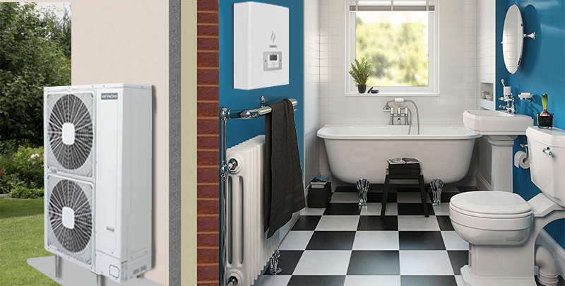
For water heating systems, which are more common, the following types of heat pumps are used:
 "Air-to-water" - an air type heat pump that heats the building by drawing air from outside through an external unit. It works on the principle of an air conditioner, but in reverse, converting the energy of the air into heat. Such a heat pump does not require large installation costs, it does not need to allocate a piece of land for it and, moreover, drill a well. However, the efficiency of operation at low temperatures (-25ºС) decreases and an additional source of thermal energy is required.
The "ground-water" device refers to geothermal and produces heat from the ground using a collector laid to a depth below the freezing of the soil. There is also a dependence on the area of the site and the landscape, if the collector is located horizontally. For a vertical arrangement, a well will need to be drilled.
 "Water-water" is installed where there is a reservoir or groundwater nearby. In the first case, the collector is laid on the bottom of the reservoir, in the second, a well is drilled or several, if the site area allows. Sometimes the depth of groundwater is too great, so the cost of installing such a heat pump can be very high.
Each type of heat pump has its advantages and disadvantages, if the building is far from a body of water or the groundwater is too deep, then water-to-water will not work."Air-water" will be relevant only in relatively warm regions, where the air temperature during the cold season does not fall below -25º C.
Method for calculating the power of a heat pump
In addition to determining the optimal energy source, it will be necessary to calculate the power of the heat pump required for heating. It depends on the amount of heat loss of the building. Let's calculate the power of a heat pump for heating a house using a specific example.
To do this, we use the formula Q=k*V*∆T, where
- Q is heat loss (kcal/hour). 1 kWh = 860 kcal/h;
- V is the volume of the house in m3 (we multiply the area by the height of the ceilings);
- ∆Т is the ratio of the minimum temperatures outside and inside the premises during the coldest period of the year, °С. From the internal tº we subtract the external one;
- k is the generalized heat transfer coefficient of the building. For a brick building with two layers of masonry k=1; for a well-insulated building k=0.6.
Thus, the calculation of the power of a heat pump for heating a brick house of 100 sq.m and a ceiling height of 2.5 m, with a difference in ttº from -30º outside to +20º inside, will be as follows:
Q \u003d (100x2.5) x (20- (-30)) x 1 \u003d 12500 kcal / hour
12500/860= 14.53 kW. That is, for a standard brick house with an area of 100 m2, you will need a 14-kilowatt device.
The consumer accepts the choice of the type and power of the heat pump based on a number of conditions:
- geographical features of the area (proximity of water bodies, the presence of groundwater, a free area for a collector);
- climate features (temperature);
- type and internal volume of the room;
- financial opportunities.
Considering all the above aspects, you will be able to make the best choice of equipment. For a more efficient and correct selection of a heat pump, it is better to contact specialists, they will be able to make more detailed calculations and provide the economic feasibility of installing the equipment.
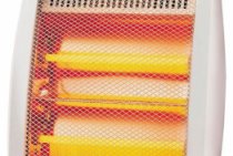
For a long time and very successfully, heat pumps have been used in household and industrial refrigerators and air conditioners.
Today, these devices began to be used to perform the function of the opposite nature - heating the home during the cold season.
Let's see how heat pumps are used for heating private houses and what you need to know in order to correctly calculate all its components.
Heat pump calculation example
We will select a heat pump for the heating system of a one-story house with a total area of 70 sq. m with a standard ceiling height (2.5 m), rational architecture and thermal insulation of enclosing structures that meet the requirements of modern building codes. For heating the 1st sq. m of such an object, according to generally accepted standards, has to spend 100 W of heat. Thus, for heating the whole house you will need:
Q \u003d 70 x 100 \u003d 7000 W \u003d 7 kW of thermal energy.
We choose a heat pump brand "TeploDarom" (model L-024-WLC) with a heat output of W = 7.7 kW. The compressor of the unit consumes N = 2.5 kW of electricity.
Collector calculation
The soil in the area allotted for the construction of the collector is clayey, the groundwater level is high (we take the calorific value p = 35 W/m).
Collector power is determined by the formula:
Qk \u003d W - N \u003d 7.7 - 2.5 \u003d 5.2 kW.
L = 5200 / 35 = 148.5 m (approx.).
Based on the fact that laying a circuit longer than 100 m is irrational due to excessively high hydraulic resistance, we assume the following: the heat pump collector will consist of two circuits - 100 m and 50 m long.
The area of the site that will need to be taken under the collector is determined by the formula:
S = L x A,
Where A is the step between adjacent sections of the contour. We accept: A = 0.8 m.
Then S = 150 x 0.8 = 120 sq. m.
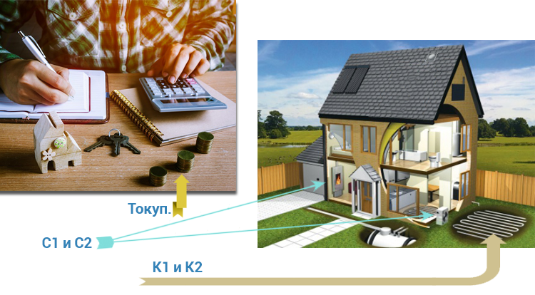
Payback of a heat pump
When it comes to how long a person will be able to return his money invested in something, it means how profitable the investment itself was. In the field of heating, everything is quite difficult, since we provide ourselves with comfort and warmth, and all systems are expensive, but in this case, you can look for an option that would return the money spent by reducing costs when using. And when you start looking for a suitable solution, you compare everything: a gas boiler, a heat pump or an electric boiler. We will analyze which system will pay off faster and more efficiently.
The concept of payback, in this case, the introduction of a heat pump to modernize the existing heat supply system, if simply, can be explained as follows:
There is one system - an individual gas boiler, which provides independent heating and hot water. There is a split-system air conditioner that provides cold to one room. Installed 3 split systems in different rooms.
And there is a more economical advanced technology - a heat pump that will heat / cool houses and heat water in the right quantities for a house or apartment. It is necessary to determine how much the total cost of equipment and initial costs has changed, as well as to assess how much the annual costs of operating the selected types of equipment have decreased. And to determine how many years more expensive equipment will pay off with the resulting savings. Ideally, several proposed design solutions are compared and the most cost-effective one is selected.
We will calculate and find out what is the payback period of a heat pump in Ukraine
Consider a specific example
- House on 2 floors, well insulated, with a total area of 150 sq. m.
- Heat / heating distribution system: circuit 1 - underfloor heating, circuit 2 - radiators (or fan coil units).
- A gas boiler for heating and hot water supply (DHW), for example, 24kW, double-circuit, is installed.
- Split air conditioning system for 3 rooms of the house.
Annual heating and water heating costs
| Max. heat output HP for heating, kW | 19993,59 |
| Max. power consumption HP when working for heating, kW | 7283,18 |
| Max. heating capacity of HP for hot water supply, kW | 2133,46 |
| Max. power consumption HP when working on hot water supply, kW | 866,12 |
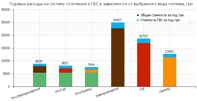
- The approximate cost of a boiler room with a 24 kW gas boiler (boiler, piping, wiring, tank, meter, installation) is about 1000 Euros. An air conditioning system (one split system) for such a house will cost about 800 euros. In total, with the arrangement of the boiler room, design work, connection to the gas pipeline network and installation work - 6100 euros.
- Approximate cost of a Mycond heat pump with additional fan coil system, installation work and electrical connection is 6650 euros.
- The growth of capital investments is: K2-K1 = 6650 - 6100 = 550 euros (or about 16500 UAH)
- The reduction in operating costs is: C1-C2 = 27252 - 7644 = 19608 UAH.
- Payback period Tokup. = 16500 / 19608 = 0.84 years!
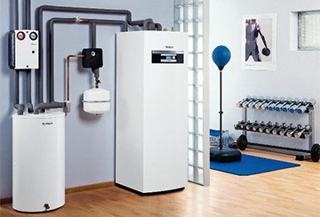
Ease of use of the heat pump
Heat pumps are the most versatile, multifunctional and energy efficient equipment for heating a house, apartment, office or commercial facility.
An intelligent control system with weekly or daily programming, automatic switching of seasonal settings, maintaining the temperature in the houses, economical modes, control of a slave boiler, boiler, circulation pumps, temperature control in two heating circuits, is the most advanced and advanced. Inverter control of the operation of the compressor, fan, pumps, allows maximum savings in energy consumption.
Heat pump operation during ground-water operation
Laying the collector in the ground can be done in three ways.
Horizontal option
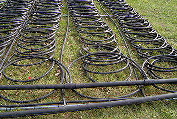 Pipes are laid in trenches "snake" to a depth exceeding the depth of soil freezing (on average - from 1 to 1.5 m).
Such a collector will require a plot of land of a sufficiently large area, but any homeowner can build it - no skills other than the ability to work with a shovel will be needed.
It should, however, be taken into account that the construction of a heat exchanger by hand is a rather laborious process.
Vertical option
Collector pipes in the form of loops, having the shape of the letter "U", are immersed in wells with a depth of 20 to 100 m. If necessary, several such wells can be built. After the pipes are installed, the wells are filled with cement mortar.
The advantage of a vertical collector is that a very small area is needed for its construction. However, there is no way to drill wells with a depth of more than 20 m on your own - you will have to hire a team of drillers.
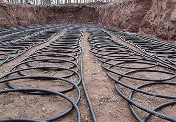
Combined variant
 This collector can be considered a variation of the horizontal one, but it will require much less space to build.
A round well is dug on the site with a depth of 2 m.
The heat exchanger pipes are laid in a spiral, so that the circuit is like a vertically mounted spring.
Upon completion of the installation work, the well falls asleep. As in the case of a horizontal heat exchanger, all the necessary amount of work can be done by hand.
The collector is filled with antifreeze - antifreeze or ethylene glycol solution. To ensure its circulation, a special pump crashes into the circuit. Having absorbed the heat of the soil, the antifreeze enters the evaporator, where heat exchange takes place between it and the refrigerant.
It should be taken into account that the unlimited extraction of heat from the ground, especially when the collector is located vertically, can lead to undesirable consequences for the geology and ecology of the site. Therefore, in the summer, it is highly desirable to operate the HP of the "soil - water" type in the reverse mode - air conditioning.
The gas heating system has a lot of advantages and one of the main ones is the low cost of gas. How to equip home heating with gas, you will be prompted by the heating scheme of a private house with a gas boiler. Consider the design of the heating system and the requirements for replacement.
Read about the features of choosing solar panels for home heating in this topic.
Calculation of the horizontal collector of a heat pump
The efficiency of a horizontal collector depends on the temperature of the medium in which it is immersed, its thermal conductivity, as well as the area of contact with the pipe surface. The calculation method is rather complicated, therefore, in most cases, averaged data are used.
 It is believed that each meter of the heat exchanger provides the HP with the following heat output:
- 10 W - when buried in dry sandy or rocky soil;
- 20 W - in dry clay soil;
- 25 W - in wet clay soil;
- 35 W - in very damp clay soil.
Thus, to calculate the length of the collector (L), the required thermal power (Q) should be divided by the calorific value of the soil (p):
L = Q / p.
The values given can only be considered valid if the following conditions are met:
- The land above the collector is not built up, shaded, or planted with trees or bushes.
- The distance between adjacent turns of the spiral or sections of the "snake" is at least 0.7 m.
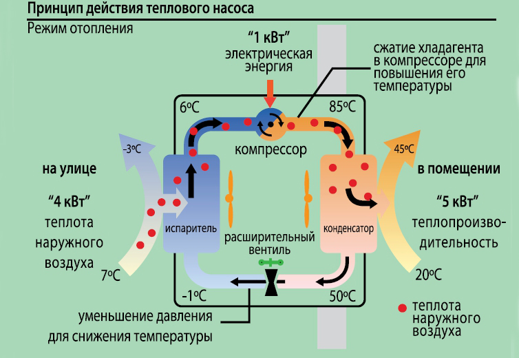
How heat pumps work
In any HP there is a working medium called a refrigerant. Usually freon acts in this capacity, less often - ammonia. The device itself consists of only three components:
The evaporator and condenser are two reservoirs that look like long curved tubes - coils. The condenser is connected at one end to the compressor outlet, and the evaporator to the inlet. The ends of the coils are joined and a pressure reducing valve is installed at the junction between them. The evaporator is in contact - directly or indirectly - with the source medium, while the condenser is in contact with the heating or DHW system.
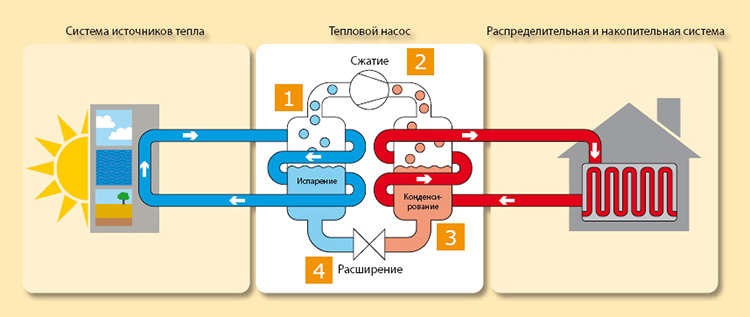
How a heat pump works
The operation of HP is based on the interdependence of volume, pressure and temperature of the gas. Here is what happens inside the aggregate:
- Ammonia, freon or other refrigerant, moving through the evaporator, heats up from the source medium, for example, to a temperature of +5 degrees.
- After passing the evaporator, the gas reaches the compressor, which pumps it into the condenser.
- The refrigerant pumped by the compressor is held in the condenser by a pressure reducing valve, so its pressure is higher here than in the evaporator. As you know, with increasing pressure, the temperature of any gas increases.This is exactly what happens to the refrigerant - it heats up to 60 - 70 degrees. Since the condenser is washed by the coolant circulating in the heating system, the latter is also heated.
- Through the pressure reducing valve, the refrigerant is discharged in small portions into the evaporator, where its pressure drops again. The gas expands and cools, and since part of the internal energy was lost by it as a result of heat transfer at the previous stage, its temperature drops below the initial +5 degrees. Following the evaporator, it heats up again, then it is pumped into the condenser by the compressor - and so on in a circle. Scientifically, this process is called the Carnot cycle.
But HP still remains very profitable: for each kWh of electricity spent, it is possible to obtain from 3 to 5 kWh of heat.
Influence of initial data on the calculation result
Let us now use the mathematical model built in the course of calculations in order to trace the influence of various initial data on the final result of the calculation. It should be noted that the calculations performed on Excel allow such an analysis to be carried out very quickly.
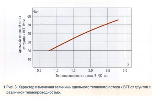
To begin with, let's see how its thermal conductivity affects the magnitude of the heat flux to the WGT from the ground.
Our calculation example was performed for soil with thermal conductivity ? \u003d 2.076 W / (K • m), and the specific heat flux was qyd = 41.4 W. On fig. 3 shows the function qyd = ?(?) with other calculation conditions unchanged.
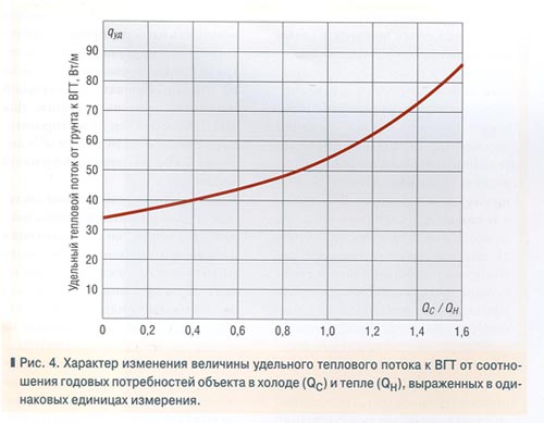
It is known that when VGT is used in summer in the mode of removing heat from the refrigerating machines of the air conditioning system, the efficiency of ground heat exchangers operating in winter together with a heat pump increases. The curve in fig. Figure 4 shows the nature of the dependence of the specific heat flux from the ground to the VGT in winter on the ratio of the building's annual need for cold to its annual need for heat for heating.
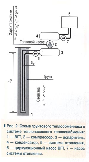
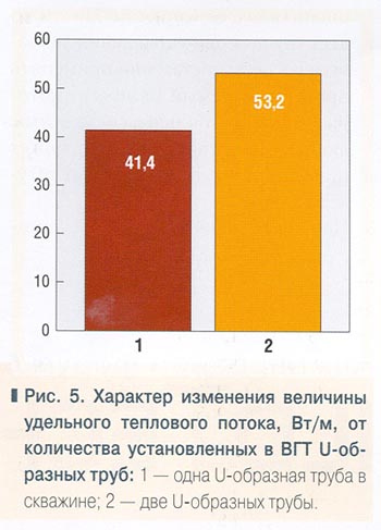
In European practice, in the construction of ground source heat pumps, VGTs with two U-shaped polyethylene pipes installed in one well are usually used. The mathematical model makes it possible to evaluate the effectiveness of such a technical solution (Fig. 5). The values of the specific heat flux in the left and right columns of the diagram are calculated for the values of the equivalent diameter of the VGT, corresponding to the design of the heat exchanger with one and two U-tubes.
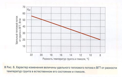
The temperature difference between the ground and the glycol cooled in the evaporator of the heat pump is decisive for the intensification of heat transfer in the ground. On fig. 6 shows the dependence of the specific heat flux on this temperature difference.
It should be especially noted that Figures 3…6 do not display the absolute values of the specific heat flux from the soil to the VGT, but the nature of the change in these values from one of the arguments, while many other arguments remain unchanged, or rather, as they were defined or given in our calculation example. Therefore, it is impossible to be guided by the diagrams shown in these figures to calculate the length of the VGT in specific projects.
It is recommended to determine the length of vertical ground heat exchangers using formula (6).