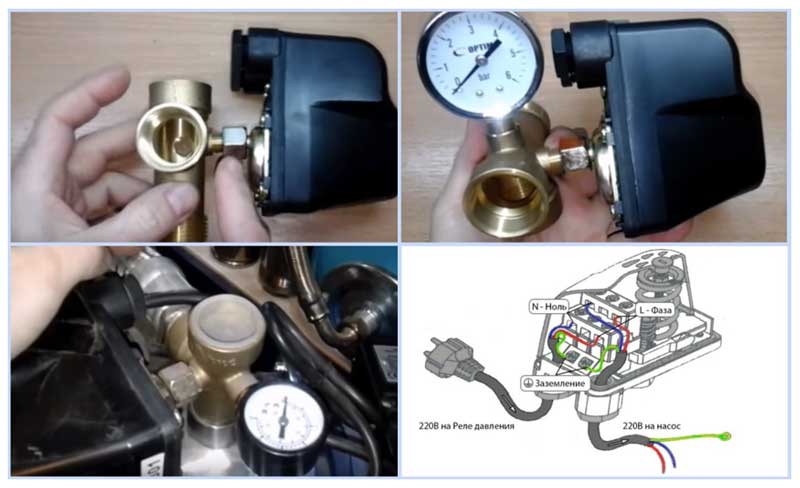
The device (RD, RM) is screwed into the adapter using a union nut (American threaded connection) - this allows you to leave the body in a stationary position when connected, without rotating it around its axis. In such a device, a rubber gasket under the union nut ensures the tightness of the connection, but there are other types of devices with a fixed fitting that has an external or internal thread without gaskets. In this case, flax fiber or a special thread for waterproofing fittings of sanitary fittings is used for sealing; the option of installing a sealant from the popular FUM tape is not very effective - it is often cut through with sharp threads.
Connecting the device to an AC voltage of 220 volts does not cause any particular difficulties - two ends of one of the electric pump power wires are connected to terminals M1 and M2 and fixed with screws, if there is a ground wire in the power supply, it is connected to the block located in the lower part of the case, with a pressure plate and a screw.
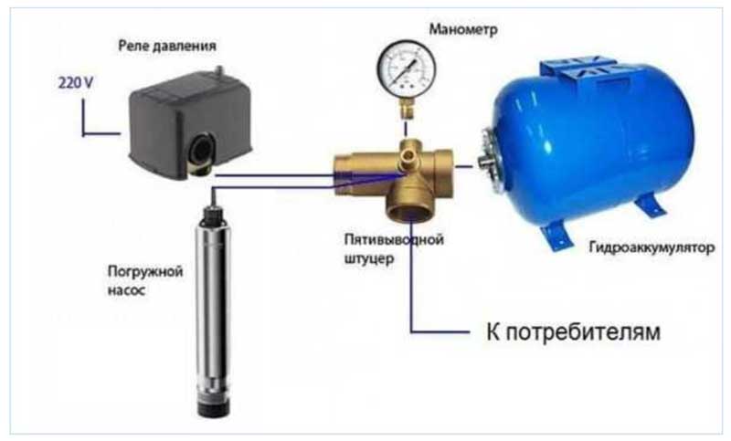
Rice. 8 Relay in the automation of a submersible pump - connection diagram through a five-way fitting
There are three types of pressure transducers that measure absolute, differential, and gauge pressure.
Absolute pressure, such as barometric pressure, is measured with an absolute pressure sensor. Pressure is measured relative to vacuum.
Differential pressure, such as differential pressure in differential flow meters, is measured with a differential pressure transmitter (fig. 1).
Rice. 1. Diagram of a differential pressure sensor.
Gauge pressure is measured relative to some reference value. An example is the measurement of blood pressure, which is carried out relative to atmospheric pressure. Gauge pressure is essentially a variation of differential pressure. Measure the pressure, excess relative to atmospheric, with a manometer.
In pressure sensors, capacitive-type secondary transducers are also used. In such devices, the entire surface of the membrane acts as a capacitor plate. A fixed metal base is used as one plate of the capacitor, the other plate is a flexible round-shaped membrane fixed around the circumference. The membrane flexes under pressure. When the membrane is deformed, the average distance between the capacitor plates decreases, which leads to an increase in capacitance.
The use of MEMS technology makes it possible to obtain micromechanical and optical units of smaller sizes than is possible with traditional technologies. The advantage of MEMS is the electronic part, and electrical connections with sensors and mechanisms, made using integrated technology and having small dimensions. The high repeatability of sensitive elements, and their integrated fabrication together with the processing circuit, can significantly improve the accuracy of measurements. Thanks to the integrated technology, the reliability of MEMS is higher than the reliability of a similar system that is assembled from discrete components. Also, optical systems have greater reliability and durability, since they are located in a sealed case and are protected from environmental influences. The use of MEMS reduces the cost of both mechanical and electronic parts of the device, since the processing electronics and MEMS are integrated on a single substrate, which avoids additional connections and, in some cases, the use of matching circuits.
The pressure sensor is installed as a separate device in most automatic control systems, it is also part of the control units for pumping equipment of the 2nd and 3rd generations, in which all automation is located in one housing.
Rice. 5 Relay diagram on the example of model RD 2
The main sign of a sensor malfunction is the lack of information about the level of pressure in the wheel on the monitor. The reasons may be the used battery limit, a weak information signal, mechanical failure during installation. As a rule, it is required to replace the defective sensor with a new one. If the information signal from the sensor antenna is weak, it is recommended to determine the most effective location by turning. Replacing batteries is often a technically difficult operation, requires tire fitting with an internal location of the sensor and may not give the expected result.
VIDEO ipt>
The main malfunctions of sensors are:
possible etching of all external and internal brass-rubber sensors;
sticking of an external aluminum sensor with a brass valve;
false operation of the ABS system during a long turn.
In some TPMS systems, the disadvantages are:
low brightness and small display numbers;
displaying the indicators of only one tire on the screen with the need to call the data of other wheels on the screen by pressing a button;
interference from the radio, walkie-talkie when submitting information to the screen;
the need for tire fitting to replace the batteries of internal sensors;
risk of theft of external sensors;
lack of settings for pressure parameters;
the impossibility of turning off the sound signal;
discrepancy between the dimensions of the plug of the device and the car cigarette lighter;
the requirement for additional balancing when installing external sensors.
The tests carried out have shown the high quality of the following non-standard tire pressure monitoring systems,
with internal sensors:
CRX-1006 (high quality, reliable performance);
TPMS CRX-1001 (real-time information, large numbers, high battery capacity);
TPMS-201 (easy setting);
Parkmaster 4-03 (installation of the monitor module in the cigarette lighter, display brightness);
with external sensors:
CRX-1041 (quick set, wide pressure range);
CRX-1002 (corrosion and theft protection).
Tire pressure monitoring systems are becoming a prerequisite for improving the safety and durability of vehicles. Currently, in a number of countries, the production of machines with the installation of this option is legally determined.On the market, car enthusiasts can independently select and install tpms tire pressure sensors in accordance with their budgetary capabilities, levels of performance and control of the required parameters.
Design features
As mentioned above, there are both mechanical and electronic water pressure switches. For both, the main working organ is the membrane, which acts as one of the walls of their internal container, into which water enters. Deviating under the pressure of water, the membrane acts on the remaining elements of the sensor, as a result, the device is triggered.
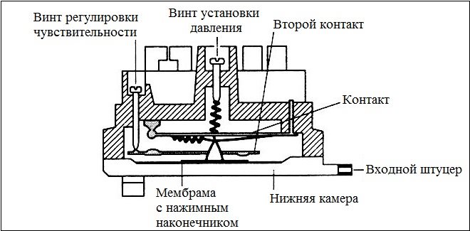
Membrane pressure sensor device
The elements affected by the deflecting membrane in mechanical sensors are contacts that, when closed or opened, turn on and off the pumping equipment. The electronic pressure sensor works on a slightly different principle. The deformation of the membrane in such a device is converted into a control electrical analog signal, which is then amplified, digitized and fed to the pipeline automatic control unit.
Mechanical pressure sensors, which are also called contact, are used more often than electronic ones. This is explained both by the simplicity of the design of such a device and its more affordable cost. In particular, mechanical water pressure sensors are regularly installed in domestic heating and water supply systems.
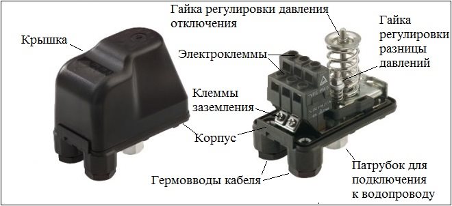
Household water pressure switch device
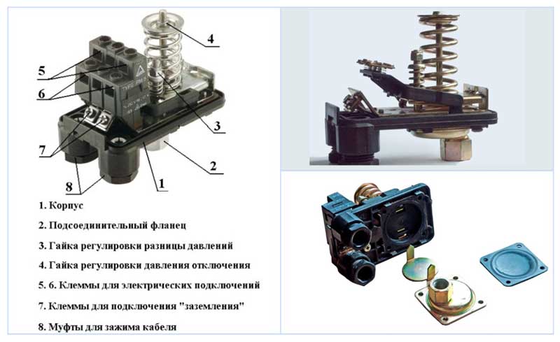
The design of the mechanical sensor is:
branch pipe, with the help of which the device is connected to the elements of the pipeline;
membrane;
contact Group;
two springs of different diameters, through which the maximum and minimum pressure levels are set at which the device should operate.
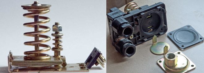
Disassembled pressure sensor
A larger diameter spring, installed in mechanical type sensors, determines the level of water pressure in the pipeline at which the device will operate and turn off the supply pump. The second spring is responsible for the lower limit of the sensor's response, or to be more precise, the range of values beyond which the sensor will turn on and start the pump that supplies water to the pipeline.
The design of mechanical sensors provides for the ability to adjust the degree of compression of both springs. When a spring of a larger diameter is compressed, the value of the water pressure at which the device will operate increases. If you compress a spring of smaller diameter more, then the pressure difference between the response levels will increase.
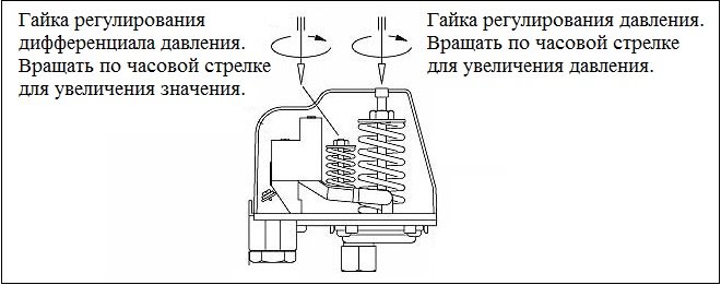
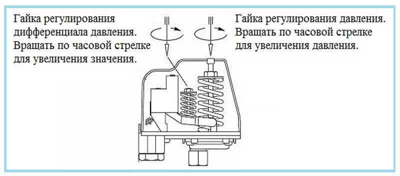
The principle of adjusting the mechanical pressure sensor
Installation and setup
Standard pressure control systems installed at factories do not require additional actions. It is only necessary to periodically check the health of the system nodes.
An additional system in the form of sensors with color information of the pressure level is installed on the nipples instead of protective caps.
A freelance system in the form of external sensors with information transmission requires the receiver to be installed in the console and connected to one of the cabin devices with a screen.
A system with internal sensors requires the installation of sensors inside the tires instead of valves, pre-setting the unit for the minimum and maximum pressure levels, and alarm settings.
Registration, activation, of electronic sensors is carried out in a circle - first the front left wheel, then the front right, rear right and rear left wheels.
VIDEO Regular and self-installed systems provide high-quality pressure control in accordance with the technical level of the product.
Checking the tire pressure sensor
The readings of the sensors are checked by control measurements of pressure with conventional pressure gauges. Their accuracy is 0.1 bar, which is quite enough. A deeper check of the sensors and the entire system is carried out by special devices.If the low pressure alarm stays on, it is recommended that you do the following:
visually carefully inspect the wheel for defects;
pump up to the required parameters in a tire shop;
drive for some time at a speed of no more than 80 km / h.
The error signal should stop and the system will work normally.
Reset tire pressure sensor
If the error persists on the monitor, it is recommended to completely deflate the wheel and re-inflate it, as well as reboot the pressure control system software device (on-board computer, special monitor unit, etc.).
VIDEO Disabling the tire pressure sensor
In the event of a malfunction of one of the sensors, before replacing it, it is allowed to turn it off. Disabling the pressure sensor is carried out in accordance with the instructions of the system. In this case, the system continues to control the remaining 3 wheels. If there is no button to turn off the sound signal, it is allowed to disconnect the faulty sensor from the unit.
An example of the operation of a frequency converter on a demonstration stand
All over the world, frequency converters have been used to control pumps for a long time. Unfortunately, in Russia this technique has not yet taken root. Let's tell you what is the beauty of these small, uncomplicated boxes, and what a huge plus they give the consumer when they are used in a private water supply system.
What is a frequency converter? As a rule, owners of houses and cottages use submersible borehole pumps in their water supply systems. These pumps are controlled by pressure switches and hydraulic accumulators of various capacities.
The pressure switch has two thresholds: upper and lower. With such a device of the water supply system, at the moment when the pump is turned on, the pressure drops very much and this is uncomfortable for the consumer. He experiences discomfort because the pressure changes. This is especially true when taking a shower. Cottage owners are well aware of this, as they have already encountered this problem. For those who are just about to equip their water supply system, this information will help in presenting the expected effect.
How to improve comfort so that the pressure in the system is constant? There is a solution to this problem. This is the application of a frequency converter. Many companies supply Italtecnica chastotniki. This concern produces frequency converters with single-phase pumps of the SIRIO ENTRY series. These frequency converters can control single-phase pumps up to 1.5 kilowatts.
What models of sensors are
There are mechanical and electronic modifications of sensors, for domestic water supply using submersible electric pumps and pumping stations of the budget and medium price categories, mechanical models of this device are mainly used. They are characterized by high reliability, simple design, ease of installation and adjustment.
The use of expensive electronic pressure sensors in conventional water intake systems only for opening contacts does not make sense, the electronics are designed for smooth control of the operating modes of pumping equipment.
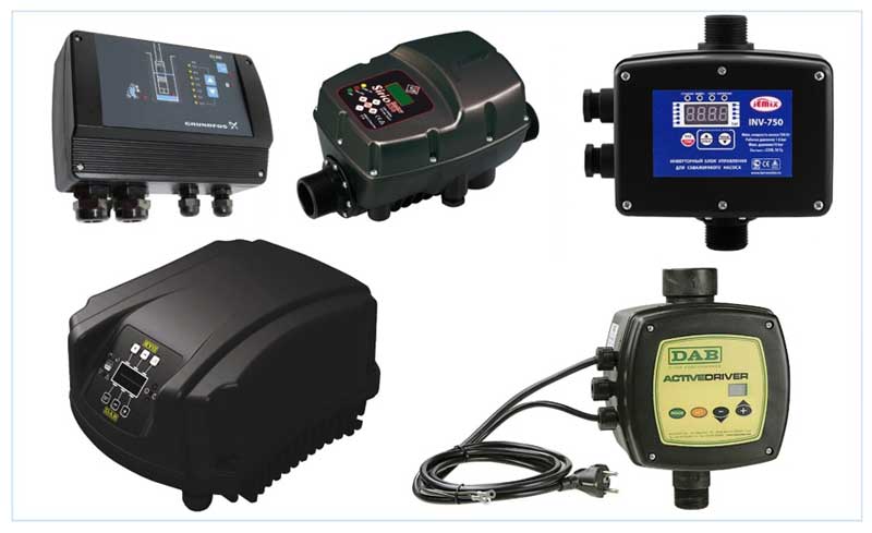
Rice. 6 Automatic control devices with built-in sensors
Electronic water sensors
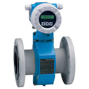
Electronic hydraulic pressure sensors are used in automatic control of pumping equipment of the 3rd generation with a frequency converter; they are part of electronic controllers consisting of one small-sized unit.
The electronic device replaces all discrete elements of the automation system - a dry-running and pressure switch, a pressure gauge, a large-volume hydraulic accumulator, provides smooth start of the electric motor and electronic control of the speed of rotation of the pump motor shaft.In this device, an analog signal is taken from the electronic sensor, the voltage value of which depends on the pressure, then it is converted in the electronic control circuit into a pulse-width modulated voltage supplied to the pump motor winding.
In everyday life, special frequency control units SU 301 from Grundfos, paired with submersible electric pumps of the SQ series, are widely known and used, other well-known models and manufacturers are Active Driver (DAB), Sirio Entry (Italtecnica).
Rice. 7 Connecting the sensor to the water supply and electrical network
Principle of operation
Consider a PM pressure sensor installed in an individual water supply system, it functions as follows:
The pressure created by the well or well pump contributes to filling the line with water, which presses on the rubber membrane located behind the pressure switch fitting.
Inside the device, a plate with pointed conical protrusions along the edges is placed on an elastic membrane; when the membrane moves under pressure deep into the device, the plate simultaneously shifts and its tips press on the plate that opens the electrical contacts inside the case.
Since one or two wires of the electric pump power cable are connected to the contacts, the circuit opens and the power supply to the electric motor stops, the device stops its work.
With domestic use of water, the pressure in the pipeline drops, the relay membrane returns to its original position, loosening the pressure on the plate, and the contacts inside the device close - the electric pump starts to function and pump water into the line.
Rice. 4 Disassembled water pressure sensor RM
Installation
Considering that most water flow sensors are structurally part of the devices, their installation is required only in case of replacement in case of failure. However, there are situations when the water flow sensor must be installed separately, for example, when it becomes necessary to increase the pressure of the water supply.
Indeed, situations often occur when there is insufficient pressure in the central water supply system, and in order to turn on the gas boiler in the hot water supply mode, it is necessary to create a good pressure. In this case, an additional circulation pump is installed, equipped with a water flow sensor.
In this case, the sensor is installed after the pump, so when the water begins to move, the sensor turns on the pump and the water pressure rises.
VIDEO Adjustment and tuning
In domestic use, the consumer often prefers inexpensive and reliable models of domestic production - sensors of the RD-5, RM-5 series, and their various modifications, in order for the selected device to work correctly, it must be properly configured for the line parameters. The factory settings for the on-off values of the relay and, accordingly, the thresholds for the operation of the pump of these devices are 1.4 - 2.8 bar.
Rice. 9 Specifications for popular types of relays
If the internal main line is long or the pipeline is located in a high-rise building, the upper and lower limits of the relay operation must be reconfigured. If it is necessary to carry out adjustment operations, the built-in pressure gauge serves as a control and measuring device, according to which readings are recorded, adjustment operations are carried out in the following sequence:
The electric pump is disconnected from the electrical network, the top cover of the device is removed to gain access to two adjusting spring-loaded screws, the largest spring is responsible for the upper threshold, and the small one can adjust the difference between the limits. By rotating the nut over a large spring, a change in the upper pressure threshold is achieved - by turning clockwise, the upper limit of operation is increased, by rotating in the opposite direction, when the spring is weakened, the limit is reduced.
When adjusting with a large spring, make several turns of the nut on the large screw in the right direction, after which the electric pump is turned on and the moment it is turned off is recorded on the pressure gauge.
If the readings do not correspond to the required ones, they drain the water from the internal water supply and wait for the electric pump to turn on again - when the minimum pressure threshold is reached, the relay starts.
The operation is periodically repeated until the cut-off pressure of the electric pump reaches the desired value according to the indications of the pressure gauge pointer.
After setting the upper threshold, they begin to regulate the minimum allowable lower limit, while it should be borne in mind that the difference between the boundary response levels should be at least 1.5 bar.
By turning the nut on the small screw in one direction or another, you can set the delta, after adjusting, water is drained from the filled line and, according to the pressure gauge, the moment when the relay turns on the pump is fixed. If the required lower limit is not reached, the adjustment and draining of the water is repeated several times until the required difference of at least 1.5 bar is reached.
It should be noted that the greater the difference between the thresholds, the less often the pump is turned on, and when the pump operates in this mode, the life of its and other automatic equipment increases.
Rice. 10 Setting and adjusting the water pressure sensor
VIDEO
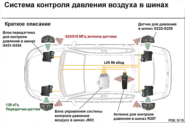
Sensor options
For security reasons, a decision was made to mandatory install standard systems in the US and EU countries, and also caused the production of systems for self-installation.
Sensors are mechanical and electronic, with internal and external installation, direct or indirect control.
Tire pressure sensor
Regular sensors are installed at the factory during the production of machines and are connected to a computer unit. Information about a specific pressure level is displayed either on the display or on the reverse mirror. In the event of a sensor failure, replacement is possible only with a similar model. High-precision indoor sensors are used.
It is also widely practiced in car factories to use ABS sensors to detect a decrease in pressure using programs by changing the speed of a flat wheel. This is much cheaper, but only the fact of insufficient pressure is determined, without fixing the actual level.
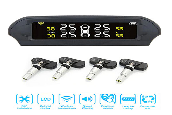
External tire pressure sensors
The production of systems using external and internal sensors for installation in machines has been established in the world.
The simplest are systems with sensors mounted on nipples. The pressure level can be reported to the driver in different ways:
the corresponding color of the sensor caps (green for pressures over 2 bar, yellow for 1 to 2 bar and red for less than 1 bar);
via the Bluetooth system to the salon or your Android or iOs mobile device;
on the supplied monitor.
The main disadvantage is the impossibility of obtaining information about the pressure during movement.
TPMS with internal sensors
Internal sensors, additionally purchased to install the control system, are similar to the sensors of regular systems. They are placed inside the wheel instead of valves. The absence of software requires either the purchase of an additional monitor or the use of a Bluetooth channel to transmit information to the salon or your mobile device. The system provides high data accuracy and allows additional adjustment of information signals. Installation of sensors and their maintenance requires tire fitting operations.
Installation Recommendations
When placing a pressure sensor in the line, the following recommendations must be observed:
For the device to work correctly, the temperature range in which it is operated must not exceed -4 - +40 C.
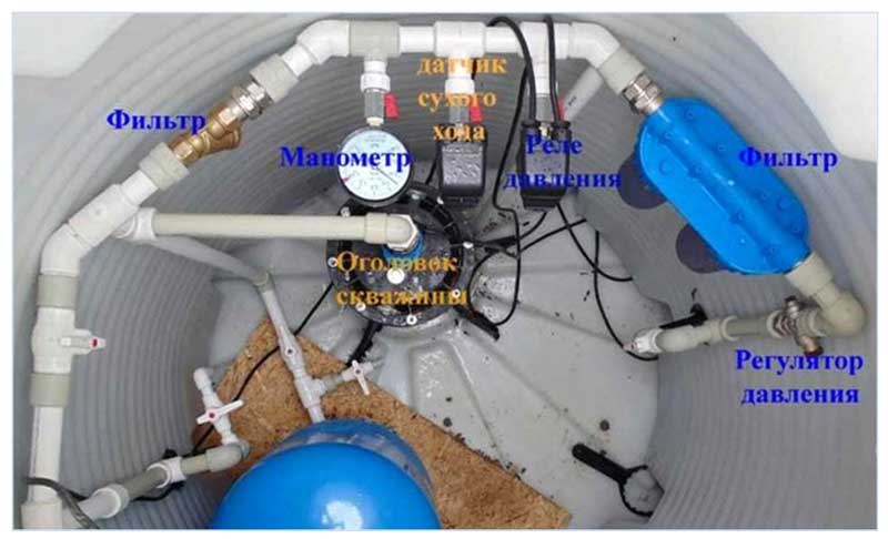
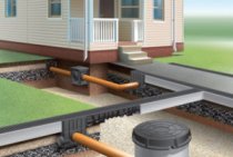
Automation is placed not only indoors at home, but also in a caisson well, after the pump, filters for fine and deep water purification should be installed in the line - this will prevent the fitting with a membrane from clogging with dirt, which can lead to incorrect operation of the device.
Many devices are designed to work only with cold water; during operation, its temperature should not exceed the permissible limits, for example, no more than +55 C. for RD models.
The power of the electric pump connected through the device must not exceed the values specified in the passport data - violation of this rule can lead to sticking of the contacts and failure of the relay.
Rice. 11 An example of the placement of a hydraulic switch with a deep-well electric pump
A pressure sensor or pressure switch is the main device for ensuring the automatic operation of water intake equipment; it is part of any electric pumping station or water supply system with a deep-well electric pump. Its installation and adjustment does not present any particular difficulties even for an unprepared homeowner, and compliance with the basic rules for placement and installation will ensure uninterrupted operation of the device for a decade.
VIDEO
Kinds
Today, two types of water flow sensors have found the greatest application - a Hall sensor and a reed relay.
The flow water sensor, based on the principle of operation of the Hall sensor (it is also called a flow meter), is a small turbine on which a magnet is mounted. When the turbine rotates, the magnet creates a magnetic field and, like a turbine in a hydroelectric power plant, it generates small electrical impulses that go to the boiler control board. The speed of rotation of the turbine depends on the speed of the water supply, the greater the flow, the clearer the pulses. Thus, thanks to the Hall sensor, it is possible not only to signal the flow of water, but also the speed of the water supply.
The reed water flow sensor is a sensor based on the principles of a magnet. Basically, this sensor looks like this - inside the chamber made of composite material there is a magnetic float, with an increase in water pressure, the float moves around the chamber and acts on the reed switch.
The reed switch, and this is nothing more than two magnetic plates in a chamber without air, opens under the influence of the magnetic field of the float, and the control board switches the boiler to hot water mode.
Reed water level sensor:
Water flow meter:
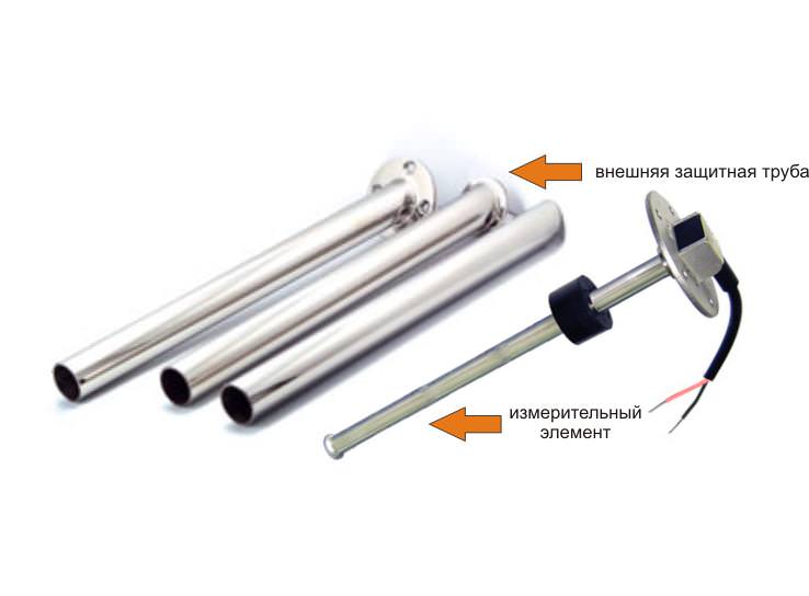
 Rice. 1 The principle of operation of the float level sensor (PDU)