The main reasons why the air compressor does not gain pressure are repair methods.
Depressurization of connecting elements and nodes.
When subjected to vibrations for a long time, seals, nuts and clamps may loosen, resulting in air leakage. First of all, the user needs to check the main threaded connections and nozzles. And also the places of connection of measuring devices (pressure gauge), valves and other modules. If a problem is found, you need to take a wrench of the appropriate size and tighten all nuts and couplings tightly. In some cases, the gaskets may need to be replaced.
If after the above procedures the problem is not resolved, the user should arm himself with a soapy solution and coat all connections with it. After starting the compressor, bubbles will form at the place of depressurization
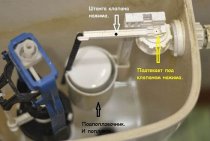
Particular attention should be paid to the condensate drain valve. As experience shows, most of these problems occur in this area.
Worn compression rings and valve plates.
Another answer to the question why the compressor is not gaining pressure.
To begin with, the master must check the suction by unscrewing the air filter, and the exhaust force at the outlet of the piston block.
During the operation of piston pneumatic stations, the main load falls on the sealing rings
Their replacement will not require large expenses, and the master will carry out the procedure quickly enough.
Also a common problem is a broken check valve. This is usually accompanied by compressor overheating. It must be disassembled and checked for faults or foreign elements.
Reduced motor power.
Often the efficiency of an electric motor is reduced due to internal contamination and soot. Sometimes this is due to the use of unsuitable technical fluids or poor quality oils. Also, users do not always regularly check the engine air filter, which clogs the piston group, rings and other elements of the mechanism. In this case, an increase in the consumption of lubricating fluids and clogging of the pneumatic flow with oil occurs. Over time, parts can begin to overheat and fail.
The electric motor must be inspected and serviced by an experienced technician. In some cases, it may be necessary to replace a large number of expensive parts.
A compressor is a device that compresses gas or air. The final pressure created at the outlet is higher than atmospheric and is called the discharge pressure, and the unit itself is called the supercharger. The principle of operation is simple: pistons or screws progressively drive the gas, thus compressing and reducing the volume.
The compressor is used in everyday life: , bicycles; when repairing an apartment, pneumatic grinders, hammer, drills.
Superchargers are used in industry: in air cooling systems; in construction; for transport on the railway - ensure the operation of the brake system. In the oil refining industry and metalworking, a centrifugal compressor is used - a unit with a radial design, the performance of which far exceeds that of other types of superchargers.
Wiring diagram
Pressure switches for compressors can be for different load connection schemes. For a single-phase engine, a 220 volt relay is used, with two groups of connections. If we have three phases, then install a device for 380 volts, which has three electronic contacts for all three phases.For a motor with three phases, you should not use a relay to the 220 volt compressor, because one phase will not be able to turn off the load.
flanges
Additional connection flanges may be included with the device. Usually equipped with no more than three flanges, with a hole size of 1/4 inch. Thanks to this, additional parts can be connected to the compressor, for example, a pressure gauge or a safety valve.
Pressure switch connection
Relay installation
Let us turn to such a question as connecting and adjusting the relay. How to connect the relay:
- We connect the device to the receiver through the main output.
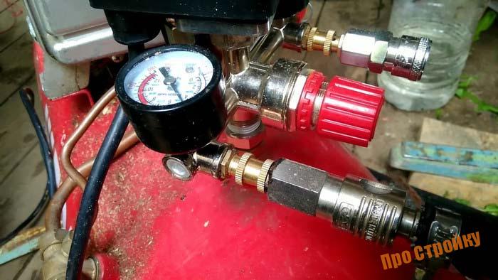
- If necessary, connect a pressure gauge if flanges are present.
- If necessary, we also connect an unloading and safety valve to the flanges.
- Channels that are not used must be closed with plugs.
- Connect the electric motor control circuit to the contacts of the pressure switch.
- The current consumed by the motor must not exceed the voltage of the pressure switch contacts. Motors with low power can be installed directly, and with high power they put the necessary magnetic starter.
- Adjust the parameters of the highest and lowest pressure in the system using the adjusting screws.
The compressor relay should be adjusted under pressure, but with the engine power off.
When replacing or connecting a relay, you should know the exact voltage in the network: 220 or 380 volts
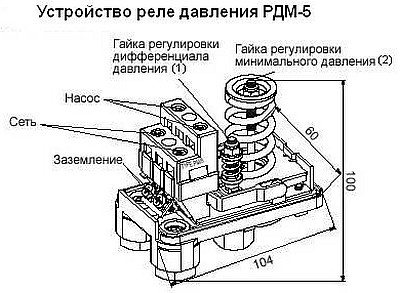
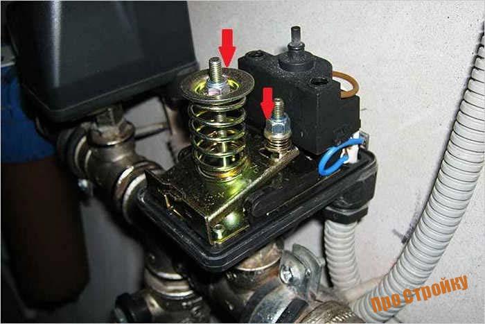
Relay adjustment
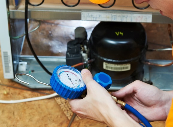
The pressure switch is usually sold already configured and adjusted by the manufacturer, and does not need additional adjustments. But sometimes it becomes necessary to change the factory settings. First you need to know the range of parameters of the compressor. Using a pressure gauge, determine the pressure at which the relay turns on or off the motor.
After determining the desired values, the compressor is disconnected from the network. Then remove the relay cover. Under it there are two bolts of slightly different sizes. The larger bolt adjusts the maximum pressure when the engine should be turned off. Usually it is denoted by the letter P and an arrow with a plus or minus. To increase the value of this parameter, the screw is turned towards the "plus", and to decrease - towards the "minus".

The smaller screw sets the pressure difference between on and off. It is indicated by the symbol "ΔΡ" and an arrow. Usually the difference is set at 1.5-2 bar. The higher this indicator, the less often the relay turns on the engine, but at the same time the pressure drop in the system will increase.
Operation and maintenance
First of all, it should be noted that even with timely maintenance, equipment, or some of its elements, wear out sooner or later.
Before starting the operation of the compressor, it is necessary to carefully read all the factory rules and recommendations, as well as regularly inspect the external structure. Any, even minor external damage can lead to premature failure of the equipment, as well as to the fact that the compressor stops pumping pressure.
It is highly desirable to entrust all technical operations to experienced professionals who use professional tools and diagnostic devices.
DIY pressure switch
If you have a working thermostat from an old refrigerator at home, as well as some work skills, then you can safely make a pressure switch for a compressor with your own hands. However, it is worth warning in advance that such a solution cannot differ in great practical possibilities, since the upper pressure with such an approach will be limited only by the strength of the rubber bellows.
Work order
After opening the cover, the location of the required group of contacts is found out, for this purpose the circuit is called.The first step is to refine the connection of the compressor with the thermal relay: the contact groups are connected to the terminals of the electric motor circuit, and the unloading valve is connected to the outlet pipe with a control pressure gauge. The adjusting screw is located under the thermostat cover.
When the compressor is started, the screw rotates smoothly, at the same time, you need to monitor the readings of the pressure gauge. It is worth taking care that the receiver is filled by 10-15 percent! To achieve the minimum pressure, it is necessary to smoothly move the stem of the face button. To this end, the cover is placed in its original place, after which the adjustment is performed almost blindly, since there is nowhere to install the second pressure gauge.
For safety reasons, it is not recommended to set the thermostat pressure beyond 1-6 atm! If devices with a stronger bellows are used, the maximum range can be raised to 8-10 atm, which is usually enough for most tasks.
The capillary tube is cut off only after you make sure that the relay is working. After the release of the refrigerant inside, the end of the tube is placed inside the unloading valve and soldered.
The next step is a homemade pressure switch for the compressor is connected to the control circuit. To do this, the relay is fixed to the control board with a nut. The locknut is screwed onto the threads on the stem, thanks to which the air pressure can be adjusted in the future.
Taking into account the fact that the contact group of the thermal relay from any refrigerator is designed to work with high currents, they can switch quite powerful circuits, for example, secondary circuits when working with a compressor engine
Compressor pressure regulation
As mentioned above, after creating a certain level of air compression in the receiver, the pressure switch turns off the engine of the unit. Conversely, when the pressure drops to the switch-on limit, the relay starts the engine again.
But often situations that arise make you change the factory settings of the pressure switch and adjust the pressure in the compressor at your discretion. Only the lower turn-on threshold will be changed, since after changing the upper turn-off threshold upwards, the air will be discharged by the safety valve.
The pressure in the compressor is adjusted as follows.
- Turn on the unit and record the pressure gauge reading at which the engine turns on and off.
- Be sure to disconnect the device from the mains and remove the cover from the pressure switch.
- After removing the cover, you will see 2 bolts with springs. The large bolt is often denoted by the letter "P" with the signs "-" and "+" and is responsible for the upper pressure, at which the device will be turned off. To increase the air compression level, turn the regulator towards the “+” sign, and to decrease it, towards the “-” sign. First, it is recommended to make half a turn of the screw in the desired direction, then turn on the compressor and check the degree of pressure increase or decrease using a pressure gauge. Fix at what indicators of the device the engine will turn off.
- With a small screw, you can adjust the difference between the on and off thresholds. As mentioned above, it is not recommended that this interval exceed 2 bars. The longer the interval, the less often the machine's engine will start. In addition, there will be a significant pressure drop in the system. Setting the difference between the on-off thresholds is done in the same way as setting the upper on-off threshold.
In addition, it is necessary to configure the reducer, if it is installed in the system. It is necessary to set the pressure reducer to a level that corresponds to the working pressure of the pneumatic tool or equipment connected to the system.
In most cases, inexpensive models of air compressors are not equipped with a pressure switch, since such products are mounted on the receiver. Based on this, many manufacturers think that visual control of pressure through a pressure gauge will be more than enough. However, with prolonged use of the device, if you do not want to bring the engine to overheating, it makes sense to install a pressure switch for the compressor! With this approach, the shutdown and start of the drive will be carried out automatically.
Purpose
The function of air compressors is to receive a stream of air with a certain pressure, it must be stable and uniform. It should also be possible to change the parameters of this jet. Each compressor has a reservoir (cylinder) for air. It must have the necessary pressure. When lowering it, you should turn on the motor to replenish the air supply. In case of excessive pressure, the air supply must be stopped so that the container does not burst. This process is controlled by a pressure switch.
With its proper functioning, the engine is preserved, it is protected from frequent switching on and off, the operation of the system is uniform and stable. The tank membrane is connected to the pressure switch. Moving, it can turn on and off the relay.
Principle of operation
Considering the pressure in the system, the relay serves to open and close the voltage circuit, starts the compressor in case of insufficient pressure and turns it off when the parameter rises to the set point. This is the principle of normally closed loop operation for motor control.
The reverse principle of operation is also found, when the relay turns off the electric motor at the minimum pressure in the circuit, and turns it on at the maximum. This is a normally open loop circuit.
The working system consists of springs of different stiffness levels that respond to pressure changes. During operation, the deformation forces of the springs and the pressure of compressed air are compared. When the pressure changes, the spring mechanism is activated, and the relay closes or opens the electrical circuit.
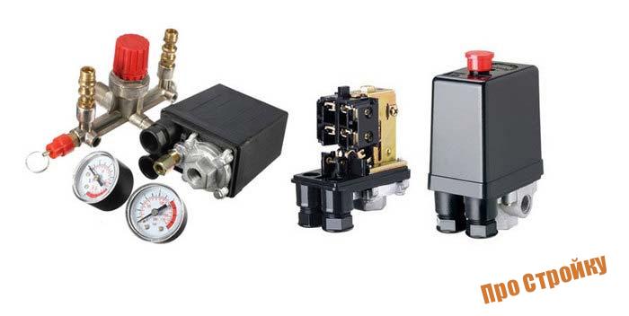
Accessories
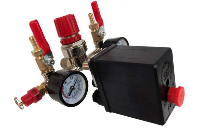
The air compressor relay may contain the following components:
- unloading valve. It is located between the compression chamber and the compressor check valve. When the engine is stopped, this component is activated and removes excess pressure from the piston block. When the engine is started, the pressure generated closes the valve, making it easier to start the unit. Some relief valves have a delayed activation. When starting the engine, it assists the engine by remaining open until the set value is reached in the system. During this time, the engine is gaining maximum speed.
- Mechanical switch. Serves to enable and disable automation. The switch usually has two positions. When the mode is on, automatics are activated, the compressor is connected to the network and turned off, taking into account the specified pressure parameters in the system. In the off position, no power is supplied to the drive.
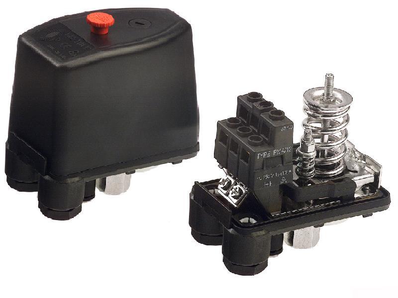 Air Compressor Pressure Switch
Thermal relay. It protects the motor by limiting the current so that the motor windings do not burn out. The required current strength is set using the regulator. If the set value is exceeded, the motor will be disconnected from the network.
Safety valve. Protects the system in case of incorrect functioning of the pressure switch. If the pressure is exceeded, if the relay does not work, then the safety valve turns on, which relieves pressure. This avoids accidents in the event of a control failure.
Some other compressors and their repair
Now screw compressor units are popular among users. There is almost no friction between the rotors in the devices due to the formation of an oil cushion.This design allows the screws to work for a long time. At the same time, the repair of the screw block of the compressor is practically not required, only the bearings wear out.
If a development appears on the screws, then there is little time left before the block is jammed. Repair of screw compressors in such cases consists in replacing blocks.
Centrifugal compressors are dynamic devices, they are used to provide air exchange in mines. The main elements of such a unit are a rotor, an impeller with blades and a diffuser or an annular outlet. From the reliability of the lubrication system in a centrifugal compressor. Turbine compressor oil is used to lubricate centrifugal machines.
Repair of centrifugal compressors should be carried out by employees of service centers, as this is a complex and expensive equipment.
The scroll compressor is a displacement type blower. It consists of two spiral plates inserted one into the other. Repair of scroll compressors is also best done by a service master due to the complex hermetic design.
The most common air conditioner compressor problems are:
- noises (crack, knock);
- leakage;
- performance loss.
The presence of noise in the supercharger is easily repaired. More often Total
extraneous sounds in the device become a sign of problems in the bearing. The item is replaced or repaired. Depressurization is also not a serious problem.
Repairing a car air conditioner compressor is not a difficult task.
WATCH THE VIDEO INSTRUCTIONS
Schemes for connecting the pressure switch to the compressor
The connection of the relay that controls the degree of air compression can be divided into 2 parts: the electrical connection of the relay to the unit and the connection of the relay to the compressor through the connecting flanges. Depending on which engine is installed in the compressor, 220 V or 380 V, there are different schemes for connecting the pressure switch. I am guided by these schemes, subject to the availability of certain knowledge in electrical engineering, you can connect this relay with your own hands.
Connecting the relay to a 380 V network
To connect automation to a compressor operating from a 380 V network, use a magnetic starter. Below is a diagram of connecting automation to three phases.
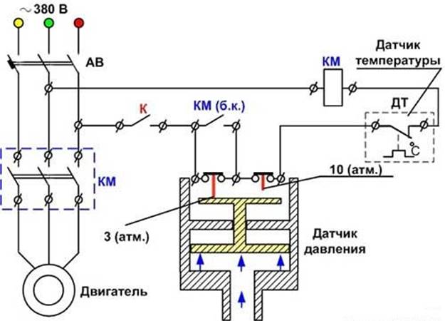
In the diagram, the circuit breaker is marked with the letters “AB”, and the magnetic starter is marked with “KM”. From this diagram, it can be understood that the relay is set to a switch-on pressure of 3 atm. and shutdowns - 10 atm.
Connecting the pressure switch to a 220 V network
The relay is connected to a single-phase network according to the diagrams given below.
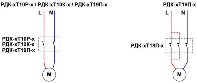
These diagrams show various models of pressure switches of the RDK series, which can be connected to the electrical part of the compressor in this way.
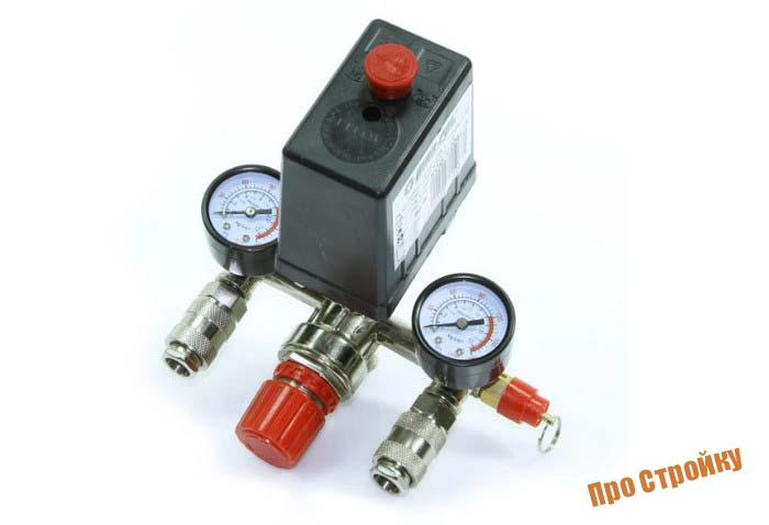
Connecting the pressure switch to the unit
Connecting the pressure switch to the compressor is quite simple.
- Screw the pressure switch onto the receiver nozzle using its central threaded hole. For better sealing of the threads, it is recommended to use fum-tape or liquid sealant. Also, the relay can be connected to the receiver through a gearbox.
- Connect to the smallest output from the relay, if available, an unloader valve.
- Either a pressure gauge or a safety relief valve can be connected to the remaining outputs from the relay. The latter is mandatory. If a pressure gauge is not required, then the free outlet of the pressure switch must be plugged with a metal plug.
- Further, wires from the mains and from the engine are connected to the sensor contacts.
After the complete connection of the pressure switch is completed, it is necessary to set it up for correct operation.
Why does pressure drop occur in the accumulator
Most likely, the pressure drops due to air leakage. The reason is in the pressure line itself.Repair of an electric compressor consists of a thorough inspection of the pipeline. To do this, prepare a soap emulsion and coat the joints in the pipeline. If a leak is found, it is treated with sealing tape.
The air outlet cock of the receiver is capable of passing air when it is loose or has become unusable.
The piston head of the compressor is equipped with a control valve, which can also cause the device to malfunction. The cylinder head is disassembled, but air is first released from the accumulator. If this operation does not help, then the valve must be replaced.
Scheme and device
The device is divided into the following types:
- Starting the electric motor of the compressor when the pressure drops below the set value (normally closed);
- Switching off the engine when the air pressure rises above the normal mark (normally open).
Springs are considered to be the actuating element in the device. Their compression force is measured using a special screw. As a rule, manufacturers adjust the compression force of the springs in such a way that the pressure in the pneumatic network is in the region of 4-6 at. This parameter is always exactly indicated in the instructions.
The pressure switch provides for 2 mandatory subassemblies in its design - a mechanical switch and an unloading valve. The mechanical switch protects against accidental starting of the engine, thus performing the stand by function. After pressing the drive of the device starts, after which the compressor starts to work in automatic mode. Without pressing the button, the electric motor will not work even with reduced pressure in the pneumatic network.
The unloader valve is connected to the air supply line between the compressor and the receiver and is responsible for the operation of the engine. When the compressor drive is turned off, the unloader valve on the receiver disposes of excess compressed air, thus saving the moving parts from the extra effort required to restart the compressor. This prevents the motor from being overloaded with torque. When the unloaded engine is turned on, the valve is closed, which prevents the creation of excess load.
For greater safety, the pressure switches are additionally equipped with safety valves, which are very useful, for example, in case of piston breakage, sudden stop of the electric motor and in any other emergency!
Conclusion
The compressor is easier to maintain immediately after commissioning.
It is easy to avoid errors in operation if you carefully study the instructions for the device:
- Before starting the unit, check the compressor oil and top up if necessary.
- Every 16 hours of operation, drain the moisture from the receiver.
- Every 2 years it is worth inspecting the check valve on the compressor.
- The presence of grounding of non-current-carrying parts is mandatory.
Compliance with such requirements and careful attention to the compressor will reduce the cost of operating the device.
Common Compressor Faults
PISTON COMPRESSORS
SCREW COMPRESSORS