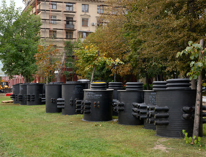
Septic tank with drainage system
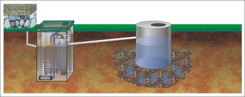
This is a more advanced version of wastewater treatment. The difference from the previous type is that the clarified water does not go directly into the ground from the drainage well, but spreads over the drains over a larger area. Post-treatment in this case is about 98%.
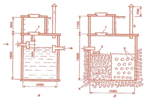
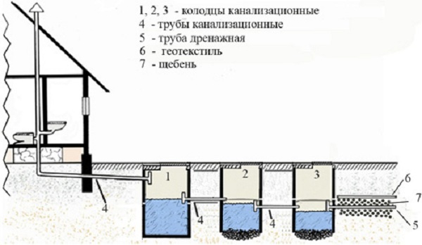
This method is more environmentally friendly, but it requires large land areas. The septic tank in this option is done as follows (sewer wells are a typical project).
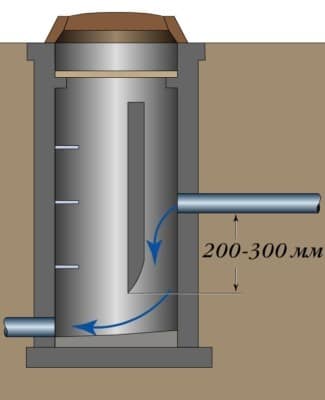
In the first chamber, sewage is settled and divided into fractions. In the second, water clarification occurs with the deposition of mineral sediment on the bottom. The upper bridge prevents foam from entering the cleaner second chamber, the bottom bridge separates the sludge and mineral sediment. After such preparation, already sufficiently clarified water enters the drains and is filtered by the soil.
Drains are perforated drainage pipes that can be purchased commercially or made from a regular sewer pipe. Drains are placed on 20 cm of rubble and are also covered with rubble from above.
And this type of sewer wells SNIP prescribes to have.
So:
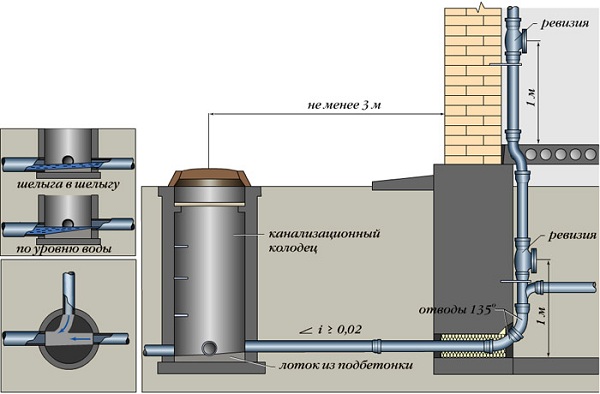
- No closer than 5 m from the house.
- Not closer than 2 m from the fence (the edge of the site).
- Between the septic tank and the well with drinking water, the distance is at least 50 m.
- From the bottom of the septic tank to the upper level of groundwater, the distance is at least 1 m.
If the work on the improvement of the site is carried out by builders, then they compile a table of sewer wells, where all information about the wells is entered.
The arrangement of the drainage system involves the installation of a sewer well. This element of the treatment design plays a key role in repair work and preventive measures such as pumping, flushing and cleaning. The key to the smooth operation of the system is the competent calculation of the volume and depth of the storage tanks and the correct installation. Consider how to determine the height of the sewer well and calculate the volume of the tanks.
- plastic;
- bricks;
- monolithic concrete;
- concrete rings;
By choosing the right tank of the right size, the owner of the site saves himself from the problems associated with the operation of the facility.
If you focus on the purpose of sewer tanks, then they are of several types.
Lookouts
Inspection wells are shafts equipped with a chamber inside, in the walls of which the incoming and outgoing pipes are connected by arranging a special tray. They are designed to control the treatment plant.
The main difference in the design is that the collector and the pipe of the drainage pipeline in it replace the open tray
Through the inspection structures, free access to the pipeline is provided for the implementation of preventive measures, as well as the necessary repair work. They are installed on long straight sections and at junctions where the pipeline changes direction or slope. Depending on this, linear and rotary structures are distinguished.
Variable
The main function of such wells is to level the differences in the height of the treatment facilities if this figure exceeds the permissible level.
The installation of a differential tank allows you to combine pipelines into one network and connect sewer pipes above the level of the trays. With their help, you can solve several problems at once:
- Prevent high sewage velocity due to the elevation of the terrain.
- Connect sewer outlets and deep underground collectors.
- Draw a sewer line around the intersections of underground structures.
Depending on the internal structure, overflow wells can have a multi-stage staggered design, and can also be equipped with fast currents to accelerate slowing down flows or a fender and spillway wall.
Cumulative
Storage tanks are a modern modification of cesspools.
Storage wells accumulate runoff
Sealed containers need periodic cleaning of the contents, which can be done by involving special equipment.
Designed to clean wastewater from debris and heavy suspensions. Filtration tanks are installed in cases where the site is located on sandy and sandy loamy soil types.
The main condition for installing a filtration well is groundwater below the base by at least 1 meter
Manufacturers of wastewater treatment plants for domestic use offer a wide range of filtration tanks designed for different volumes.
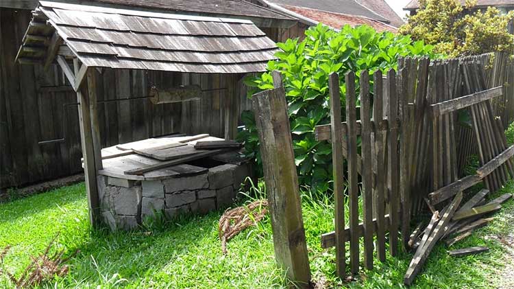
Cesspool without a bottom
This is the "grandfather" version. To date, it is prohibited by the norms of the sanitary and epidemiological station
. However, it is believed that per day the soil is able to process and secure up to 1 meter of cubic wastewater. Therefore, this type of well is possible in garden plots for a toilet, in summer cottages where you do not live permanently.
According to SNIP, sewer wells must meet the requirements.
So:
- The level of the water well should be higher in the landscape than the level of the drain pit.
- The distance from the house to the pit is at least 5 meters, from the pit to the well with drinking water is at least 50 meters, from the pit to the fence is at least 1 meter.
- The distance from the bottom of the pit to the upper groundwater level is at least 1 meter.
- The daily volume of wastewater is not more than 1 cubic meter.
- The volume of the pit is defined as 3 volumes of daily effluents (3 mcub).
Build such a pit as shown in the figure above. The bottom is covered with sand (20 cm), then gravel (20 cm) is poured. This is necessary to filter runoff into the soil, and so that the bottom does not harden. The walls are erected from any sealed material, often improvised: tires, barrels, tanks. Brick or concrete rings are excellent for this purpose. The upper part is closed from precipitation and flood waters. We will discuss construction in more detail in the next subsection.
Types of storm wells
Storm sewage chambers and wells can be made of concrete (reinforced concrete is most often used) or plastic.
Depending on the purpose, storm sewer wells are divided into:
- Absorption or filter well. Such a structure has no bottom. Since the well is located on a plot below the groundwater level, the liquid entering it is filtered and then goes into the ground;
The principle of operation of the absorption well
- Foster. It is located in areas where groundwater is high. Water entering such a well can be used further, for example, for watering plants. Various pumps are used to extract water from a receiving well.
- Drop well. It is installed in places where there are strong differences in ground level. Such a well avoids the formation of a powerful stream of water that can disable the storm system.
Drop well smooths out ground level fluctuations
Carrying out water treatment
After carrying out any work inside the well or if unpleasant changes in water quality are detected, disinfection is carried out. Typically, this procedure is carried out using a solution of bleach 3% concentration. Such a composition is sold in finished form, but you can cook it yourself.
The preparation of this antiseptic includes the following stages:
- 300 g of bleach is poured into a small amount of cold water to a mushy consistency and thoroughly mixed to eliminate all lumps (lumps can retain hypochlorites, chlorides and calcium hydroxide, which can degrade water quality).
- The prepared gruel is diluted with cold water in a volume of 10 liters with stirring, after which it settles for 2-4 hours in a cool place.
- A clear liquid is used, which is filtered through gauze folded in several layers.
The walls of the shaft are disinfected, on which the solution is applied using a spray gun. The water itself is also treated with such a composition. To do this, a solution is simply poured into the well at the rate of 10 liters of the mixture per 1 cubic meter of water. After treatment, the mouth of the well is tightly closed with a lid and kept in this state for 22-25 hours. At the end of the event, the water is completely pumped out of the well shaft.
Regulatory documentation
The main document regulating the requirements for the design, manufacture and operation of cable wells are TU 45.1418-89 Viewing devices for communication cable ducts KKS. The period of operation of these specifications has been extended without indicating the expiration date. It is allowed to use other approved and valid specifications, including TU-5855-001-92718053-2012.
Terminology and basic concepts that are mandatory for use when creating regulatory documentation are contained in GOST R 50889-96. According to this GOST, a communication cable well should be called a "cable sewer well".
The procedure for organizing cable pipeline networks, the design of cable wells, their placement and selection of their type, the introduction of pipelines into cable sewer wells is regulated by the "Guidelines for the construction of linear structures of local communication networks" (Guidelines for SLSMSS) of the Ministry of Information Technologies and Communications of the Russian Federation.
In the manufacture of KKS, regulatory documentation for components for manholes is also used:
- GOST 8591 76 Manholes for telephone conduit cable wells. Specifications.
- GOST 8020 90 Concrete and reinforced concrete structures for wells of sewer, water and gas networks. Specifications.
Product design
Structurally, the cable communication well is a box-shaped structure made of reinforced concrete, placed in a place that excludes flooding by groundwater. This is an underground room, access to which is carried out from above through a hatch equipped with a cast iron cover.
As a rule, its design is composite and contains 2 structural components - upper and lower. The lower element includes a bottom plate and half of the walls. Often there are designs that include a pit and a drainage hole in the bottom. The top element contains the top plate having a hatch hole and the second half of the side walls.
Both elements have metal loops coming out of the concrete mass, used for welding when the product is installed in the ground. On the side walls there are through holes for the entry of cable channels. Many manufacturers, in addition to through holes, make blind niches in the walls with a wall thickness of 30-50 mm, which can be used if it is necessary to increase the number of cable entries.
During the installation of the well, the lower part of the product is buried in the ground, the upper part is mounted on top. By welding the protruding loops, a single structure is formed. After welding, the seam between the elements is sealed with cement mortar.
In addition to prefabricated cable wells, the industry also produces monolithic reinforced concrete products; in this case, there is no need for welding. Cable entries are installed and sealed with crushed brick on cement mortar on both sides of the wall before it is backfilled with soil, and unused niches are covered with mortar.
Complete cable communication well, in addition to the body, contains 1 or more support rings, a manhole cover, a set of mounting cable brackets and ruffs, through which the brackets are mounted. The product is equipped with earrings designed to fasten the unit when pulling cables.
In accordance with the purpose, the wells are produced in several standard sizes in different versions and can have a square, quadrangular or elongated octagonal shape in a horizontal section. Some manufacturers produce products of a different configuration.
Reinforced concrete cable structures are made of high-strength concrete of heavy and medium-weight grades with the use of special additives that increase frost resistance and resistance to anti-icing agents. Despite the improved characteristics of the material, viewing devices are recommended to be mounted in soils that are non-aggressive to concrete.
Regulatory documentation allows the manufacture and operation of cable wells made of bricks, while a typical cable well KKS 1 has a square shape, and wells of other sizes must be built in an oval shape using special equipment.
In the manufacture, it is recommended to use ready-made reinforced concrete floors, for the bottom - reinforced concrete slabs or concrete it in a pit. Ruffs and earrings are mounted in the process of forming the walls. At the end of the masonry, the outer side is protected by a layer of sand-cement plaster.
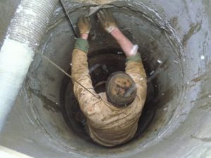
Repair of concrete wells
Currently, the most common design of wells of all types is a column of reinforced concrete rings. The maintenance of such structures has some specific features associated with characteristic damage. The operation of wells (especially deep wells) is accompanied by significant mechanical loads resulting from the movement of layers, the appearance of quicksand, swelling of the soil during freezing, exposure to groundwater and aggressive environments. They lead to various damages that need to be identified and eliminated in a timely manner, which is the main task of servicing wells.
As noted, repair work is divided into scheduled and unscheduled (emergency, and sometimes emergency). Scheduled repairs are aimed at eliminating minor damage and preventing violations. It includes activities such as cleaning the walls from growths and deposits; cleaning or replacement of the filter bottom layer; disinfection of walls and water; pumping water after repair or long downtime; sealing small cracks in concrete.
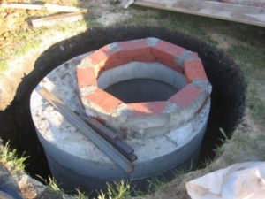
Reinforced concrete rings
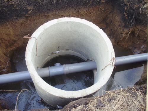
Fast and simple. Sewer well rings are factory-made, you just need to install, process hermetically and connect to the drain
.
We will need:
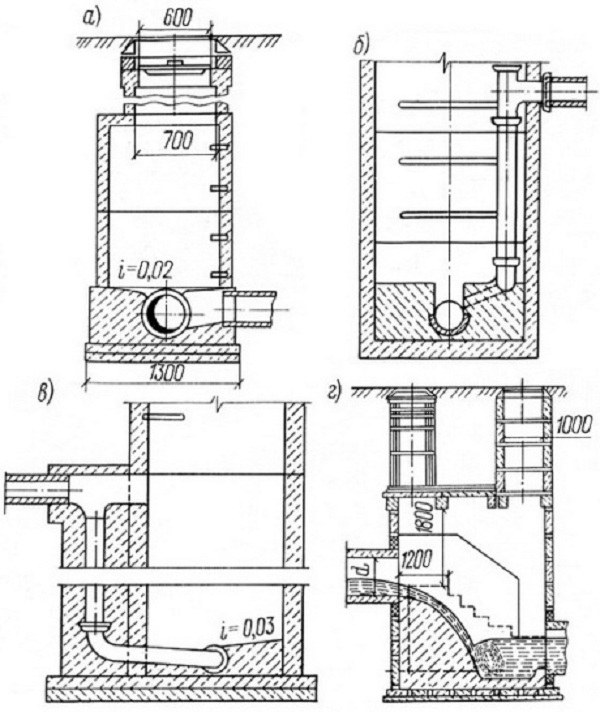
- Reinforced concrete rings. The quantity is calculated as follows: the daily volume of effluents is 600 liters (for example). Multiply by 3, we get 1800 liters or 1.8 cubic meters.
Rings are produced as standard with a height of 0.9 m. The inner diameter varies from 0.7 m to 2 m. Let's calculate the volume of a ring with a diameter of 1 meter. V \u003d 3.14 (pi) * 0.5 * 0.5 (radius squared) * 0.9 (height) \u003d 0.7 m3 Two rings will give a volume of 1.4, which means we need three rings (volume with a margin).
- Reinforced concrete bottom and cover. Ordered with rings.
- Concrete, bitumen, manhole.
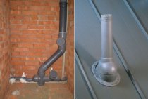
- Ventilation tube.
On a light foundation, install the bottom, then the rings and the lid
Pay special attention to the quality of the joints, the denser they are, the better. Seal joints between structural elements
Insert a sewer pipe into the well.
Coat the inside twice with bitumen for waterproofing. Install sunroof. Install a ventilation pipe with a diameter of 110 mm, a height above the ground of 400-700 mm. Ready.
Brick
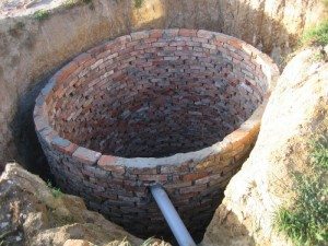
Consider how to build a brick sewer well. It is better to use a clay brick that does not allow moisture to pass through.
.
But ordinary red or silicate is also suitable. Masonry is sufficient to produce half a brick. The shape of the well is recommended to be round for ease of disposal, although a square/rectangular will also work.
The construction of sewer wells from brick will require.
So:
- Brick.
- Floor slab.
- Cement, sand.
- Oily clay, bitumen.
- Rubble.
- Ventilation tube.
We pour the foundation. Composition: sand 2 parts, gravel 1 part, cement 1 part.The height of the foundation depends on the mass of the brickwork. Usually, 20 cm is enough. You can additionally reinforce the foundation. After pouring the foundation, let it harden for 7 days. Water it once a day.
We lay out the brick. We plaster the bottom and walls. Zhelezny. We cover with 1-2 layers of bitumen. Installing the cover. This is either a reinforced concrete slab or a wooden tarred shield.
We install a hatch, a ventilation pipe. Ready. You just have to ensure timely maintenance of sewer wells.
Application of shells
 The meaning of this word has not yet been established. Some experts believe that it is borrowed from Eastern languages, some consider it an old Slavic name. Despite this, products with this name are used in mechanical engineering, construction and the creation of musical instruments. The shell is a hollow cylinder, open at the ends. It is made of metal, wood, plastic.
Metal shells are blanks for the manufacture of boilers, nuclear reactor vessels and strong submarine hulls. The head of the sewer manhole consists of a cover and a shell, i.e. the part on which this cover is installed. These elements, made of polymer concrete, are lighter than cast iron and are successfully used in private areas. They are installed on drainage and manholes, as well as borehole pits. The dimensions of such a drum are equal: Ø out. — 680 mm, Ø int. - 630 mm. The weight of the kit is about 45 kg.
Shells in construction
 For the manufacture of wall well rings, detachable forms are used, consisting of inner and outer shells. On a flat area or metal flooring set the form. The inner and outer drums are interconnected by spacers equal to the thickness of the ring. A reinforcing cage is installed in the space between the elements, which gives the product rigidity. After that, concrete is laid: hard - in layers, plastic - the entire volume at the same time. Compaction is carried out with a reinforcing pin or a platform vibrator installed on the deck. The “hammered” form is left for the concrete to harden. After 3-5 days, it is removed, and the product remains on the site until the material reaches its full strength.
In order to remove the drums and not damage the finished product, they are made detachable and bolted together. The surfaces of the shells in contact with concrete are treated with a special emulsion so that it does not stick to the metal. The most popular are rings with dimensions Ø int. — 1000 mm, Ø out. - 1160 mm, H - 890 mm. In some cases, rings of the same diameter are made, but 400 mm high. They are installed on top to increase the height of the well in the event that an incomplete circle is obtained above the ground.
In the manufacture of stringed musical instruments, the upper and lower decks are attached by means of the shell. Here it is made of bent plywood and is the side part of the tool. A shell is called a shingled or bast rim bent into a ring, the walls of a sieve, a basket, a sieve.
The main advantages of communication wells
All KKS are divided into light and heavy systems. The light ones are placed under the pedestrian zone, the heavy ones - under the roadway. The communication wells are made of high density polyethylene, and the covers for the device are made of cast iron, concrete or HDPE. Without exception, cable systems have the following advantages:
- resistance to low temperatures;
- tightness of the structure;
- the possibility of installation in difficult conditions;
- excellent strength;
- light weight;
- long service life;
- ease of installation, storage and transportation;
- the ability to connect the model to the sewer of a free configuration.
Finally
Wells can be equipped with filters and pumps for supplying water to the house, but in this case you will have to worry about additional insulation, especially at the head.
It is known for certain that sewer systems were used back in the days of Ancient Rome, so the technology for their creation has been worked out, practically, to the smallest detail. There are certain norms and requirements for the arrangement of both the external and internal sewerage systems themselves, and for sewer wells. It is immediately worth noting that all sewer work must be carried out in accordance with the SNiP scheme, which is responsible for the arrangement of sewers, external networks and structures related to this.
In private houses, the installation of sewer SNiP is not possible without special manholes prescribed by the regulations
With the help of this tool, it will be possible not only to control the movement of sewage through the system, but also to carry out cleaning, which is important to carry out several times a year, as prescribed in the requirements of the subsection "SNiP sewer wells"
In addition, the construction of SNiP sewer wells provides for the presence of a manhole even before the entrance of an individual sewer system to a common sewerage network or a centralized collector located outside the building line that separates the building site from the street or roadway. In accordance with SNiP, manholes must be located every 30-40 m with a pipe diameter of 150 mm, and also every 50-55 m with a pipe diameter of 200 mm. In addition, sewer wells SNiP (inspection) must be installed:
- At the corners of the sewer system;
- In places where the diameter of the pipe changes or when it slopes;
- At pipe branches.
The device of sewer wells SNiP is associated with a huge number of requirements not only for the tank, but also for its components.
According to current regulations, SNiP sewer wells can be made from both reinforced concrete and polymeric substances. However, the practice of combining materials is often used, which is why the regulatory authorities set certain requirements for the installation of SNiP sewer wells to be as competent and efficient as possible. According to current legislation, SNiP sewer wells can have the following size:
- 150 mm with a pipeline size of 70 mm or more;
- 1000 mm with a pipeline size of 600 mm;
- 1500 mm with a pipe diameter of 1500 mm;
- Not less than 1500 mm, with a diameter and depth above 3 m.
The device of SNiP sewer wells should begin with earthworks, in other words, marking the ground, digging a pit for the well itself, as well as a trench for connecting a pipeline to it. Before sewer wells SNiP are installed, it is necessary:
- Mark the territory of the location of the wells;
- Demolish trees, bushes and other plants in the territory of land works;
- Demolish structures that interfere with construction;
- Equip a convenient way to the construction site.
After preparing for the installation of SNiP sewer wells, it is necessary:
- open a pit;
- clean the bottom;
- Verify data;
- Equip waterproofing at the bottom of the well (if SNiP sewer wells are made of stone).
- The device of a concrete pillow from concrete M-50;
- Sealing the ends of the pipeline with concrete and bitumen;
- Installation of concrete rings;
- Concrete insulation of the structure itself;
- Pipe fitting;
- The test of the well itself;
- Backfilling of its walls;
- Joint insulation.
This is true if SNiP sewer wells are made of concrete or brick, but recently the construction of SNiP sewer wells made of plastic has become increasingly popular.
The device of SNiP sewer wells made of plastic is much cheaper and more reliable than its stone counterpart. The popularity of such wells is characterized by a reduced amount of excavation, as well as ease of installation, since they are produced according to well-defined pipe standards. At the same time, the material of these same pipes does not play a role, even a master who has undertaken such work for the first time can connect them.
Before building a sewer well, it is necessary to carefully weigh all the positive and negative aspects of one or another option.Basically, for small suburban areas, the Construction of SNiP sewer wells made of plastic will be the best option, since the owner does not have to order heavy equipment and start the laborious and lengthy process of creating a sewer well.