Schema parsing
As you understand, the assembly consists of filters, an elevator, instrumentation and fittings. If you plan to independently engage in the installation of this system, then you should understand the scheme. A suitable example would be a high-rise building, in the basement of which there is always an elevator unit.
In the diagram, the elements of the system are marked with numbers:
1, 2 - these numbers indicate the supply and return pipelines that are installed in the heating plant.
3.4 - supply and return pipelines installed in the heating system of the building (in our case, this is a multi-storey building).
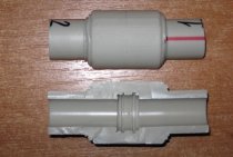
6 - under this figure are coarse filters, which are also known as mud collectors.
The standard composition of this heating system includes control devices, mud collectors, elevators and valves. Depending on the design and purpose, additional elements may be added to the node.
Interesting! Today, in multi-storey and apartment buildings, you can find elevator units that are equipped with an electric drive. Such an upgrade is needed in order to regulate the diameter of the nozzle. Due to the electric drive, it is possible to adjust the heat carrier.
It is worth saying that every year utilities are becoming more expensive, this also applies to private houses. In this regard, system manufacturers supply them with devices aimed at saving energy. For example, now the circuit may contain flow and pressure regulators, circulation pumps, pipe protection and water treatment elements, as well as automation aimed at maintaining a comfortable mode.
Another variant of the thermal elevator node scheme for a multi-storey building.
Also, in modern systems, a thermal energy metering unit can be installed. From the name you can understand that he is responsible for accounting for heat consumption in the house. If this device is missing, the savings will not be visible. Most owners of private houses and apartments seek to install meters for electricity and water, because they have to pay much less.
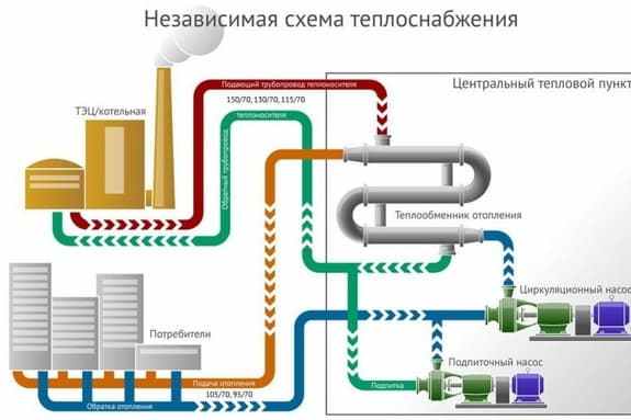
Independent heating system
The principal feature of this system is the presence of an intermediate collection point. In residential private houses, it can be implemented as a control station (including for pressure reduction), but this scheme is made independent by the integration of a heat exchanger. It performs the functions of a rational and balanced redistribution of hot flows, also maintaining, if necessary, an optimal temperature regime. That is, with an independent connection of the heating system, the heating network as such does not act as a direct source of supply, but only directs flows to an intermediate technological point. Further, in accordance with the settings made, in a more targeted version, both drinking water and hot water supply with heating and other domestic needs can be supplied from it.
Common breakdowns of the elevator assembly
The main malfunctions of the heating system elevator can be caused by the failure of the device itself due to clogging or an increase in the inner diameter of the nozzle. Also, the cause of the breakdown may be clogging of the sump. breakage of shutoff valves and failure of the regulator settings.
It is possible to determine the breakdown of the elevator unit of the heating system by the temperature difference before and after the device. If a strong drop is detected, it can be stated that the elevator is broken due to clogging or an increase in the diameter of the nozzle. But regardless of the breakdown, the diagnosis is carried out by certified specialists. When the elevator assembly is clogged, it is cleaned.
If the initial diameter has increased due to corrosion, then there will be a complete imbalance of the entire heating system.At the same time, the radiators in the rooms on the upper floor will not receive thermal energy in full, and the batteries in the lower apartments will overheat greatly. To eliminate the problem, the nozzle is replaced with a new analogue with the required diameter.
It is possible to detect clogging of the mud collectors in the heating elevator unit by changing the readings of pressure sensors located immediately before and after the device. To remove contaminants in the heating system, they are discharged using a tap located at the bottom of the sump. If such actions do not give positive results, then the device is dismantled and mechanically cleaned.
Possible malfunctions
A common malfunction can be called a mechanical failure of the elevator. This may occur due to an increase in the diameter of the nozzle, defects in the valves or clogging of the sump. It is quite simple to understand that the elevator is out of order - there are noticeable temperature drops of the heat carrier after and before passing through the elevator. If the temperature is low, then the device is simply clogged. In case of large differences, repair of the elevator is required. In any case, if a malfunction occurs, diagnostics are required.
The elevator nozzle becomes clogged quite often, especially in areas where the water contains many additives. This element can be dismantled and cleaned. In the case when the nozzle diameter has increased, an adjustment or complete replacement of this element is necessary.
Other malfunctions include overheating of devices, leaks and other defects inherent in pipelines. As for the sump, the degree of clogging can be determined by the indicators of pressure gauges. If the pressure increases after the sump, then the element needs to be checked.
Scheme of the elevator heating unit
In any building, including a private house, there are several life support systems. One of them is the heating system. In private houses, different systems can be used, which are selected depending on the size of the building, the number of floors, climate characteristics and other factors. In this material, we will analyze in detail what a heating unit is, how it works and where it is used. If you already have an elevator assembly, then it will be useful for you to learn about defects and how to eliminate them.
In simple words, a thermal unit is a complex of elements that serve to connect a heating network and heat consumers. Surely readers have a question whether it is possible to install this node on their own. Yes, you can if you can read diagrams. We will consider them, and one scheme will be analyzed in detail.
The updated scheme of heat supply of the municipality of the city of Yekaterinburg until 2030, updating for 2019
Heat supply scheme of the city of Yekaterinburg
Book 1. The current situation in the field of production, transmission and consumption of thermal energy for the purposes of heat supply
Appendix 1. Energy sources of the city Appendix 2. Heat networks of the city Appendix 3. Heat loads of city consumers and heat grid organizations in accordance with the requirements established by the Government of the Russian Federation in the standards for information disclosure by heat supply organizations, heat grid organizations and regulatory bodies
Book 2. Existing and prospective consumption of thermal energy for the purpose of heat supply
Appendix 1. Issued and extended specifications for connection to heating networks
Book 3.An electronic model of the heat supply system of the municipality "city of Yekaterinburg" - is not subject to placement in accordance with clause 19 of the Requirements for the procedure for the development and approval of heat supply schemes, approved by Decree of the Government of the Russian Federation dated February 22, 2012 No. 154
Book 4. Existing and prospective balances of thermal power of thermal energy sources and thermal load
Appendix 1. Zoning of district heating systems until 2030. Hydraulic calculations Appendix 2. Zoning (graphic part)
Book 5. Master plan for the development of heat supply systems
Book 6
Book 7. Proposals for the construction, reconstruction and technical re-equipment of thermal energy sources
Book 8. Proposals for the construction and reconstruction of heating networks
Book 9
Book 10. Prospective fuel balances
Book 11. Assessing the reliability of heat supply
Book 12. Justification of investments in construction, reconstruction and technical re-equipment
Book 13. Indicators of the development of heat supply systems
Book 14. Price (tariff) consequences - not subject to placement in accordance with paragraph 19 of the Requirements for the procedure for the development and approval of heat supply schemes, approved by Decree of the Government of the Russian Federation of February 22, 2012 No. 154
Book 15
Annex 1. Graphic part
Book 16
Book 17
Book 18
Mixing coefficient values
Estimated temperature in the heating network, °С
Estimated temperature in the heating system, °С
Normal operation of the elevator occurs at H/h = 8-12 (H is the available pressure at the inlet; h is the resistance of the heating system).
It should be borne in mind that the value of the calculated pressure in front of the elevator is directly proportional to the resistance of the heating system. Therefore, an increase in the resistance of the heating system, for example, by 1.5 times will cause an increase in the calculated pressure R also by 1.5 times.
Connection with a pump on a jumper (c). In the event that water mixing cannot be performed using an elevator, install a pump on the jumper between the supply and return pipelines of the heating system. Mixing with the help of an elevator cannot be performed for the following reasons: the pressure at the connection point is insufficient for its normal operation; the required thermal power of the mixing unit is large and goes beyond the power of manufactured elevators (usually more than 0.8 MW - 0.7 Gcal / h).
When installing mixing pumps in residential and public buildings, it is recommended to use silent, foundationless pumps. When installing mixing pumps designed for high flow, centrifugal type K and KM are used as mixing pumps. Pump flow is G2=1.1G1, and the pressure should be equal to H = 1.15h (where h is the resistance of the heating system).
Connection with a pump on the supply pipe of the heating system (d). A supply pipe pump is installed if, in addition to mixing water, it is necessary to increase the pressure in the supply pipe at the connection point of the heating system (the static height of the heating system is higher than the pressure in the supply pipe at the connection point).
Pump flow is G3 = 1.1 (1 + U)G1, and the pressure should be equal to:
where h is the resistance of the heating system; hn - the difference between the static height of the heating system and the piezometric height in the supply pipeline of the heating network at the point of connection, m.
Connection with a pump on the return pipeline of the heating system (d). The pump on the return pipe is installed if, along with mixing water, it is necessary to reduce the pressure in the return pipe at the point of connection of the heating system (the pressure is higher than that allowed for the heating system). The pump flow in this case is C3 = 1.1 (1 + U)G1 and the pressure must have a value that provides the required pressure in the return pipeline.
Independent connection (e). If the pressure in the return pipeline in the heating network is higher than the allowable pressure for the heating system, and the building has a significant height or is located in a high place in relation to adjacent buildings, then the heating system is connected according to an independent scheme.
According to an independent scheme, it is allowed to attach buildings with a height of 12 floors or more. The independent scheme is based on the separation of the heating system from the heat network using a heat exchanger, as a result of which the pressure in the heat network cannot be transferred to the heat carrier of the heating system. The circulation of the coolant is carried out with the help of circulation pumps of the K and KM types. The pump flow is determined by the formula
where Q is the power of the heating system, kJ/h (Gcal/h); C is the heat capacity of water, J/(kg h); T11,T22 - design water temperature, respectively, in the supply and return pipelines of the heating system, ° С
It happens that private houses located within the city are located next to the laid district heating networks, and some are even connected to them. Of course, at the present time, the priority is individual heating, and centralized heating is gradually becoming a thing of the past. But if the house is already connected to the network or there are problems with the autonomous system, then you need to use what is available. For joint operation of the heat source with consumers, a dependent and independent heating system is used. What they are, as well as the pros and cons of both schemes will be outlined in this material.
Independent heating system
In an independent heating system, the district heating network and the heat distribution systems are hydraulically separated. In the heating network, the heat carrier is heated, and then it enters the individual heat points of consumers.
The centralized independent system has a real and calculated temperature graph. In a real graph, the temperature depends on weather conditions. If there are no big frosts, then the temperature of the heat carrier will be much lower than the calculated one. The calculated schedule has a maximum coolant temperature and can be 105/70oC or 95/70oC.
In the heat exchanger, the primary coolant transfers heat to the secondary. It circulates through each of the systems.
Fluid that passes through the mains does not enter the house. Heating is obtained by heat transfer.
Consider the advantages of an independent heating system:
- The use of coolant of different temperatures.
- It is possible to flexibly and accurately adjust the temperature in each heat distribution network.
- The dependent scheme is 40% more expensive to operate than the independent scheme.
- Long service life.
The disadvantage is only a high cost in construction.
Independent closed heating system
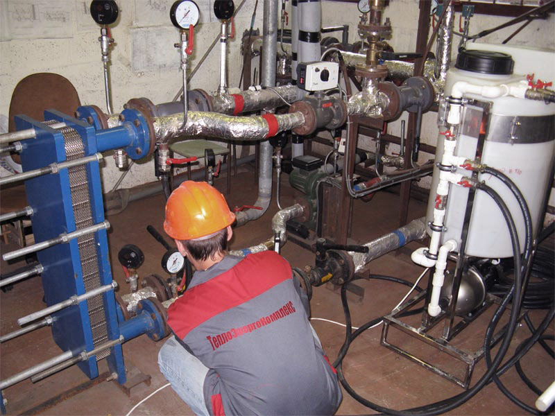
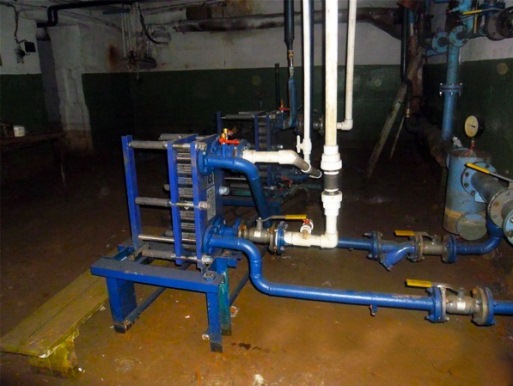
At present, when installing new boiler houses, an independent scheme for connecting the heating system has become more often used. It has a main and an additional circulation circuit, hydraulically separated by a heat exchanger. That is, the coolant from the boiler house or CHP goes to the central heating point, where it enters the heat exchanger, this is the main circuit. An additional circuit is a house heating system, the coolant in it circulates through the same heat exchanger, receiving heat from the network water from the boiler room. The scheme of operation of an independent system is shown in the figure:
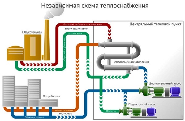
But what about the centralized supply of hot water, because now it is impossible to take it from the main, the temperature is too high there (from 105 to 150 ºС)? It's simple: an independent connection scheme allows the installation of any number of plate heat exchangers connected to the main pipelines. One will provide heat to the heating system at home, and the second can prepare water for household needs. How this is implemented is shown below:
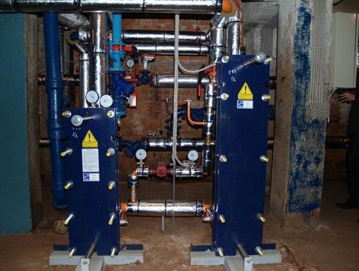
To ensure that hot water always arrives at the same temperature, the DHW circuit is closed with the organization of automatic make-up in the return pipeline. In apartment buildings, the DHW circulation return line can be seen in the bathroom, heated towel rails are connected to it.
Obviously, the operation of an independent heating system has a lot of advantages:
- the home heating circuit does not depend on the quality of the external coolant, the condition of the main networks and pressure drops. The entire load falls on the plate heat exchanger;
- it is possible to regulate the temperature in the rooms with the help of thermostatic valves;
- the coolant in a small circuit can be filtered and cleaned of salts, the main thing is that the pipes are in good condition;
- in the DHW system there will be drinking-quality water entering the house through the water main.
However, due to the dirty low-quality coolant in the central network, periodic flushing of an independent heating system, or rather, a plate heat exchanger, will be required. Fortunately, this is not so difficult to do. Another disadvantage is the higher costs for the purchase of equipment, namely: heat exchangers, circulation pumps and shut-off and control valves. But a closed system is more reliable and safer than an open one, it meets modern requirements more and is better adapted to new equipment.
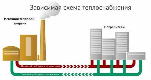
Dependent heating system
A dependent system is often called an open system. And it is called so, because a heat carrier is taken from the supply pipe to provide the house with hot water. The dependent scheme is often used in administrative, multi-apartment and other buildings that are intended for general use. A feature of an open system is that the coolant flows through the main networks and enters the house immediately.
If the temperature of the heat carrier in the supply pipeline is not more than 95 ° C, then it can be directed to heating devices. But if the temperature exceeds 95 ° C, then it is necessary to install an elevator unit at the entrance to the house. With its help, the water that comes from the heating radiators is mixed into the hot coolant to lower its temperature.
Previously, no one paid special attention to the flow rate of the coolant, so this scheme was often used. Dependent heating system does not require large installation costs
To provide the house with hot water, there is no need to lay additional pipes.
But in addition to the above advantages, one can also distinguish the disadvantage of a dependent heating system:
- It is problematic to adjust the temperature regime in the premises. Valves quickly fail due to the poor quality of the heat carrier.
- From the main pipes, various dirt and rust enters the heating radiators. Steel and cast iron radiators continue their work without any changes. But in aluminum batteries, the ingress of rust and dirt adversely affects the work.
- Although the coolant passes all the required desalination and purification, it still passes through rusty main pipelines. Accordingly, the coolant cannot be of good quality. This factor is a big disadvantage, since the coolant is used for water supply.
- Due to repair work, pressure drops in the system or even water hammer often occur. Such problems can seriously affect the operation of modern heating radiators.
Cons of an independent heating system
Of course, the introduction of additional regulatory and instrumentation equipment into the infrastructure will cost a lot. If we take into account the use of a boiler or radiator with the support of a circulation pump as the main heating unit, then we can talk about 500-700 thousand rubles. In this respect, dependent and independent heating systems diverge radically. By the way, a dependent connection can do without tangible costs. Another thing is that in a private house, owners usually introduce fairly efficient boilers and boilers into the network. In addition, high security requirements are also noted among the shortcomings. This does not mean that a stand-alone circuit with several layers of piping is in itself a great danger, but expanding the network with connection to a dozen intermediate devices imposes a great responsibility on the user when operating the system.
Dependent lines for connecting coolants are now perceived as obsolete, and independent ones as a more functional, balanced and ergonomic solution. But what heating system is suitable if we are talking about an average private house with a typical amount of energy consumption? Initially, you can focus on certain configurations of independent systems, but do not forget about the following nuances:
- If there are technical difficulties in arranging heating equipment, then a dependent system will be more justified.
- If periodic power outages are observed, then an autonomous generator will have to be purchased along with the heat exchanger.
- The longer the heating period lasts, the more profitable the transition to a dependent system will be.
- For dachas and, in principle, low-cost objects in terms of thermal energy, in the long term, it is advisable to make a choice in favor of an independent connection.
Comparison of solutions
A dependent scheme for connecting heating has, in essence, only one advantage, but a very important one - the cheapness of implementation. An elevator assembly for a small cottage can be assembled with your own hands from consumer-grade valves
Noticeable against the background of distributing batteries around the house will be only the price of manufacturing a nozzle - the only exclusive one made, the diameter of which determines the thermal power of the elevator.
What is the asset of an independent scheme?
Incomparably more flexible temperature control of the heat carrier for the heating system. It is enough just to reduce the flow of coolant through the heat exchanger - and the house will become colder.
- The practical consequence of the flexible adjustment of heating to the needs of the house is efficiency. Relative to the dependent system, it is estimated at 10-40 percent.
- Finally, the main thing: in a dependent system, we are forced to use water with a lot of pollution. It carries sand, scale and a lot of mineral salts.
We are not talking about the use of water as drinking water, moreover, in some regions it is even undesirable to wash with hot tap water. An independent circuit makes it possible to use purified water or even non-freezing coolants as a coolant.
For the needs of hot water supply, it is not a problem to heat drinking water.
Alternative thermal scheme
Automated system
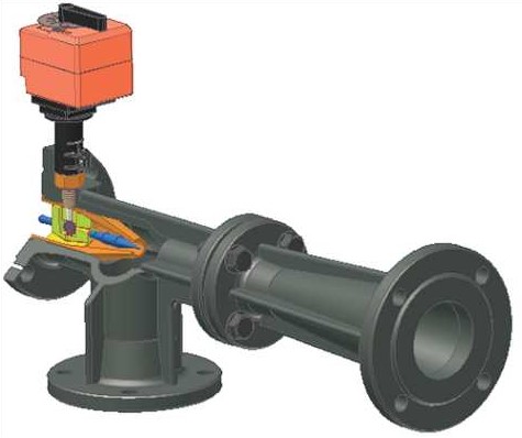
The main purpose of the automated unit is to control the temperature regime and the flow rate of the coolant inside the heating system, depending on the temperature outside it. For the operation of such a node, it is necessary to have a source of electricity of sufficient power. But, despite all the innovations in the field of heating technologies, the elevator unit is still popular in utility organizations.
To date, elevators in the heating system with an electric adjustment drive are popular. In addition, it becomes possible to control the flow of the coolant without human intervention.Due to the fact that such equipment has undeniable advantages, there are no prerequisites that utilities will replace it in the near future.
Comparison for reliability and durability
The practice of operating technically complex and multilevel systems shows that they are less maintainable and more often must be subjected to preventive inspections with maintenance measures. It cannot be said that the independent connection of the heating system reduces the overall level of reliability and safety (in some cases even increases), but the tactics of carrying out repair and restoration measures should be at a different and more responsible level.

At a minimum, an increase in labor and time resources will be required when inspecting the heat exchanger and adjacent piping. Possible uncontrolled accidents at this node can lead to damage to the pipeline. Therefore, experts recommend installing several sensors with pressure, temperature and tightness control. The latest collector cabinets also provide for the use of self-diagnostic complexes for continuous monitoring of the system status. As for the closed heating infrastructure, such control and measuring fittings will also not be superfluous for it, but in this case its need is not so high.
Notification of JSC SIBEKO on the start of updating the heat supply scheme of the city of Novosibirsk until 2030 as of 2017
JSC "SIBEKO" has started updating the "Heat supply scheme for the city of Novosibirsk until 2030" for 2017 in accordance with the Decree of the Government of the Russian Federation dated February 22, 2012 No. 154 "On the requirements for heat supply schemes, the procedure for their development and approval."
In accordance with the Decree of the Government of the Russian Federation dated February 22, 2012 No. 154 “On the requirements for heat supply schemes, the procedure for their development and approval”, the mayor’s office of the city of Novosibirsk began updating the heat supply scheme for the city of Novosibirsk until 2030 as of 2017.
Notifications on the development of a project for updating the heat supply scheme of the city of Novosibirsk until 2030 as of 2017 are accepted at the address: Novosibirsk, st. Trudovaya, 1, email address: gbelova@admnsk.ru, telephone 228-88-56, fax 228-88-10.
In accordance with Decree of the Government of the Russian Federation dated February 22, 2012 No. 154 “On the requirements for heat supply schemes, the procedure for their development and approval”, the mayor’s office of the city of Novosibirsk posted on the website of the Department of Energy, Housing and Communal Services of the city a project to update the heat supply scheme of the city of Novosibirsk until 2030 according to as of 2015.
Comments and proposals on the project for updating the heat supply scheme of the city of Novosibirsk until 2030 are accepted until 04/02/2014 at the address: Novosibirsk, st. Trudovaya, 1, email address: gbelova@admnsk.ru, mslashinin@admnsk.ru, telephone 228-88-91, 228-88-94, fax 228-88-03.
Notifications about the beginning of the development of a project for updating the heat supply scheme of the city of Novosibirsk until 2030 are accepted until 06/03/2013 at the address: Novosibirsk, st. Trudovaya, 1, email address: gbelova@admnsk.ru, dbruzgin@admnsk.ru, telephone 203-57-47, fax 222-54-32.
The mayor's office of the city of Novosibirsk announces the start of updating the heat supply scheme for the city of Novosibirsk until 2030 as of 2015. Notifications about the beginning of the development of a project for updating the heat supply scheme of the city of Novosibirsk until 2030 are accepted until 06/03/2013 at the address: Novosibirsk, st. Trudovaya, 1, email address: gbelova@admnsk.ru, dbruzgin@admnsk.ru, telephone 203-57-47, fax 222-54-32. Additionally, we inform you that the heat supply scheme for the city of Novosibirsk until 2030 as of 2014, after updating, was sent for consideration to the Ministry of Energy of the Russian Federation.