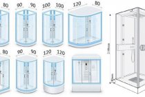
Features of connecting to a hot water supply system
If a separate outlet is used for the towel dryer (serial connection to the hot water supply system), and the water from it is discharged through sources inside the apartment, then the installation of the heated towel rail for hot water is carried out without additional work. But with this connection of the dryer for towels, the temperature of hot water decreases. It is usually used in small houses.
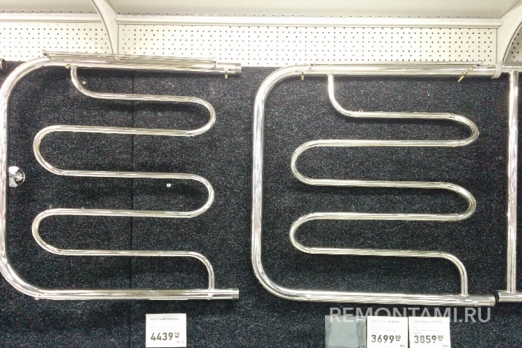
Prices for dryers of different types in the store
More often, the device is connected to the water supply, replacing part of the riser, this can be seen in the bathroom in a panel house. When installing a heated towel rail on a hot water riser, additional insurance in the form of a bypass is required.
Plate heat exchangers applications
Plate heat exchangers are used in the home heating system, hot water supply, air conditioning systems in large cottages, schools, gardens, swimming pools, in entire microdistricts, as well as in the heating system of rural houses. Plate heat exchangers are widely used in the food industry.
Heat exchangers for heating have a number of undeniable advantages compared to other devices used to create a suitable microclimate.
Such heating devices have a number of advantages over other types.
Positive traits
Among the main positive qualities of a device that provides heating, the following can be noted:
- high level of compactness;
- plate heat exchangers have a high heat transfer coefficient;
- the heat loss coefficient is as low as possible;
- pressure losses are at a minimum;
- installation and adjustment, repair and insulation works require low financial costs;
- in case of possible clogging, this device can be disassembled, cleaned and assembled back in just 2 workers after 4-6 hours;
- it is possible to add power to the plates.
https://youtube.com/watch?v=pOTVV58Rj3U
In addition, due to its simplicity, the connection of the heat exchanger to the heating system can be carried out simply on the floor in the substation or on the usual supporting structure of the block substation. Separately, it is worth noting the low level of contamination of the surface of the heat exchanger, which is caused by the high turbulence of the liquid flow, as well as due to the high-quality polishing of the heat exchange plates used. Today, the life of the sealing gasket from leading European manufacturers is at least 10 years. The service life of the plates is 20-25 years. The cost of replacing the sealing gasket can be 15-25% of the total cost of the entire unit.
It is very important that after carrying out a detailed calculation, the design of a modern plate heat exchanger can be changed according to the characteristics required and specified in the terms of reference (design variability and task variability). Absolutely all plate heat exchangers are resistant to high levels of vibration
In modern devices of the heating system, the consequences of possible water hammer are reduced to almost zero.
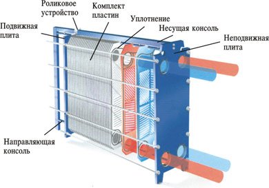
What is a modern heat exchanger made of?
A modern type heat exchanger consists of several parts, each of which plays its own important role:
- a fixed plate, to which all inlet pipes are connected;
- pressure plate;
- heat transfer plates with inserted gaskets of sealing type;
- top and bottom guides;
- rear rack;
- threaded studs.
This image shows a shell and tube heat exchanger.
Thanks to this unique design, the heat exchanger is able to provide the most efficient layout of the entire surface of the used heat exchanger, which makes it possible to create a small heating apparatus. Absolutely all the plates in the assembled package are the same, only some of them are turned to the other at an angle of 180 degrees. That is why channels must be formed during the necessary contraction of the entire package. It is through them during the heating process that the working fluid flows, which takes part in heat transfer. Thanks to this arrangement of the elements of the system, the correct alternation of channels is achieved.
Today, we can safely say that plate-type heat exchangers are more popular due to their technical characteristics. A key element of any modern heat exchanger is the heat transfer plates, which are made of steel that is not subject to corrosion, the thickness of the plates is in the range from 0.4 to 1 mm. For production, a high-tech stamping method is used.
During operation, the plates are pressed against each other, thereby forming slotted channels. The front side of each of these plates has special grooves, where a rubber contour gasket is specially installed, which ensures complete tightness of the channels. There are four holes in total, two of them are necessary to ensure the supply and removal of the heated medium to the channel, and the other two are responsible for preventing cases of mixing of the heating and heated media. In the event of a break in one of the small circuits, the plate heat exchangers are protected by drainage grooves.
If there is a large difference in the flow rate of the media and a very small difference in the final temperatures, then it is possible to reuse the heat exchange process, which will occur through a loop-like flow direction.
Two-stage sequential circuit.
Network
water branches into two streams: one
passes through the flow regulator PP, and
second through heater second
steps, then these streams mix
and enter the heating system.
At
maximum return water temperature
after heating 70ºС
and
medium load hot water supply
tap water is practically
warms up to normal in the first stage,
and the second stage is completely unloaded,
because temperature controller RT closes
valve to the heater, and the entire network
water flows through the flow regulator
PP into the heating system, and the system
heating receives more heat
calculated value.
If
return water has after system
heating temperature 30-40ºС
, for example, at positive temperature
outdoor air, then water heating in
the first stage is not enough, and it
warmed up in the second stage. Another
a feature of the scheme is the principle
related regulation. the essence of it
consists in setting the flow controller
to maintain a constant flow
network water for subscriber input to
overall, regardless of the load of hot
water supply and regulator position
temperature. If the load on the hot
water supply increases, then the regulator
temperature opens and passes
through the heater more network
water or all network water, while
reduced water flow through the regulator
flow, resulting in temperature
network water at the entrance to the elevator
decreases, although the coolant consumption
remains constant. Warmth not given
during a period of high load of hot
water supply, compensated during periods
low load, when the elevator enters
elevated temperature flow. decline
air temperature in the rooms
happens because used
heat storage capacity
building envelope structures. This and
is called coupled regulation,
which serves to equalize the daily
uneven load hot
water supply. During the summer, when
heating off, heaters
are put into operation in sequence with
using a special jumper. This
the scheme is applied in residential, public
and industrial buildings at a ratio
loads
The choice of scheme depends on the schedule of the central
heat supply control: increased
or heating.
advantage
consistent
circuits compared to two-stage
mixed is alignment
daily schedule of heat load,
better use of the coolant,
which results in a reduction in water consumption.
online. Return of network water from low
temperature improves the heating effect,
because can be used to heat water
low pressure steam extractions.
Reducing the consumption of network water for this
scheme is (at the heat point)
40% compared to parallel and 25% to
compared to mixed.
Flaw
- inability to complete
automatic control of thermal
item.
Dependent scheme with a three-way valve and circulation pumps

Dependent scheme for connecting a heating substation of a heating system to a heat source with a three-way valve for a heat flow regulator and circulation-mixing pumps in the supply pipeline of the heating system.
This scheme in ITP is used under the following conditions:
1 The temperature schedule of the heat source (boiler room) is greater than or equal to the temperature schedule of the heating system. The heat point connected according to this concept can work both with admixture to the flow from the return pipeline, and without it, that is, let the coolant from the supply pipeline of the heating network directly into the heating system.
For example, the calculated temperature curve of the heating system 90/70°C is equal to the temperature curve of the source, but the source, regardless of external factors, always works with an outlet temperature of 90°C, and for the heating system, it is necessary to supply a coolant with a temperature of 90°C only at the calculated outside air temperature (for Kiev -22°C). Thus, at the heating point, the cooled coolant from the return pipeline will be mixed with the water coming from the source until the outside air temperature drops to the calculated value.
2 The heating substation is connected to a non-pressure collector, a hydraulic arrow or a heating main with a pressure difference between the supply and return pipelines of not more than 3 m of water.
3 The pressure in the return pipeline of the heat source in static and dynamic modes exceeds the height from the point of connection of the heat point to the top point of the heating system (building statics) by at least 5 m.
4 The pressure in the supply and return pipelines of the heat source, as well as the static pressure in the heating networks, do not exceed the maximum allowable pressure for the heating system of the building connected to this IHS.
5 The connection scheme of the heat point should provide automatic high-quality control by the heating system according to the temperature or time schedule.
Description of the operation of the ITP circuit with a three-way valve
The principle of operation of this scheme is similar to the operation of the first scheme, except that the three-way valve can completely block the extraction from the return pipeline, in which all the coolant coming from the heat source without admixture will be supplied to the heating system.
In the case of a complete shutdown of the supply pipeline of the heat source, as in the first scheme, only the coolant that has left it and is taken from the return will be supplied to the heating system.

Dependent scheme with a three-way valve, circulation pumps and a differential pressure regulator.
It is used when the pressure drop at the point of connection of the IHS to the heating network exceeds 3 m of water. The pressure drop regulator in this case is selected for throttling and stabilizing the available pressure at the inlet.