The main types of wells
According to the field of application, wells are divided into several main types: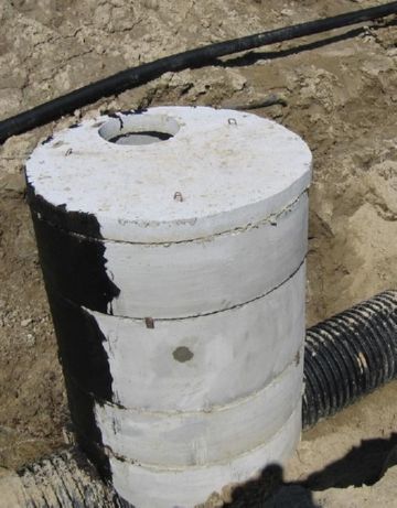
- For regular inspection or viewing - structures are located in places of stop valves and are intended for monitoring and servicing sewer systems.
- Rotary - a kind of manholes. Are arranged at the bending points of the pipeline. The main purpose of such structures is quick access to the bend (elbow) of the pipe in order to clean it from contamination.
- Filtration - special structures devoid of tightness (having a perforated bottom). Serve for accumulation of not strongly polluted runoff waters with their subsequent filtration in soil. It is the ideal solution for draining showers or house drainage systems. At the bottom of the well, a filter of fine gravel and sand is arranged (sometimes the mine is covered with the same material). The thickness of the filter is not less than 40-50 centimeters.
- Gradient - structures designed to dampen or increase the flow rate. Are established in places of sharp deepening of the pipeline or in points of accession to the highway of deep-seated collectors. The design is based on a vertical branch pipe (drop - a part in the form of a straight cross and a knee). The well itself is arranged as a multi-stage structure or has the shape of a classic mine.
- Serving to store water or storage - sealed wells, the liquid from which is pumped out using a pump or flows through a signal pipe into the nearest ravine. To clean such a well, the owners often involve vacuum cleaners. The frequency of cleaning directly depends on the capacity of the well. The more capacious it is, the less often you will have to resort to pumping out the liquid. The average height of the well is two meters.
SNiP standards
The arrangement of any sewer well is regulated by special sanitary and technical standards, displayed in a special document known as SNiP.
This document requires some preliminary work.
Necessary:
- determine the location of the well and make markings on the ground;
- uproot all trees and shrubs that interfere with construction;
- equip the construction site - provide free access for equipment;
- draw up a plan (scheme) and coordinate it with neighbors and the city water utility.
Construction works also have strict regulations and include: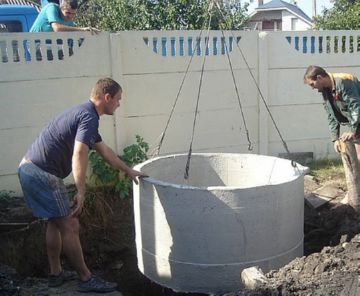
- preparation of a pit (pit);
- backfilling the bottom with rubble and sand;
- carrying out a complete waterproofing of the bottom with a concrete solution;
- installation of concrete rings or a plastic tank;
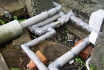
- laying pipes;
- sealing all pipes with cement mortar or bitumen (for concrete structures, holes are sealed around the connected pipes);
- functionality check (testing for the possibility of leakage);
- backfilling the well outside (fine gravel and soil are used for plastic, clay for concrete);
- additional processing of concrete structures with waterproofing materials.
Basic technical requirements.
It can be used if the geological and hydrogeological conditions of the area are suitable for this, and there is also no danger of contamination of water supply systems and soil. The need to use such structures arises when it is impossible to connect to the central networks of the city.
The device of a sewer well as a septic tank
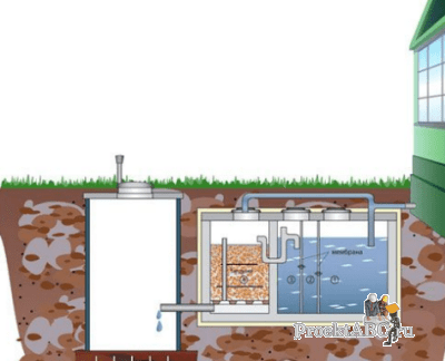
The septic tank provides for the purification of fecal water using the soil principle.Planning for such a system is best done and in progress. Such a sewer system is built as follows: a septic tank is carried out on the site, into which sewage is directed from the house through the yard pipeline. The volume of which is not less than 2.5 m 3, where the water settles, clarifies, and then goes into the soil through the drainage network or drainage well. Sediments from the septic tank are removed twice a year. Wastewater must be settled in a septic tank for three days, therefore, the volume of such a well must be no less than three times the daily volume of effluent.
For example, a septic tank, designed for a capacity of 1 m 3 per day, should have dimensions of 1x1.5 m, the depth of the tank will be 2.5 m. According to the standards, the distance from the house to the septic tank should be from 5 to 20 meters, and the drainage network is laid like this so that wastewater does not erode the foundation and cannot provoke basement flooding.
The pipe for draining water from the septic tank should be laid at a depth of 1.2 m, if freezing of water is possible, then the pipe must be insulated with slag. The pipes themselves can be cast iron or plastic. To the external sewerage system is connected to the outlet from the building -. The device of a sewer well can be carried out from various materials
, including from, concrete, and sometimes from rubble stone. A stone or brick septic tank is plastered from the inside with cement mortar, then ironed, the bottom is made concrete. The septic tank must be well insulated from the outside. If the walls of the septic tank are brick or stone, then a layer of greasy clay from 30 cm thick is laid along the walls and under the bottom, if the walls are concrete, then let the clay be at least 20 cm thick. earth. But a more reliable option is reinforced concrete floors, in which a hatch or door is cut.
It should be noted that it is best to arrange round sewer wells (septic tanks). Walls must be at least 25 cm thick. The pipe through which sewer water will enter the septic tank from the house should be installed 5 cm above the pipe intended for flow into the drainage system. Tees must be installed on the inlet and outlet pipes of the septic tank, through which water will pass. The upper part of the tees is open, and the lower ends, together with their pipes, should be approximately 40 cm below the approximate water level in the septic tank.
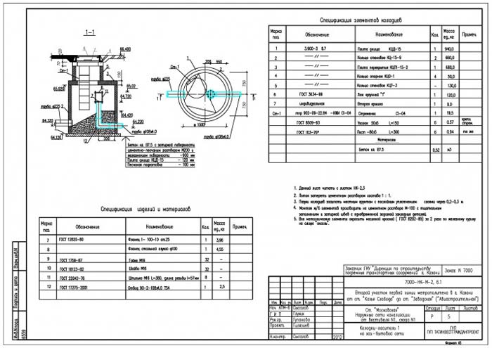
Drop well - drawing in AutoCAD
Immersion of a monolithic well Kl-1 by the lowering method. Work production schemes. Section - Water intake facilities.
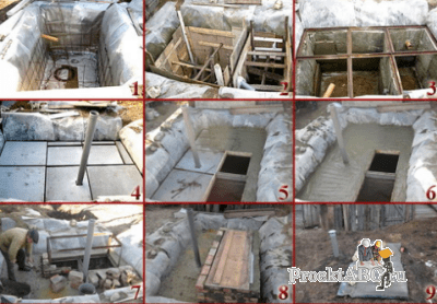
- Stage I (preparatory) of construction:
- 1. Excavation of peaty soils (black peat) to a layer of loam;
- 2. Arrangement of a design embankment for water intake facilities and a pumping station;
- 3. Arrangement of a concrete fore-mine, at the place of technological pits, the fore-mine should be made with the device of expansion joints with separation of blocks with mounting loops;
- II stage of construction:
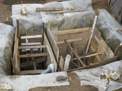
- 1. Excavation along the perimeter of the knife part of the well;
- 2. Installation of formwork, installation of embedded parts, reinforcing meshes and products;
- 3. Backfilling of the sinuses with crushed stone with layer-by-layer compaction;
- 4. Concreting of the knife part of the well to a height of 3.75m.
- III stage of construction:
- 1. Excavation using an excavator equipped with a grab. The excavation should be carried out evenly over the entire area of the well - from the center of the well (I) to its edges (II), while the face surface should have a slope from the knife to the center so that the soil under the weight of the well is evenly squeezed out under the knife bench;
- 2. Formed sinuses to fill with clay solution with a density of at least 1.25t/m³;
- 3. Arrangement of auxiliary scaffolding and scaffolding;
- 4.Installation of formwork, installation of embedded parts, reinforcing meshes and products;
- 5. Concreting of the 1st section of the well to a height of 4.00m.
- III stage of construction:
- 1. Excavation using an excavator equipped with a grab. The excavation should be carried out evenly over the entire area of the well - from the center of the well (I) to its edges (II), while the face surface should have a slope from the knife to the center so that the soil under the weight of the well is evenly squeezed out under the knife bench;
- 2. Formed sinuses to fill with clay solution with a density of at least 1.25t/m³;
- 3. Arrangement of auxiliary scaffolding and scaffolding;
- 4. Installation of formwork, installation of embedded parts, reinforcing meshes and products;
- 5. Concreting of the 1st section of the well to a height of 4.00m.
- IV stage of construction:
- 1. Excavation with the help of an excavator equipped with a grab to the design mark of the immersion of the well;
- 2. At the end of the immersion of the well (draft to the mark of the bottom of the knife part -17.30, mark of the upper edge of the III section -1.150m), plug the slot of the outer jacket with cement mortar grade M50 on sulfate-resistant Portland cement grade M300;
- 3. Anchoring of the well to the foreshaft by means of the device of monolithic stops along the perimeter of the well;
- 4. Cleaning the bottom of the well to the bottom of the knife part.
- V stage of construction:
- 1. The device of continuous flooring at the level of the cut-off of the well;
- 2. Installation of a concrete pipe with a funnel for receiving the concrete mixture;
- 3. Device for leveling concrete pad;
- 4. Pumping ground water from the well;
- 5. Device of auxiliary scaffolding at the lower level of the well;
- 6. Device for leveling screed and waterproofing of the bottom of the well;
- 7. Reinforcement and subsequent concreting of the well bottom slab.
Choosing a place for construction
First of all, it is necessary to find the right place for the construction of the water intake structure and determine its depth. If there are similar structures in neighboring areas, the task is facilitated. To do this, you should talk to your neighbors and ask them for the following information:
- What is the depth of the water intake structure in their area.
- How much water does it give?
- when it was built.
- Features of its use.
When choosing a place for construction, one should be guided by the standard distances from SNiP 30-02-97. According to them, the following minimum distances are allowed between the well and other objects on the site:
- from the foundation of the house to the water intake, the minimum allowable distance is 5 m;
- the minimum distance at which a well can be built from buildings for pets is 4 m;
- to any outbuildings on the site - 1 m;
- trees must be at least 4 m apart;
- at least 1 m retreats from shrubs to the water intake;
- from septic tanks and cesspools to a source of drinking water should be at least 50 m.
According to SNiP, cesspools should not be located above the water intake well.
Well device
Any well for sewerage consists of three structural elements:
- sealed bottom;
- mines of the required depth;
- upper floor, equipped with a round or square hatch.
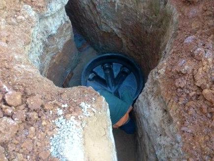
The reinforced concrete structure is built as follows:
- A hole of the required depth is dug with a margin for the free movement of the rings (about 10-20 cm). If the soil is loose and the well is deep (more than 1.5 meters), the recess is made inside the first ring.
- The bottom of the pit is filled with concrete. In the rings, with the help of a perforator, technical holes are punched for the installation of the pipeline. Pipes are fixed with cement mortar and sealant. If it is deep and intended for regular inspection of the sewer, a metal ladder is mounted on its walls for ease of descent.
- From above, the shaft is covered with a concrete slab with a hole for a hatch. A special metal frame is inserted into the hole, and a cover is mounted on top. It can be installed on curtains and equipped with a lock. Or look like a cast iron hatch.
Plastic models include:
- lower tray with branch pipes for connecting pipes;
- shaft made of multilayer plastic;
- adapter pipe of telescopic design;
- cast iron frame and hatch.
All elements are interconnected using rubber seals, ensuring complete tightness of the structure.
.
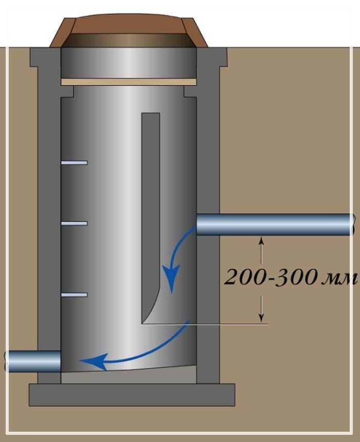
drop well
There are cases when the flow rate should not be lowered, but increased. To do this, a water seal is installed in the design. A chamber is formed that accumulates water, as a result of which it is possible to create the necessary pressure in order to give the required speed to the flow at the outlet of the water valve. All these values are determined in the project calculations.
There are various configurations for the design of differential wells. Sometimes, to regulate the speed of the water flow, a fast flow is organized using a tray laid with a certain slope.
The deeper the absorber well, the stronger the speed reduction effect will be. The pressure of the stream will be extinguished in the water column (pool), into which it strikes from a height. If the pressure needs to be lowered even more, then a retaining wall is built inside the well structure, hitting which the flow loses its speed. Sometimes a sewer pressure absorber is installed after a fast current. It all depends on the specific engineering solution and calculation.
The drawing shows a damper well with a chipper.
This solution is used when you need to further reduce the flow rate:
There are plastic, concrete and brick wells.
In long-distance main pipelines, overflow wells made of concrete are used, but plastic wells are quite suitable for a small private sewer network. Advantages of a plastic damper well:
- light weight;
- facilitated installation process;
- holes for pipelines are provided in the design of the finished product;
- the tightness of the connections of all elements of the system is thought out.
The user opens AutoCAD and uploads the *.arx file to AutoCAD using the appload command. After that, the designer will see an additional toolbar in AutoCAD, in fact it is just one button.
Sequencing
The sequence of actions in this program is very simple, and if you understand the process of designing sewer wells, then you will receive a drawing and specification in just 5-10 minutes of working time.
After pressing the button,
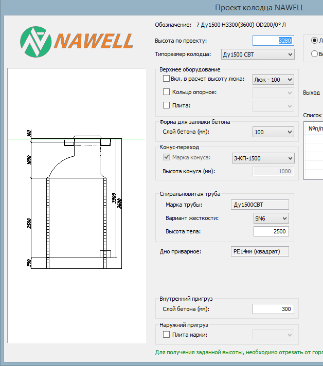
the user gets only one window with various options and a preview window on the left. Despite the simple appearance of the window, the program contains a complex algorithm for selecting the details of the well and calculating its allowable height.

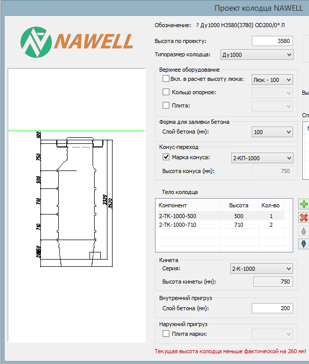
Initial (blank) window when designing a well
In the first step, the user must set the height of the well in millimeters in accordance with the task and select the diameter of the well from four options: D1000 mm, D1500 mm, D1000 mm SVT, D1500 mm SVT. Depending on the selected diameter, the type of well and the entered height, the program automatically creates a well! All that remains for the user is to correct the values and set additional settings.
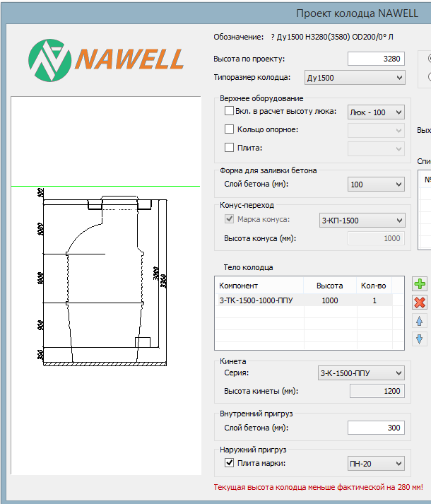
Automatically built well D1500 SVT Automatically built well D1000
In the preview window, the user sees the future drawing - the result of automatic assembly. At the bottom of the window is a program message about whether the height has exceeded the required one or not. Of course, the designer must additionally set special parameters for the well, which depend on the environment. These are parameters such as the presence of support rings, the amount of concrete for the load, additional stabilizing plates, etc. Each newly set parameter affects the height of the well.
In the figure below, the user has added a hatch 100 mm thick, three support rings, the upper slab P-20, the thickness of the concrete layer, the internal weight of the well 500 mm, etc. And after these actions, the designer receives the required height of the well, which satisfies the task.
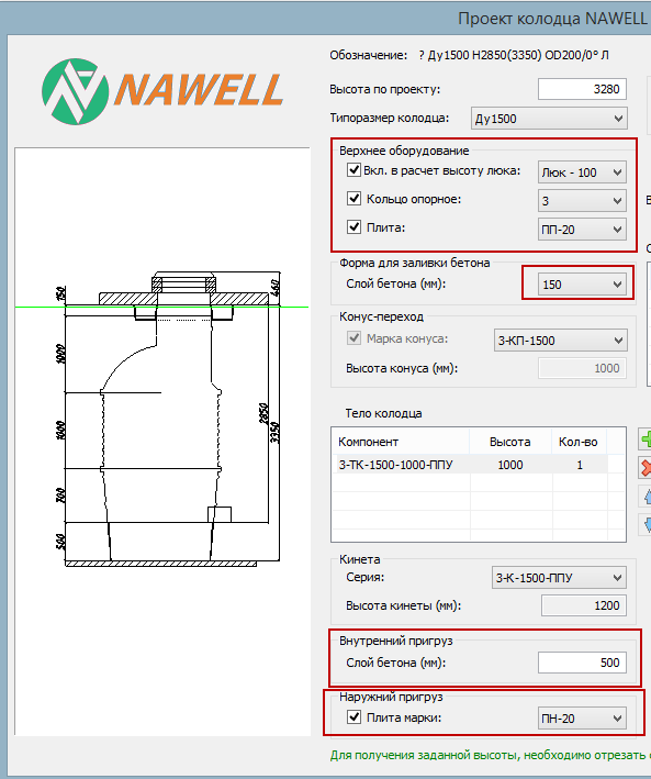
Automatically built well D1500 D1500 well with advanced parameters
Inlet and outlet pipes
Second step
is the creation of inlet pipes and an exhaust pipe. The outlet pipe can only be single, and there can be multiple inlet pipes. The user must select the type and diameter of the outlet pipe (OUTLET) and create inlet pipes from the list provided by the program. The program also automatically finds the appropriate tray for the inlet pipes and the outlet pipe.

Drawing and specification
When the user is sure that he has finished designing the well, he must click the "Next" button. After clicking, the designer automatically receives a drawing and specification based on the company's template.
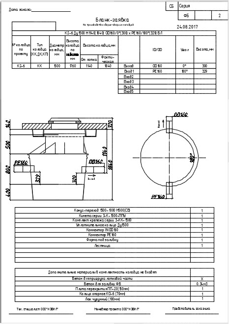

Drawing example after clicking Next


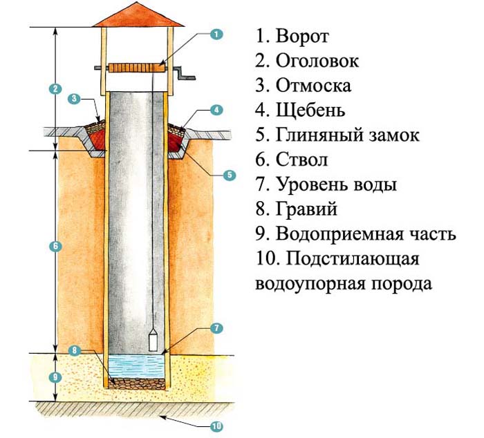
Shaft well device
In the design of such wells, three main parts can be distinguished:
- water intake
- This is the lower part of the structure. It is used to filter and collect water. - Trunk
- this is the underground part of the shaft of the structure, located above the water intake. It reliably protects the structure from collapse and preserves the quality of drinking water, without letting the perch into the water intake. - headroom
- this is the part of the structure located above the ground. The main purpose of this part is to protect the water intake from dust, debris, surface sedimentary water and freeze protection during the cold season. The head is necessarily protected by a roof.
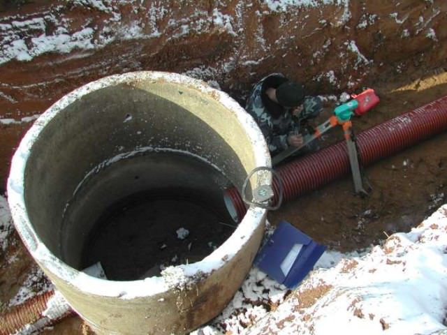
Installation of a concrete well
The device of a sewer well made of concrete rings and bricks has practically no differences in terms of the order of installation work.
The following work is being carried out:
- Digging a pit.
- Creation of the foundation (a poured base can be performed or a ready-made concrete slab can be used). The thickness of the base is about 100 mm, the recommended brand of concrete is M50.
- Construction of the tray (carried out taking into account the number of supplies, the angles of the connection of communications, the presence of turns and other features). M100 concrete reinforced with metal mesh is used.
- Sealing (with concrete and bitumen in series) the places where pipes enter the well.
- Installation of rings with fixation with cement mortar, construction of a brick structure (after full curing of the tray concrete).
- Bituminous waterproofing of the inner surface of the walls (when building from rings, it can be done before installation).
- Seam waterproofing (for ring structures).
- Tray finishing (cement plaster and ironing technology are used).
- Arrangement of clay locks at the junction of pipes with the tank (height - 600 mm, width - 300 mm).
- Testing the structure, keeping the tank filled with water for a day (temporary plugs are installed on the pipes at this time) to detect leaks. A reinforced concrete sewer well is considered serviceable if there are no visually noticeable leaks.
- Backfilling the well with earth and tamping the soil.
- from concrete along the perimeter of the neck 1.5 m wide.
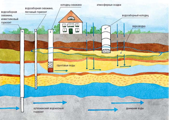
In the absence of a central water supply on the site, underground horizons can become the only source of drinking and domestic water. To get to this water, it is necessary to arrange a water well. If you follow the technology of its manufacture, you can get a durable and easy-to-use source of clean drinking water. From such a well it is easy to supply water to a house or cottage. However, when choosing a site for construction and installation of a structure, it is necessary to strictly follow the rules of SNiP 2.04.02-84.
There are two types of water wells:
- tubular;
- mine.
The first type is commonly called a column. Usually they were installed on the streets of villages. A hand pump is used to extract water from the depth in such wells. These wells are installed in places of shallow occurrence of aquifers. Its installation is very fast.But for the construction of a tubular well, drilling equipment will be needed, because they do not dig a hole, but drill it.
A shaft well is the most affordable option for self-assembly. It is dug with a shovel, and the walls are strengthened. This is a traditional well for country houses and cottages. Depending on the material of manufacture, several types of mine water wells are distinguished:
- plastic;
- reinforced concrete;
- brick or stone;
- wood.
Reinforced concrete wells are the most popular. They are durable (can last up to 50 years). Their depth reaches 15-20 m. However, the installation of such a water intake device will require a lot of labor. First of all, a lot of effort will be spent on digging a deep hole. At the same time, its diameter must be larger than the size of the rings in order to perform a sand and gravel backfill from the outside. And to lower the concrete rings, you will have to order a construction crane. At the bottom of such a well, a filter is arranged from a sand and gravel cushion 300-400 mm high.
Recently, more and more often the owners of private houses choose plastic water wells. Their main advantage is that it is a one-piece design due to the high tightness of all joints and seams. The dimensions of such structures can be any, depending on the requirements. They are no less durable than reinforced concrete devices, and can also last up to 50 years. Their additional advantage is the speed of installation without the use of construction equipment.
Wooden and brick water intake structures are a thing of the past. Now they are practically not made due to the laboriousness and duration of the construction process. In addition, these structures do not meet the requirements of SNiP, because silt and dirt quickly settle on the brick and wooden walls of such water wells, which reduces the quality of drinking water.
Types of sewer wells
A structure of this kind has its own purpose and method of construction. Sewer tanks differ in a number of ways.
By functional purpose
There are several types of wells:
-
Cumulative.
This is a more modern and environmentally friendly version of the waste pit. It carries out fractionation of effluents and sewage. Liquid and light particles are sent to the filter, and heavy particles sink to the bottom of the storage tank. The volume of the structure is 2-50 thousand liters and depends on the amount of water used. It must be installed at the lowest point of the site, which ensures the correct angle of inclination of the sewer pipes. -
Filtering.
The facility is designed to discharge wastewater into the soil. There is no bottom in the design of the well. The installation of filter collectors is allowed only on sandy and sandy-clay soils. As a rule, wells are made from. Sand, crushed stone and special materials can serve as a filter. -
Lookout.
It is used for periodic inspection and convenient cleaning of the drainage system in small areas where the direction, slope or diameter of pipes changes, in connection areas. Unlike other types of treatment facilities, presented in the form of a pipe or a collection tank, the inspection tank is an open container. It is mounted in a straight line with a step of 15 meters, while the initial well is placed at a distance from the house no closer than 3 meters and no further than 12 meters. -
Turning.
The structure is intended for areas with an extensive drainage pipeline, as well as in cases where the angle of rotation on the pipeline exceeds 90 degrees. This is due to the lack of the possibility of arranging a continuous straight section from a residential building to a storage septic tank. Rotary collectors must be erected at each bend of the laid pipe. This design can be used as a viewing septic tank, which makes it quite easy to clean a certain section of the pipeline through it. -
Variable.
Used in areas with a large elevation difference. In this case, the inlet pipe is placed much higher than the outlet. The design of the septic tank has a descent, which is a vertical pipe entering the well, which is connected to the inlet. The descent is attached to the wall of the tank by means of clamps. The length of this element depends on the difference in the section. On the reverse side of the lowering, a 45-degree outlet is installed.
According to the materials used
Collectors are made from various materials:
-
Reinforced concrete.
The structures are distinguished by their strength, resistance to the negative effects of chemical compounds, and sufficient ease of installation. In addition, they have a large weight and different diameters of the rings. Products are used for the device of septic tanks of the filtering, accumulative and viewing type. Suitable for installation in any type of soil. -
Brick.
For the construction of the collector, clay waterproof bricks are often used. Bricks can be used to build square, rectangular or round structures. -
Plastic.
Polyethylene structures are characterized by high strength, tightness, wear resistance, as well as ease of installation and relatively low cost. Are applied to the device of rotary, differential and viewing septic tanks.
Installation of a plastic well
The use of ready-made plastic structures, complete with fittings, will not only save time, but will also make it possible to independently perform the installation, even in the absence of experience and training.
It is only important to strictly comply with the requirements regarding the location of structures and the choice of their size, which are determined by the totality of system parameters (pipe diameter, straightness or the presence of line turns, laying depth, etc.). The rest of the installation is carried out in several steps:
- digging a pit,
- foundation construction (sand and gravel cushion, flood base),
- installation of the structure (and its anchoring if necessary),
- connection of the well to the system.