The first method is classic, see Figure 8
1. Outdoor air treatment processes:
- heating of outside air in the heater of the 1st heating;
- humidification according to the adiabatic cycle;
- heating in the heater of the 2nd heating.
2. From a point with outdoor air parameters - (•) H we draw a line of constant moisture content - dH = const.
This line characterizes the process of heating the outside air in the heater of the 1st heating. The final parameters of the outdoor air after heating will be determined in point 8.
3. From the point with the supply air parameters - (•) P we draw a line of constant moisture content dP = const until it intersects with the line of relative humidity φ = 90% (this relative humidity is stably provided by the irrigation chamber with adiabatic humidification).
We get the point - (•) O with the parameters of humidified and cooled supply air.
4. Through the point - (•) O we draw the line of the isotherm - tO = const up to the intersection with the temperature scale.
The temperature value at the point - (•) O is close to 0°C. Therefore, mist may form in the spray booth.
5. Therefore, in the zone of optimal parameters of indoor air in the room, it is necessary to choose another point of indoor air - (•) B1 with the same temperature - tIN 1 = 22°С, but with higher relative humidity - φIN 1 = 55%.
In our case, the point is (•) B1 was taken with the highest relative humidity from the zone of optimal parameters. If necessary, it is possible to accept an intermediate relative humidity from the zone of optimal parameters.
6. Similar to point 3. From a point with supply air parameters - (•) P1 draw a line of constant moisture content dP1 = const to the intersection with the line of relative humidity φ = 90% .
We get a point - (•) O1 with parameters of humidified and cooled supply air.
7. Through a point - (•) O1 draw an isotherm line - tO1 = const up to the intersection with the temperature scale and read the numerical value of the temperature of humidified and cooled air.
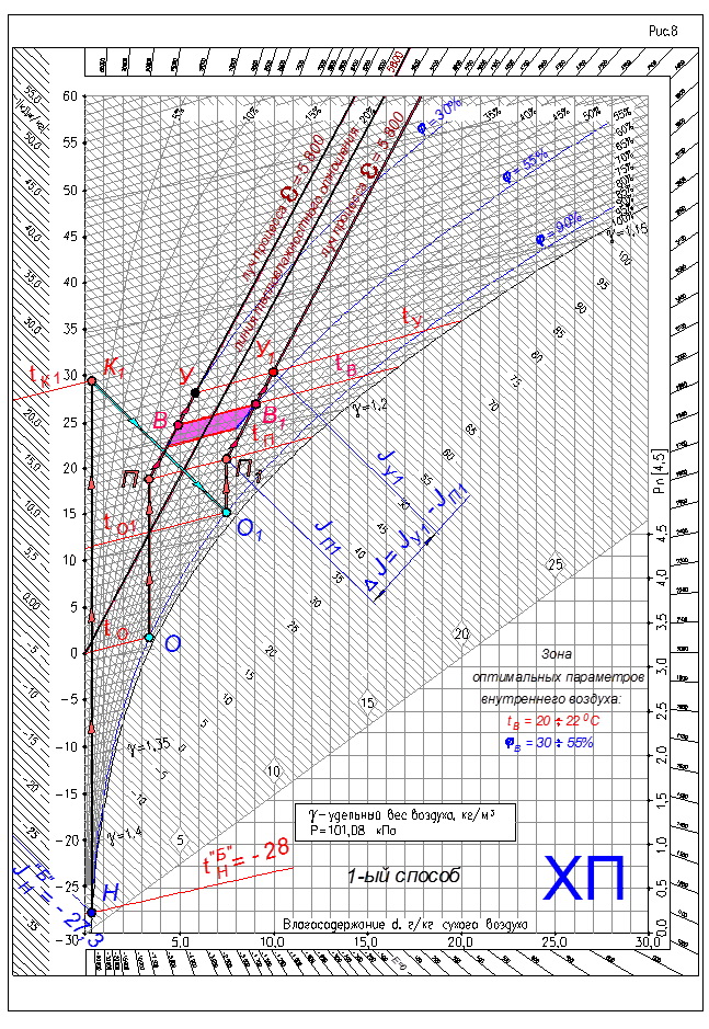
Important note!
The minimum value of the final air temperature for adiabatic humidification should be within 5 ÷ 7°C.
8. From a point with supply air parameters - (•) P1 we draw a line of constant heat content - JP1 = const to the intersection with the line of constant moisture content of the outside air - point (•) H - dH = const.
We get a point - (•) K1 with the parameters of the heated outside air in the heater of the 1st heating.
9. Outdoor air treatment processes on the J-d diagram will be represented by the following lines:
- NK line1 - the process of heating the supply air in the heater of the 1st heating;
- line K1O1 – the process of humidifying and cooling the heated air in the irrigation chamber;
- line O1P1 — the process of heating humidified and cooled supply air in the 2nd heating heater.
10. Treated outdoor supply air with parameters at the point - (•) P1 enters the room and assimilates excess heat and moisture along the process ray - line P1V1. Due to the increase in air temperature along the height of the room - grad t. Air parameters change. The process of changing parameters occurs along the process beam to the point of outgoing air - (•)1.
11. The required amount of supply air to assimilate excess heat and moisture in the room is determined by the formula
12. The required amount of heat to heat the outside air in the 1st preheater
Q1 = GΔJ(JK1 —JH) = GΔJ(tK1 — tH), kJ/h
13. The required amount of moisture to humidify the supply air in the irrigation chamber
W=GΔJ(dO1 - dK1), g/h
14. The required amount of heat to heat the humidified and cooled supply air in the 2nd preheater
Q2 = GΔJ(JP1 —JO1) = GΔJ x C(tP1 — tO1), kJ/h
The value of the specific heat capacity of air C is taken:
C = 1.005 kJ/(kg × °C).
To obtain the thermal power of the heaters of the 1st and 2nd heating in kW, it is necessary to measure Q1 and Q2 in units of kJ/h divided by 3600.
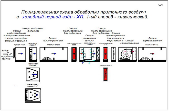
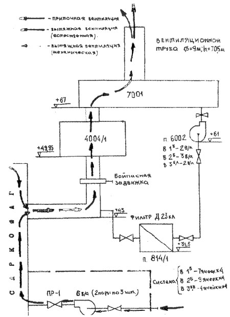
Schematic diagram of the treatment of supply air in the cold season - HP, for the 1st method - the classic, see Figure 9.
Video on ventilation calculation
Useful information on the principles of operation of the ventilation system is contained in this video:
Together with the exhaust air, heat also leaves the home. Here, the calculations of heat losses associated with the operation of the ventilation system are clearly demonstrated:
The correct calculation of ventilation is the basis for its successful functioning and the guarantee of a favorable microclimate in a house or apartment. Knowing the basic parameters on which such calculations are based will allow not only to correctly design the ventilation system during construction, but also to correct its condition if circumstances change.
In accordance with the sanitary norms and rules for the organization of premises, both domestic and industrial, in force on the territory of the Russian Federation, optimal microclimate parameters must be ensured. Ventilation rates regulate such indicators as air temperature, relative humidity, air velocity in the room and the intensity of thermal radiation. One of the means to ensure optimal microclimate characteristics is ventilation. At present, organizing an air exchange system “by eye” or “approximately” will be fundamentally wrong and even harmful to health. When arranging the ventilation system, the calculation is the key to its proper functioning.
In residential buildings and apartments, air exchange is often provided by natural ventilation. Such ventilation can be implemented in two ways - ductless and ducted. In the first case, air exchange is carried out during the ventilation of the room and the natural infiltration of air masses through the cracks of doors and windows, and the pores of the walls. In this case, it is impossible to calculate the ventilation of the room, this method is called unorganized, has low efficiency and is accompanied by significant heat losses.
The second method is to place air ducts in the walls and ceilings of the channels through which air is exchanged. In most apartment buildings built in the 1930-1980s, an exhaust duct ventilation system with natural induction is equipped. The calculation of exhaust ventilation is reduced to determining the geometric parameters of air ducts that would provide access to the required amount of air in accordance with GOST 30494-96 “Residential and public buildings. Indoor microclimate parameters.
In most public spaces and industrial buildings, only the organization of ventilation with mechanical induction of air movement can provide sufficient air exchange.
The calculation of industrial ventilation can only be entrusted to a qualified specialist. The ventilation design engineer will make the necessary calculations, draw up a project and approve it in the relevant organizations. They will also draw up ventilation documentation.
The design of ventilation and air conditioning is focused on the task set by the client. In order to select equipment for an air exchange system with optimal characteristics that meets the set conditions, the following calculations are performed using specialized computer programs.
Examples of air exchange volume calculations
To make a calculation for the ventilation system by multiplicity, first you need to make a list of all the rooms in the house, write down their area and ceiling height. For example, a hypothetical house has the following rooms:
- Bedroom - 27 sq.m.;
- Living room - 38 sq.m.;
- Cabinet - 18 sq.m.;
- Children's room - 12 sq.m.;
- Kitchen - 20 sq.m.;
- Bathroom - 3 sq.m.;
- Bathroom - 4 sq.m.;
- Corridor - 8 sq.m.
Considering that the ceiling height in all rooms is three meters, we calculate the corresponding air volumes:
- Bedroom - 81 cubic meters;
- Living room - 114 cubic meters;
- Cabinet - 54 cubic meters;
- Children's room - 36 cubic meters;
- Kitchen - 60 cubic meters;
- Bathroom - 9 cubic meters;
- Bathroom - 12 cubic meters;
- Corridor - 24 cubic meters.
Now, using the table above, you need to calculate the ventilation of the room, taking into account the air exchange rate, increasing each indicator to a value that is a multiple of five:
- Bedroom - 81 cubic meters * 1 = 85 cubic meters;
- Living room - 38 sq.m. * 3 = 115 cubic meters;
- Cabinet - 54 cubic meters. * 1 = 55 cubic meters;
- Children's - 36 cubic meters. * 1 = 40 cubic meters;
- Kitchen - 60 cubic meters. - not less than 90 cubic meters;
- Bathroom - 9 cubic meters. not less than 50 cubic meters;
- Bathroom - 12 cubic meters. not less than 25 cubic meters
There is no information about the standards for the corridor in the table, so the data for this small room is not taken into account in the calculation. For the hotel, a calculation was made for the area, taking into account the standard of three cubic meters. meters for every square meter. Now you need to separately summarize the information for the rooms in which air is supplied, and separately for the rooms where exhaust ventilation devices are installed.
Total: 295 cubic meters per hour
Kitchen - 60 cubic meters. - not less than 90 cubic meters / h;
Total: 165 m3/h
Now you should compare the received amounts. Obviously, the required inflow exceeds the exhaust by 130 m3/h (295 m3/h-165 m3/h). To eliminate this difference, it is necessary to increase the volume of air exchange through the hood, for example, by increasing the indicators in the kitchen. After editing, the calculation results will look like this:
The volume of air exchange by inflow:
- Bedroom - 81 cubic meters * 1 = 85 m3/h;
- Living room - 38 sq.m. * 3 = 115 cubic meters / h;
- Cabinet - 54 cubic meters. * 1 = 55 m3/h;
- Children's - 36 cubic meters. * 1 = 40 m3/h;
Total: 295 cubic meters per hour
Exhaust air exchange volume:
- Kitchen - 60 cubic meters. - 220 cubic meters / h;
- Bathroom - 9 cubic meters. not less than 50 cubic meters / h;
- Bathroom - 12 cubic meters. not less than 25 cubic meters / h.
Total: 295 m3/h
The inflow and exhaust volumes are equal, which meets the requirements for calculating air exchange by multiplicity.
The calculation of air exchange in accordance with sanitary standards is much easier to perform. Let us assume that two people live permanently in the house discussed above, and two more people stay in the room irregularly. The calculation is performed separately for each room in accordance with the norm of 60 cubic meters per person for permanent residents and 20 cubic meters per hour for temporary visitors:
- Bedroom - 2 people * 60 = 120 cubic meters / hour;
- Cabinet - 1 person. * 60 \u003d 60 cubic meters / hour;
- Living room 2 people * 60 + 2 people * 20 = 160 cubic meters per hour;
- Children's 1 pers. * 60 \u003d 60 cubic meters / hour.
Total inflow - 400 cubic meters per hour.
There are no strict rules for the number of permanent and temporary residents of the house, these figures are determined based on the real situation and common sense. The hood is calculated according to the standards set out in the table above, and is increased to the total inflow rate:
- Kitchen - 60 cubic meters. - 300 cubic meters / h;
- Bathroom - 9 cubic meters. not less than 50 cubic meters / h;
Total for the hood: 400 cubic meters / h.
Increased air exchange for the kitchen and bathroom. Insufficient exhaust volume can be divided between all rooms in which exhaust ventilation is installed, or this indicator can be increased only for one room, as was done when calculating by multiplicity.
In accordance with sanitary standards, air exchange is calculated in a similar way. Let's say the area of the house is 130 sq.m. Then the air exchange through the inflow should be 130 sq.m * 3 cubic meters / hour = 390 cubic meters / hour. It remains to distribute this volume to the rooms according to the hood, for example, in this way:
- Kitchen - 60 cubic meters. - 290 cubic meters / h;
- Bathroom - 9 cubic meters. not less than 50 cubic meters / h;
- Bathroom - 12 cubic meters. not less than 50 cubic meters / h.
Total for the hood: 390 cubic meters / h.
Air exchange balance is one of the main indicators in the design of ventilation systems. Further calculations are performed based on this information.
Second option.
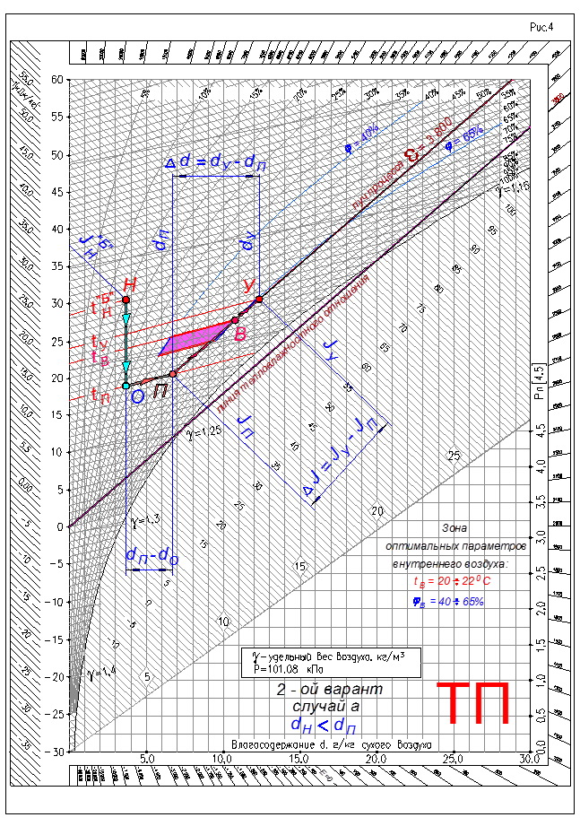
(See Figure 4).
Absolute air humidity or moisture content of outdoor air - dH"B", less moisture content of the supply air - dP
dH"B" P g/kg.
1. In this case, it is necessary to cool the outside supply air - (•) H on the J-d diagram, to the temperature of the supply air.
The process of air cooling in a surface air cooler on the J-d diagram will be represented by a straight line BUT.The process will occur with a decrease in heat content - enthalpy, a decrease in temperature and an increase in the relative humidity of the external supply air. At the same time, the moisture content of the air remains unchanged.
2. In order to get from the point - (•) O, with the parameters of cooled air to the point - (•) P, with the parameters of the supply air, it is necessary to humidify the air with steam.
At the same time, the air temperature remains unchanged - t = const, and the process on the J-d diagram will be depicted by a straight line - an isotherm.
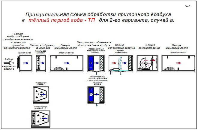
Schematic diagram of the supply air treatment in the warm season - TP, for the 2nd option, case a, see Figure 5.
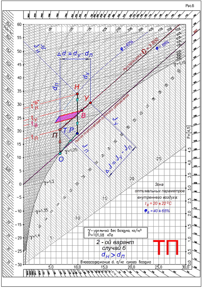
(See Figure 6).
Absolute air humidity or moisture content of outdoor air - dH"B", more moisture content in the supply air - dP
dH"B" > dP g/kg.
1. In this case, it is necessary to “deeply” cool the supply air. That is, the process of air cooling on the J - d diagram will initially be depicted by a straight line with a constant moisture content - dH = const, drawn from a point with outdoor air parameters - (•) H, to the intersection with the line of relative humidity - φ = 100%. The resulting point is called - dew point - T.R. outside air.
2. Further, the cooling process from the dew point will go along the line of relative humidity φ = 100% to the final cooling point - (•) O. The numerical value of the air moisture content from the point (•) O is equal to the numerical value of the air moisture content at the inflow point - (•) P .
3. Next, you need to heat the air from the point - (•) O, to the point of supply air - (•) P. The process of heating the air will occur with a constant moisture content.
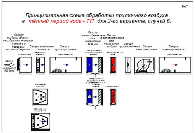
Schematic diagram of the treatment of supply air in the warm season - TP, for the 2nd option, case b, see Figure 7.
Determining the power of the heater
Ventilation design standards suggest that during the cold season, the air entering the room must warm up to at least +18 degrees Celsius. The supply and exhaust ventilation uses a heater to heat the air. The criterion for choosing a heater is its power, which depends on the ventilation performance, the temperature at the outlet of the duct (usually taken +18 degrees) and the lowest air temperature in the cold season (for central Russia -26 degrees).
Various heater models can be connected to a network with 3 or 2 phase power supply. In residential premises, a 2-phase network is usually used, and for industrial buildings it is recommended to use a 3-phase network, since in this case the value of the working current is less. A 3-phase network is used in cases where the heater power exceeds 5 kW. For residential premises, heaters with a capacity of 1 to 5 kW are used, and for public and industrial premises, respectively, more power is required. When calculating the ventilation of heating, the power of the heater must be sufficient to provide air heating to at least +44 degrees.
Types of air exchange used in industrial enterprises
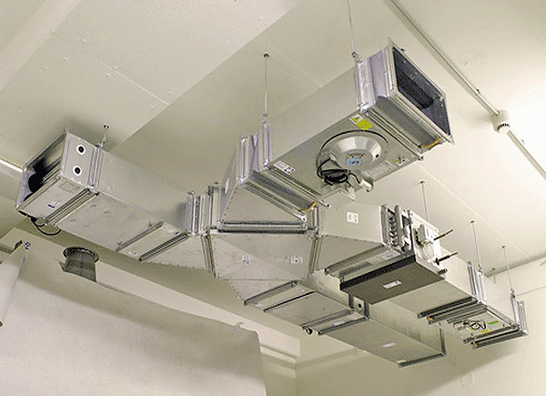
Industrial ventilation systems
Regardless of the type of production, quite high requirements are placed on air quality in any enterprise. There are standards for the content of various particles. In order to fully comply with the requirements of sanitary standards, various types of ventilation systems have been developed. The air quality depends on the type of air exchange used. Currently, the following types of ventilation are used in production:
- aeration, that is, general ventilation with a natural source. It regulates the air exchange throughout the room. It is used only in large industrial premises, for example, in workshops without heating. This is the oldest type of ventilation, it is currently used less and less, as it does not cope well with air pollution and is not able to regulate the temperature;
- local extract, it is used in industries where there are local sources of emission of harmful, polluting and toxic substances. It is installed in the immediate vicinity of the release points;
- supply and exhaust ventilation with artificial induction, used to regulate air exchange over large areas, in workshops, in various rooms.
Calculation of the duct network
For rooms where duct ventilation will be installed, the calculation of air ducts consists in determining the required operating pressure of the fan, taking into account losses, air flow speed and permissible noise level.
The air flow pressure is created by the fan and is determined by its technical characteristics. This value depends on the geometric parameters of the duct (round or rectangular section), its length, the number of network turns, transitions, distributors. The greater the performance that supply ventilation provides, and, accordingly, the operating pressure, the greater the air velocity in the duct. However, as the airflow speed increases, the noise level increases. It is possible to reduce the speed and noise level by using air ducts of a larger diameter, which is not always possible in residential premises. For a person to feel comfortable, the air speed in the room should be in the range from 2.5 to 4 m / s and the noise level should be 25 dB.
You can make an example of calculating ventilation only if you have the parameters of the room and the terms of reference. Specialized firms, which often also carry out the design and installation of ventilation, can provide assistance in performing preliminary calculations, give qualified advice, and draw up the relevant documents.
Before purchasing equipment, it is necessary to calculate and design ventilation systems. When selecting equipment for the ventilation system, it is worth considering the following characteristics
- Air efficiency and performance;
- Heater power;
- Working pressure of the fan;
- Air flow rate and duct diameter;
- Maximum noise figure;
air performance.
The calculation and drafting of the ventilation system must begin with the calculation of the required air productivity (cubic meter / hour). In order to correctly calculate the power, you need a detailed plan of the building or room for each floor with an explication indicating the type of room and its purpose, as well as the area. They start counting by measuring the required air exchange rate, which shows the number of times the air is changed in the room per hour. So for a room with a total area of 100 m2, the height of the ceilings in which is 3 m (volume 300 m3), a single air exchange is 300 cubic meters per hour. The required air exchange rate is determined by the type of use of the premises (residential, administrative, industrial), the number of people staying there, the power of heating equipment and other heat-generating devices, and is indicated in SNiP. Usually, a single air exchange is enough for residential premises, two or three air exchanges are optimal for office buildings.
1. We consider the frequency of air exchange:
L=n* S*H, values n - air exchange rate: for domestic premises n = 1, for administrative premises n = 2.5; S - total area, square meters; H - ceiling height, meters;
2. Calculation of air exchange by the number of people: L = N * L norms, values L - the required performance of the supply ventilation system, cubic meters per hour; N - the number of people in the room; L norms - the amount of air consumption by one person: a) Minimum physical activity - 20 m3/h; b) Average - 40 m3/h; c) Intensive — 60 m3/h.
Having calculated the required air exchange, we begin the selection of ventilation equipment of suitable capacity. It must be remembered that due to the resistance of the duct network, work efficiency is reduced. The relationship between performance and total pressure is easy to recognize from the ventilation characteristics indicated in the technical description.For example: a 30 m long duct network with a single ventilation grill produces a pressure reduction of approximately 200 Pa.
- For residential premises - from 100 to 500 m3 / h;
- For private houses and cottages - from 1000 to 2000 m3/h;
- For administrative premises - from 1000 to 10000 m3 / h.
Heater power.
The heater, if necessary, heats up the outside cold air in the supply ventilation system. The power of the heater is calculated according to such data as: ventilation performance, required indoor air temperature and minimum outdoor air temperature. The second and third indicators are set by SNiP. The air temperature in the room should not fall below +18 °C. The lowest air temperature for the Moscow region is considered to be -26 °C. Therefore, the heater at maximum power should heat the air flow by 44 °C. Frosts in the Moscow region, as a rule, are rare and pass quickly; in supply ventilation systems, it is possible to install heaters with less than calculated power. The system must have a fan speed controller.
When calculating the performance of the heater, it is important to consider: 1. Single-phase or three-phase electricity voltage (220 V) or (380 V)
If the power rating of the heater is more than 5 kW, a three-phase power supply is required.
2. Maximum power consumption. The electricity consumed by the heater can be calculated by the formula: I \u003d P / U, in which I is the maximum electricity consumption, A; U is the mains voltage (220 V - one phase, 660 V - three phases);
The temperature to which a heater of a given capacity can heat the supply air flow can be calculated using the formula: W;L is the power of the ventilation system, m3/h.
Standard heater power indicators are 1 - 5 kW for residential premises, from 5 to 50 kW for administrative ones. If it is impossible to operate an electric heater, it is optimal to install a water heater that uses water from a central or individual heating system as a heat carrier.
Warm period of the year TP.
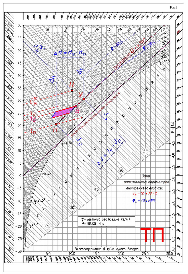
1. When air conditioning in the warm period of the year - TP, the optimal parameters of indoor air in the working area of the premises are initially taken:
tV = 20 ÷ 22ºC; φV = 40 ÷ 65%.
2. The boundaries of the optimal parameters during conditioning are plotted on the J-d diagram (see Figure 1).
3. To achieve optimal parameters of indoor air in the working area of the premises during the warm period of the year - TP, cooling of the outdoor supply air is required.
4. In the presence of heat excesses in the room during the warm period of the year - TP, and also considering that the supply air is cooled, it is advisable to choose the highest temperature from the zone of optimal parameters
tV = 22ºC
and the highest relative humidity of the internal air in the working area of the room
φV = 65%.
We get on the J-d diagram the point of internal air - (•) B.
5. We draw up the heat balance of the room for the warm period of the year - TP:
- sensible heat ∑QTPI AM
- by total heat ∑QTPP
6. Calculate the flow of moisture into the room
∑W
7. We determine the thermal tension of the room according to the formula:
where: V is the volume of the room, m3.
8. Based on the magnitude of the thermal stress, we find the gradient of temperature rise along the height of the room.
The air temperature gradient along the height of the premises of public and civil buildings.
| Thermal tension of the room QI AM/Vpom. | gradt, °C | |
|---|---|---|
| kJ/m3 | W/m3 | |
| Over 80 | Over 23 | 0,8 ÷ 1,5 |
| 40 ÷ 80 | 10 ÷ 23 | 0,3 ÷ 1,2 |
| Less than 40 | Less than 10 | 0 ÷ 0,5 |
and calculate the temperature of the exhaust air
tY = tB + grad t(H - hr.z.), ºС
where: H is the height of the room, m; hr.z. — height of the working area, m.
9. For assimilation, the supply air temperature is tP we accept 4 ÷ 5ºС below the temperature of the internal air - tV, in the working area of the room.
10.We determine the numerical value of the heat-humidity ratio
11. On the J-d diagram, we connect the 0.0 ° C point of the temperature scale with a straight line with the numerical value of the heat-humidity ratio (for our example, we take the numerical value of the heat-humidity ratio as 3,800).
12. On the J-d diagram, we draw the supply isotherm - tP, with numerical value
tP = tV - 5, ° С.
13. On the J-d diagram, we draw an isotherm of the outgoing air with the numerical value of the outgoing air - tAtfound in point 8.
14. Through the point of internal air - (•) B, we draw a line that is parallel to the line of heat-humidity ratio.
15. The intersection of this line, which will be called the ray of the process
with isotherms of supply and exhaust air - tP and tAt determines on the J-d diagram the point of supply air - (•) P and the point of outgoing air - (•) U.
16. Determine the air exchange by total heat
and air exchange for the assimilation of excess moisture
The principle of calculation when selecting a PES with a heat exchanger
In both cases, we expect approximately the same calculations. At the "head of the table" is the performance or air consumption. Productivity - the amount of air passed per unit of time. Measured in cube. m/hour. To select this indicator, we calculate the volume of air in ventilated rooms and add 20% (for the resistance of filters, grilles). The resistance of the built-in heat exchanger is already taken into account in the unit's passport data.

Attention! When calculating independently, rounding and tolerances should be done with an increase towards the margin (power, productivity, volume). Consider the example of a country house with ceilings of 2.4 m, 2 bedrooms (12 m 2 each), a living room (20 m 2), a bathroom (6 m 2) and a kitchen (12 m 2) are served
Consider the example of a country house with ceilings of 2.4 m, 2 bedrooms (12 m 2 each), a living room (20 m 2), a bathroom (6 m 2) and a kitchen (12 m 2) are served.
Total air volume: (2 x 12 + 20 + 6 + 12) x 2.4 = 148.8
, accept 150 m
3 .
Note.
The choice of a more powerful installation is justified if it is possible to increase the area of the premises and to increase the resource of the unit.
Air handling units with built-in heat exchangers
| Indicator | PES model | |||||
| VUT 200 G mini | VUT 400 EH EC ECO | Dantex DV-350E | DAIKIN VAM350FA | |||
| Manufacturer | VENTS, Ukraine | VENTS, Ukraine | VENTS, Ukraine | Dantex, England | Daikin, Japan | Daitherm, Denmark |
| Productivity, m 3 / hour | 100 | 200 | 450 | 350 | 350 | 520 |
| 86 | 116 | 300 | 140 | 200 | 350 | |
| Heat exchanger type | Plates, paper | Plates, aluminum | Countercurrent, polystyrene | Countercurrent, polymer | Counterflow, aluminum | Plates, bimetal |
| 68 | 85 | 98 | 88 | 92 | 95 | |
| Note | Coarse filters | G4 filters, heating optional | Filters G4, F7, heater | 3 operating modes, filters | Fully automatic, replaceable filters | Full automatic, room version |
| price, rub. | 13800 | 16500 | 20800 | 32200 | 61700 | 85600 |

For those who fundamentally do everything with their own hands, the system performance calculations will concern the fans built into the channels. Their performance should already be calculated during the design (calculation) of channels, depending on the volume of air. To select the appropriate heat exchanger, we calculate the total capacity of the fans operating for the inflow to the heat exchanger, and subtract 25% (for system resistance, variable cross section and synchronous operation). One duct fan must also be installed at each inlet and outlet of the heat exchanger.
For our example:
Factory heat exchangers
Question
: What do the numbers 40-20 mean in the marking of factory recuperators?
Answer:
Dimensions of inlet and outlet channels in millimeters. 40-20 - the minimum dimensions of factory heat exchangers.
When installing such a device in a cold place, for example, in the attic, remember that it and the air ducts should be insulated.
Another type of recuperators is autonomous channel heat exchangers. They are also called ventilators. These devices serve only one room and belong to the so-called decentralized ventilation system. They do not require calculations, it is enough to choose a model for the volume of the room.

Air ventilators
| Indicator | Model of duct ventilator | ||||
| PRANA-150 | VENTS TWINFRESH R-50/RA-50 | O'ERRE TEMPERO | MARLEY MENV 180 | SIEGENIA AEROLIFE | |
| Manufacturer | Ukraine | Ukraine | Italy | Germany | Germany |
| Productivity, m 3 / hour | up to 125 | 60 | 62 | 68 | 45 |
| Consumed energy (without heater), W | 7-32 | 3-12 | 12-32 | 3,5-18 | 8,5 |
| Heat exchanger type | Plates, polymer | Plates, bimetal | Channel, aluminum | Plates, bimetal | Channel, bimetal |
| Recovery efficiency, up to % | 67 | 58 | 65 | 70 | 55 |
| Note | Remote control, "winter start" | 4 modes, 2 filters | 32 dB, 5 modes | 40 dB, G4 filters | Synth. filter, 54 dB |
| price, rub. | 9 300 | 10200 | 14000 | 24500 | 43200 |
Vitaly Dolbinov, rmnt.ru
How to choose the section of the duct
The ventilation system, as is known, can be ducted or ductless. In the first case, you need to choose the right section of the channels. If it is decided to install structures with a rectangular section, then the ratio of its length and width should approach 3:1.
The length and width of rectangular ducts should be three to one to reduce noise
The speed of movement of air masses along the main highway should be about five meters per hour, and on branches - up to three meters per hour. This will ensure that the system operates with a minimum amount of noise. The speed of air movement largely depends on the cross-sectional area of \u200b\u200bthe duct.
To select the dimensions of the structure, you can use special calculation tables. In such a table, you need to select the volume of air exchange on the left, for example, 400 cubic meters per hour, and select the speed value on top - five meters per hour. Then you need to find the intersection of the horizontal line for air exchange with the vertical line for speed.

Using this diagram, the cross section of the ducts for the duct ventilation system is calculated. The speed of movement in the main canal should not exceed 5 km/h
From this point of intersection, a line is drawn down to a curve from which a suitable section can be determined. For a rectangular duct, this will be the area value, and for a round duct, this will be the diameter in millimeters. First, calculations are made for the main duct, and then for the branches.
Thus, calculations are made if only one exhaust duct is planned in the house. If it is planned to install several exhaust ducts, then the total volume of the exhaust duct must be divided by the number of ducts, and then calculations should be carried out according to the above principle.
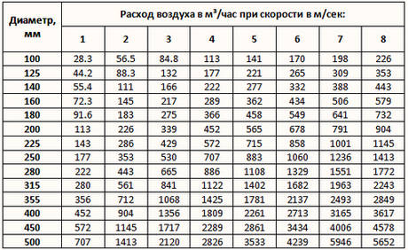
This table allows you to choose the cross section of the duct for duct ventilation, taking into account the volume and speed of movement of air masses
In addition, there are specialized calculation programs with which you can perform such calculations. For apartments and residential buildings, such programs can be even more convenient, since they give a more accurate result.
Heater
Calculation of the heater for the P1 system:
Heat consumption for air heating, W:
,(4.1)
where L is the air flow through the heater, m3/h;
— outside air density, kg/m3; =kg/m3;
tn= оС; (according to parameters B in the cold period);
tTo оС is the supply air temperature;
cp \u003d 1.2 - heat capacity of air, kJ / kg K;
Tue
Determine the required open area, m2, of the air-heating installation by air:
(4.2)
where is the same as in formula (4.1);
- mass air velocity (it is recommended to take within 6-10 kg / m2.s.
m2.
According to passport data /7/, the number and number (installed in parallel along the air flow) of heaters are selected, in which the total value of free air cross sections f, m2, is approximately equal to the required fґ.
At the same time, the heating surface area F, m2, and the area of the free section of the tubes of heaters for the passage of water (along the coolant) ftr.
According to fґ= 2.0 m2, according to table 4.17 /7/, we select a KVS-P type heater, No. 12 with technical characteristics:
f \u003d 1.2985 m2 - area of \u200b\u200bthe open section in air.
F = 108 m2 - heating surface area.
ftr \u003d 0.00347 m2 - area of \u200b\u200bliving section for the coolant.
Specify the mass air velocity:
(4.3)
where is the same as in formula (4.1);
?f is the free air section of the air heater, m2.
kg/m2 s.
Find the mass flow rate of water, kg / h:
(4.4)
where Q is the same as in formula (4.1);
cv is the specific heat capacity of water, taken equal to cv = 4.19 kJ/(kg.оС);
tG, tO — temperature of the water at the inlet and outlet of the heater, °C (according to the task).
tG,=150 °C;
tO \u003d 70 ° C;
kg/h;
We choose the layout and piping of the heaters and determine the speed of the water in the tubes of the heaters:
, (4.5)
where Gv — the same as in formula (4.4);
n is the number of parallel coolant flows passing through the calorific unit; n= 2;
ftr - living section of the air heater for water, m2;
u=
Calculate the required heating surface area of the calorific unit, m2
,(4.6)
where is the heat transfer coefficient, W / (m2. °C), the values of which can be determined by the formulas:
— for air heater KVS-P
,(4.7)
where is the same as in formula (4.2); u is the same as in formula (4.5);
W/m2oS.
— average temperature difference , °C, determined by the formula:
, (4.8)
where tG, tO — the same as in formula (4.4);
tn, tTo is the same as in formula (4.1).
OS.
m2.
Compare Ftr with the heating surface area of one heater F and determine the number of heaters installed in series along the air flow:
, (4.9)
Where F is the heating surface area of one heater, m2.
PC.
Find the stock of the heating surface area of the calorific unit:
, (4.10)
where n is the accepted number of heaters.
Determine the aerodynamic resistance of the air heater DP, Pa.
(4.11)
where is aerodynamic resistance, Pa:
DrPa,
The calculation results are shown in table 6
Table 6 - Calculation of the heating surface area and selection of the calorific unit
|
Heat consumption for air heating Q, W |
Required open area f, m2 |
Type and number of heater |
Number of heaters installed in parallel in the air, n |
Cross-sectional area for air passage of one air heater fzh, m2 |
The area of the open section of the calorific unit f=fzh*n, m2 |
Live section area of tubes of one air heater ftr, m2 |
Number of heaters connected in parallel on water, m |
Heating surface area of one heater F, m2 |
Heating surface area of the installation Ff=F*n` |
|
1 |
2 |
3 |
4 |
5 |
6 |
7 |
8 |
9 |
10 |
|
1345288,4 |
2,0 |
KVS12 |
2 |
1,2985 |
2,597 |
0,00347 |
2 |
108 |
324 |
|
The number of air heaters installed in series by air n` |
Actual mass air velocity Vс, kg/m2 0С |
Mass flow rate of water Gw, kg/h |
Water velocity in heater tubes u, m/s |
Heat transfer coefficient K, W/(m20С) |
Required unit heating surface area Ftr, m2 |
Heating surface area margin w, % |
Aerodynamic resistance of the installation DRD, Pa |
|
11 |
12 |
13 |
14 |
15 |
16 |
17 |
18 |
|
3 |
7,7 |
14333,5 |
0,57 |
37,2 |
320 |
1,3 |
60,1 |