2. Overlap welding
5.2.1.
Place for overlapping with leading
construction of crossings and horizontal
rotation angles (see Section 2.1) should be
choose on straight lines.
5.2.2.
Pits should be torn off along the way
trenching with precise anchoring
to the place of overlap.
Dimensions
pit must be at least shown
in fig. 5.2.1.
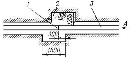
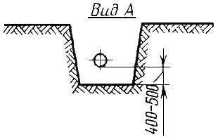
Rice.
5.2.1. The location of the pit when welding
overlap:
1
- overlap joint; 2 - pit in the trench; 3
— pipeline
Gap
backfilling of the pipeline must ensure
free installation of the overlap. At the same time, in
the trench must be left unfilled
one of the adjacent sections of the pipeline
at a distance of 60-80 m from the planned
lap joints.
5.2.3.
Advance Planning Practice
overlaps in places necessary
technological gaps (see section
2.1) must ensure the implementation of overlaps
without lagging behind the linear flow.
5.2.4.
Preferred type of installation
technological overlap is
option when both ends of the pipeline
free (not covered with earth) and located
in a trench (or on its "edge").
V
depending on specific conditions
construction can also be applied
option when one end of the pipeline
pinched (buried or connected, e.g.
with a crane node), and the other has a free
movement.
5.2.5.
In cases where it is provided
full or unilateral free
pipeline movement, closing
pipeline should be carried out
welding of one circumferential butt-overlap
(Fig. 5.2.2, diagram a).
Rice.
5.2.2. Two overlap welding schemes:
a
- overlap welding without load;
b
– overlap welding with load
V
if both ends are pinched
(Fig. 5.2.2, scheme b), there is a need
coil welding with two
ring joints.
5.2.6.
Assembly of elements of different thickness with
installation of overlaps is not allowed.
5.2.7.
When installing overlaps, it is prohibited:
—
pull the joined pipes;
—
force them to bend
mechanisms;
—
heat the pipe outside the area of direct
installation of a lap joint.
5.2.8.
When performing an overlap in conditions
free movement of the pipeline
(Fig. 5.2.2, scheme a) work is necessary
carry out in the following sequence:
—
one end of the pipeline
prepare for welding and lay on
supports 50-60 cm high along the axis of the pipeline;
—
whip forming another section
pipeline, hang out next to the first
and mark the place of the cut only
using a unified template;
—
make cutting and forming cutting
using a unified edger
cars;
—
in the process of docking, lift
cut lash by pipelayers on
height no more than 1 m at a distance of 60-80 m
from the end; elastic sagging of the circumcised
end allows you to combine one end
with another;
—
it is not allowed to rafter the pipe for
lifting at the location of the ring
welds.
5.2.9.
When performing an overlap in conditions
pinching of the ends of the pipeline (Fig.
5.2.2, scheme b) work must be carried out
in the following sequence:
—
cut the ends of the connected pipes and
prepare for welding according to
with the general requirements of clause 4.2.8;
—
make a coil from a pipe with the same
actual wall thickness, the same
diameter and the same strength class,
as the connected pipes; coil width
must be at least the diameter of the connected
pipes; equality of coil wall thicknesses
and the connected pipe must be registered
using an ultrasonic thickness gauge;
—
docked with the help of a pipelayer
coil to the pipeline, expose
required clearance (see paragraph 2.4.4) and produce
welding;
—
assembly of the second joint begins to produce
after the completion of the first joint.
5.2.10.
Interruptions in the process of welding overlaps
not allowed: overlap must be welded
in one go, from start to finish.
5.2.11.
Offset of edges in the ceiling part from
"5 o'clock" to "7 o'clock" should
be no more than 1 mm, on the rest
perimeter, according to the general regulation,
no more than 3 mm.
5.2.12.
Gap measured after
performance of tacks, should be
2.5±0.5 mm regardless of wall thickness
pipes. If the build process fails
maintain the minimum clearance
(actual gap was less than 2
mm), this section must be propylene
abrasive wheel 2.5 mm thick.
1. Butt welding of elements of different thicknesses
5.1.1.
For direct welding (without
adapters and tubular inserts
intermediate thickness) joints,
the thickness difference of which exceeds
the requirements of clause 2.4.1 of this Instruction,
must be done in advance
special edge preparation from the inside
and (or) outside of a thicker wall
element with wall thickness t to the thickness of the welded end t,
which should not exceed 1.5 times the thickness
less thick-walled element t (see Fig. 5 SP).
V
as a result of the condition of direct
connection is the value of "new"
thickness t.
In this case, t t.
t.
By
the value of t determines such technological
parameters like need and magnitude:
—
preheating;
—
local post-weld thermal
processing (see section 6).
V
if there are no special requirements
factory temperature
heating should be at the end thickness
faucet or fitting:
—
28 mm or less
………………………………………………… 150 °C
—
over 28 mm
……………………………………………………. 200 °С
5.1.2.
The joints of welded joints according to clause 5.1.1 must
be welded from the inside around the entire perimeter
with the provision of geometric parameters,
regulated by clause 2.6.10.4.
5.1.3.
Welding of elements of different thicknesses should
carried out in one session without interruption.
5.1.4.
If the "skirt" of reinforcement does not have
factory welded pipe,
corresponding to the size and steel grade
welded pipe, and its composition is different
on the chemical composition of the welded
pipes towards higher alloying
(nickel, aluminium, chromium,
manganese more than 2%, etc.), then in this case
selection of special materials required
and special technology as recommended
Customer.
V
In this case, the welding conditions are drawn up
an act that states:
—
reinforcement number;
—
steel grade, chemical composition of the “skirt”
and its strength properties;
—
thickness t of the end to be welded;
—
preheating conditions and
(if necessary) post-weld
heat treatment;
—
fill sequence diagram
cutting;
—
marks of welders;
—
radiographic findings (and
ultrasonic) control.
Example
technological map for welding
connecting parts is given in appendix.
6.
Why Use Preheat
The following are the main reasons for using preheat in a welding procedure.
- Heat treatment of welded structures eliminates surface moisture, and, consequently, helps to reduce cracking.
- It improves the subsequent melting and deposition of the weld metal.
- This reduces stress development by promoting uniform expansion and contraction between the weld and base metal.
- One of the main tasks of preheating is to slow down the cooling rate, which ensures uniform solidification of the joint. Thus, the microstructure of the metal will have high-quality mechanical properties.
Types
Based on application considerations, the heat treatment of welded structures can be determined in various ways.
- Preheating - the minimum temperature of the weld is set immediately before the start of welding.In the Welding Process Specification (WPS), it can be specified within a certain range.
- Preheat between passes - in multi-pass welding, the maximum temperature is required before the next pass begins. The heating in such a case cannot be lower than the minimum pre-heat treatment value.
- Welding temperature maintenance is the minimum temperature of the welding zone that must be maintained throughout the entire welding process. When work is interrupted, the temperature of the weld zone must not decrease.
Where is heat treatment of welded structures used?
As a rule, preheating is applied on the base metal at a certain distance from the weld. Let's assume that A is a certain part of the fillet weld, then there are two problems when calculating the distance for applying preheat.
- If the thickness of the base metal is less than or equal to 50 mm, then the value of A should not exceed 50 mm from the weld.
- If the thickness of the base metal exceeds 50 mm, then A must be less than 75 mm from the weld (instruction for issuing certificates to personnel checking the quality of welding: CSWIP 23.4).
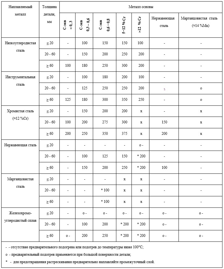
Preheat temperatures
Many will have a question: to what temperature values \u200b\u200bheat the metal? The recommended heating temperature of steel metal structures before welding will help answer this question. In the table below, it is displayed relative to the thickness and composition of different steels.
Equipment
Several types of equipment have been developed on the market today and are used in some commercial industries for the purpose of indicating, measuring and controlling the preheat temperature. The main temperature sensors and measuring devices that are used for this are listed below.
Contact thermometer - used to accurately measure temperature up to 350 degrees Celsius. It consists of a temperature-sensing device known as a "thermistor", its resistance decreases significantly when heated, and therefore is inversely proportional to temperature. However, in order to get accurate results, there is a need for "periodic calibration", which is a minus of this equipment.
Thermal pencil and thermal paste - consist of a material that melts or changes color when heated, depending on the temperature. They are affordable, low cost, and easy to use. Their weakness is that they do not give accurate measurements.
Thermocouple - works on the principle of measuring the thermoelectric potential difference between the hot weld metal and the weld metal to calculate the temperature. It is used during welding, after it and for heat treatment in order to constantly monitor and control the temperature of heating and cooling. The equipment gives accurate measurements over a wide range of temperatures, but it has the need for periodic calibration. This is a significant problem.
GESNm 12-11-002-08
Concomitant heating of welded pipe joints, outer diameter: 76 mm
LOCAL RESOURCE STATEMENT GESNm 12-11-002-08
| Name | unit of measurement |
| Concomitant heating of welded pipe joints, outer diameter: 76 mm | 1 joint |
| Scope of work | |
| Not provided |
PRICE VALUES
The price lists the direct costs of the work for the period March 2014 for the city of Moscow, which are calculated on the basis of standards 2014 with additions 1 by applying indexes to the prices of the resources used. Indices applied to federal prices 2000.
The following indexes and hourly rates from the "Union of Estimators" were used:
Index to the cost of materials: 7,485
Index to the cost of cars: 11,643
Used hourly rates:
In parentheses are the wages per month at a given hourly rate.
Hourly rate of the 1st category: 130.23 rubles. at one o'clock (22 920) rub. per month.
Hourly rate 2 categories: 141.21 rubles. at one o'clock (24 853) rub. per month.
Hourly rate 3 categories: 154.46 rubles. at one o'clock (27 185) rub. per month.
Hourly rate 4 categories: 174.34 rubles. at one o'clock (30 684) rub. per month.
Hourly rate of the 5th category: 200.84 rubles. at one o'clock (35 348) rub. per month.
Hourly rate of the 6th category: 233.96 rubles. at one o'clock (41 177) rub. per month.
By clicking on this link, you can see this standard calculated in 2000 prices.
The basis for the use of the composition and consumption of materials, machines and labor costs are GESN-2001
LABOR
| № | Name | Unit Change | Labor costs |
| 1 | Labor costs of assembly workers Category 4 | man-hour | 0,61 |
| 2 | Labor costs of machinists (for reference, included in the cost of EM) | man-hour | 0,25 |
| Total labor costs of workers | man-hour | 0,61 | |
| Wages of workers = 0.61 x 174.34 | Rub. | 106,35 | |
| Salary of machinists = 73.06 (for calculating invoices and profits) | Rub. | 73,06 |
Work schedule. Automatic construction according to the estimate.
OPERATION OF MACHINES AND MECHANISMS
| № | Cipher | Name | Unit Change | Consumption | St-st unit Rub. | TotalRUB. |
| 1 | 021102 | Truck-mounted cranes when working on the installation of process equipment 10 t | mash.-h | 0,25 | 1567,73 | 391,93 |
| 2 | 040502 | Manual Arc Welding Machines (DC) | mash.-h | 0,04 | 94,31 | 3,77 |
| 3 | 400001 | Cars onboard, carrying capacity up to 5 tons | mash.-h | 0,25 | 1014,92 | 253,73 |
| Total | Rub. | 649,43 |
CONSUMPTION OF MATERIALS
| № | Cipher | Name | Unit Change | Consumption | St-st unit Rub. | TotalRUB. |
| 1 | 411-0041 | Electricity | kWh | 0,65 | 2,99 | 1,94 |
| 2 | 501-0005 | Power cables for a voltage of 1000 V with copper conductors in a lead sheath of the SBGU brand, with the number of conductors - 3 and a cross section of 50 mm2 | 1000 m | 0,00001 | 1082745,07 | 10,83 |
| 3 | 502-0472 | Power flexible wires for voltage up to 380 V with insulation made of fiberglass and delta-asbestos impregnated with silicone varnish brand PSU-180, cross section 6 mm2 | 1000 m | 0,00005 | 104642,62 | 5,23 |
| 4 | 507-2833 | Mats high-temperature brand MVT-20 | m | 0,05 | 66,62 | 3,33 |
| 5 | 509-0963 | Asbestos fabric with glass fiber AST-1 1.8 mm thick | T | 0,00006 | 500447,1 | 30,03 |
| 6 | 509-0987 | Cord asbestos general purpose brand SHAON with a diameter of 2.0-2.5 mm | T | 0,00004 | 204340,5 | 8,17 |
| 7 | 999-9950 | Auxiliary non-standardized material resources (2% of the wages of workers) | rub. | 0,12 | 0,00 | |
| Total | Rub. | 59,53 |
TOTAL RESOURCES: RUB 708.97
TOTAL PRICE: RUB 815.32
You can see this standard calculated in 2000 prices. by following this link
The price was compiled according to the standards of GESN-2001 edition 2014 with additions 1 in prices March 2014.To determine the intermediate and final values of the price, the DefSmeta program was used
Estimate for the construction of a house, for the repair and decoration of apartments - the program DefSmeta
Program rentalThe program provides an assistant who will turn the budgeting into a game.