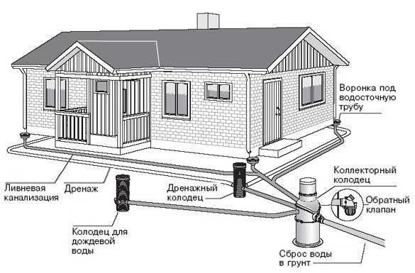
Types of drainage systems for underground structures
The following types of drainage systems can be used to divert water from underground structures.
1. Wall mounted
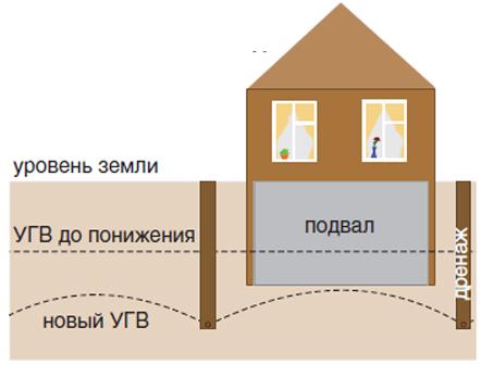
Melt and rainwater can accumulate in the surface layer of the soil if there is a natural or artificial aquiclude at a certain depth (a layer that does not allow water to penetrate deep into the soil). Such an aquiclude can be the upper plane of an underground structure. The waters that accumulate above the aquiclude in such cases are called perched water. For their removal, wall drainage is used. It is a system of buried drains (trenches covered with sand and gravel, inside which drainage pipes are laid). Drains encircle the structure and are connected to the main drainage system or to wells.
2. Plast
It is a layer of drainage material. It is located under an underground structure throughout its entire area. It is used to lower the groundwater level if the structure is built on an aquifer. It is connected by outgoing drains to the main drainage system.
3. Ring
It can provide a significant decrease in the level of groundwater around the protected object or in a selected area. Drains are arranged in such a way as to create a closed loop through which groundwater moves to the point of discharge. Annular drainage is arranged at a considerable distance from the protected structure in order to avoid displacement or subsidence of soils.
4. Internal
If there is a risk of water entering the underground room, internal drainage is arranged on its floor. It is a system of grooves protected from above by gratings. These grooves collect water from the floor of the room. Then it is diverted to the main drainage system or to a discharge point.
Mos-drainage engineers recommend that the following requirements be taken into account when arranging the drainage of underground structures.
- In the absence of conditions in which groundwater is removed from the drained area by gravity, it is necessary to use pumps to direct the flow.
- The use of the drainage system is possible only on the condition that the arrangement of the drainage will not entail negative consequences (washout of the soil, its displacement, etc.).
- If drainage is necessary, but there is a risk of negative consequences of the use of the drainage system, a number of preventive measures should be applied during its arrangement to strengthen the soil and prevent their erosion.
- Drainage is effective only in combination with other methods of waterproofing: the arrangement of blind areas and storm sewers, as well as the use of waterproofing.
The specific drainage system is selected in accordance with the characteristics of the soil in the territory, as well as with the features of the underground structure. For example, to protect the foundation in a site with a low level of groundwater, for prevention purposes, wall drainage is used to protect the structure from perched water. If we are talking about the construction of a tunnel or an underground room in an area with a high level of groundwater and a mixed soil composition, it is advisable to use a complex of drainage systems, which may include surface and ring type surface drainage, as well as internal drainage to prevent emergency flooding.
Drainage project example
Drainage project
Calculation and design
In order for the drainage, equipped on the land plot, to function correctly, to have the necessary throughput, before starting work, it is necessary to draw up a draft of the drainage system.
This is technical documentation, which is compiled taking into account generally accepted requirements and norms of SNiP.
The design begins with hydraulic drainage calculations.They will help determine the amount of material required for the work, as well as its characteristics.
In the course of calculations, you need to determine:
- the degree of permeability of all rocks that make up the soil on the site, as well as the tendency of hard rocks available in this area to crack;
- indicators of resistance of rocks to leaching of mineral particles, which can provoke soil salinization;
- the presence of tectonic disturbances on the site, the quality of the rocks on it;
- the average amount of precipitation falling in a given climatic zone for a certain period of time;
- the level and composition of groundwater at the site;
- features of the location and activity of groundwater sources.
Of course, if we are talking about a private area, then the drainage project in such cases is not always done, usually the standard system scheme is taken as the basis.
WALL DRAINAGE
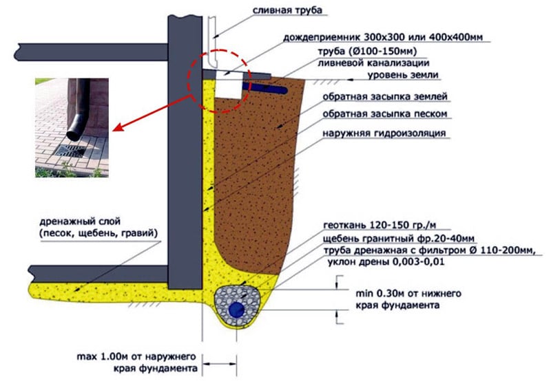
Wall drainage of the foundation is done in order to protect the base of the house from excess moisture that has formed naturally. This includes excess moisture from rain, melt and underground runoff increasing in spring and autumn. Such a device is able to protect the base of the structure from significant changes associated with the appearance of dampness and mold.
How wall drainage works
Wall drainage is designed to drain water, prevent interseasonal rise of groundwater and protect the building from damage.
Wall drainage is designed not only to drain groundwater, melt and rainwater from the foundation, it is also guaranteed to prevent the interseasonal rise of groundwater and protects the building from damage caused by increased humidity. If the wall drainage device is done correctly, then basements and cellars are not threatened by moisture accumulation, mold formation, etc.
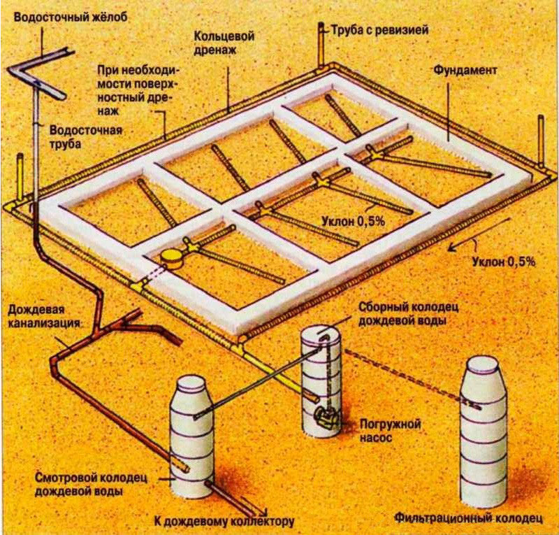
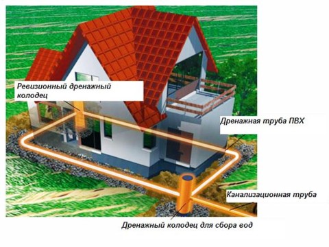
Wall drainage is a closed system of pipes, mounted in such a way that they are sloped, and the entire system is positioned below the point of the deepest base of the foundation. At the corners of the system, inspection manholes are placed, thanks to which it is possible to periodically break through the resulting blockages. Drainage pipes are laid around the perimeter of the house in special trenches and encircle the entire house. The water accumulated in the drainage pipes laid in rubble flows to the lowest point of the system - a collection well and is subsequently discharged by various available methods outside the site into a storm sewer or a nearby reservoir.
Wall drainage removes the mechanical and hydrostatic component of groundwater pressure exerted on the foundation. But drainage pipes do not completely eliminate the possibility of moisture penetration to the walls of cellars and basements, therefore, in order to prevent the penetration of capillary moisture into reinforced concrete devices placed below the ground level, and complete isolation from moisture, high-quality waterproofing is used.
Why is drainage called wall drainage? This binding is made according to the location of its components: both the aboveground and underground networks are located along the perimeter of the house, in close proximity to it, both in the depths of the soil and next to the basement. It includes:
A system of pipes laid underground; Vertical risers and wells; Ground ditches and drains.
To protect the foundations from the action of moisture, a whole range of solutions is used. The main ones are waterproofing and drainage systems. Both that, and another is a necessary condition of effective removal of water from the base.
Drainage systems are equipped for all types of foundations. They are designed individually, so as to take into account both the design features of the building and the characteristics of groundwater and soil on the site.
A quality foundation drainage system protects against:
wetting, moistening, destruction by water; formation of areas of mold, icing, frost; flooding of basement floors, cellars, cellars; moistening the walls and floor of the basement and first floor of the building;
Prices for wall drainage of the turnkey foundation.
the perimeter of the foundation is completely excavated to the width of the former foundation pit
the depth of the drainage system is done to the depth of the foundation
the drainage pipe is located along the foundation slab
operability of the drainage system all year round
drainage pipe HDPE D 110-160 mm wrapped with geotextile
the perimeter of the foundation is completely excavated to the width of the former foundation pit
the depth of the drainage system is done to the depth of the foundation
the drainage pipe is located along the foundation slab
Types of drainage systems protection of buildings on the site
The types of drainage systems installed around the house differ:
Mounting depth.
Way of organizing lines.
Destiny.
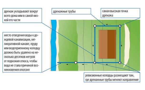
There are drainage networks that must be installed, regardless of the composition of the soil, the amount of moisture and climatic conditions. Annular drainage around the house is done in moisture-saturated loose soils and in areas located on slopes.
Comprehensive foundation protection
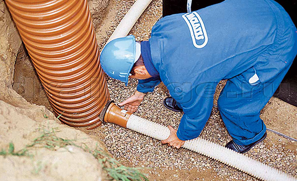
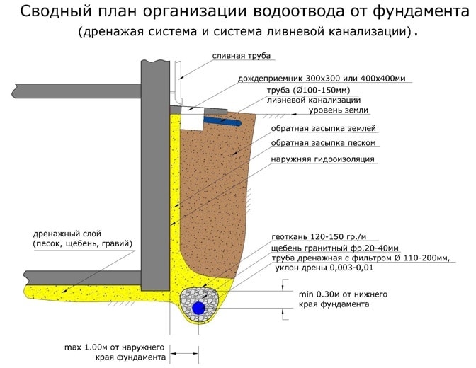
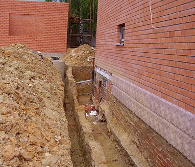
The main purpose of arranging drains in the near-wall space is to remove moisture from the outer surfaces of the dug-in foundation. The lines are formed at a minimum distance from the bottom of the foundation, deepening the trenches 30–50 cm below the edge of the base.
Drainage line in the wall space
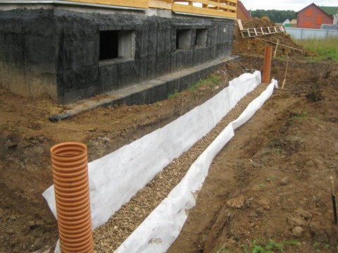
The wall drainage system is installed immediately after the completion of the construction of the foundation, before the foundation pit is backfilled. The drains are installed with observance of the slope from the highest point to the connection point of the ring in the drainage well.
Network device diagram
Drainage of the closed type. At the top point, a revision is installed for maintenance and flushing of lines. Inspection tanks are equipped in the corners where the drain bypasses the corner of the house. The drain is discharged into a drainage well.
Installation goals:
Removal of excess moisture from the walls and the lower foundation slab.
Protection of the structure from groundwater penetration.
Be sure to equip the surface system in areas not equipped with storm sewers. The surface protection system of the house, like the ring drainage, is built as a vicious circle with a slope. In the surface drainage network, point water collectors are separately installed in places where linear drains cannot cope with a large amount of water.
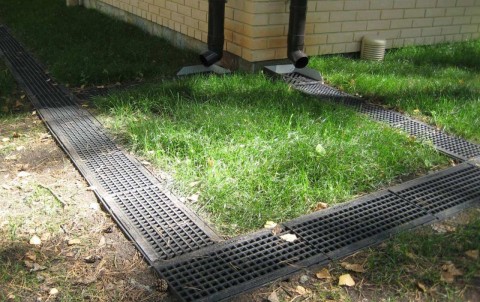
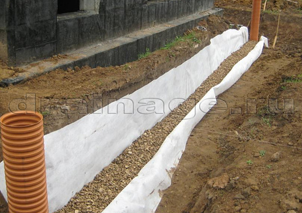
Surface drainage
Point water collectors with a drain to a drainage well are installed under downpipes, in recesses with difficult natural outflow. A closed network of surface open lines is created around the foundation.
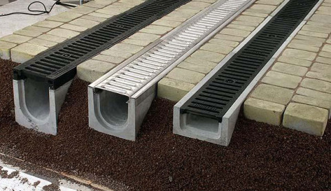
Trays with protective grids
Drainage trays are installed along the perimeter of the foundation, at a distance of up to 1 m from the wall, at a shallow depth. It is advisable to carry out the installation simultaneously with the arrangement of the blind area. Ready-made trays made of polymer or concrete with gratings made of plastic, cast iron or steel are laid in the prepared trenches.
The main task of installing an annular foundation drainage is to regulate (reduce) the water level inside the rock. Closed system. Installation is carried out at a distance from the house and deepened below a constant level of groundwater.
The purpose of the installation is to reduce the water level in the rock
The system is a closed ring or a semicircle if only a certain part of the site requires drainage. The ring network can be planned to protect a country house, several nearby buildings, part of a plot with a house.
Scheme of the device of the closed ring drainage of the foundation of the building
Trenches must be equipped below the base by at least 1 m, and below the freezing point of the soil. The distance from the walls should not be less than 5 m. The optimal distance is 5 - 8 m. To service the system, inspection manholes are installed at the turning points.
The choice of the optimal scheme depends on several factors:
Climatic conditions and rainfall.
Site relief.
Soil saturation with moisture and its composition.
Comprehensive foundation and house protection plan
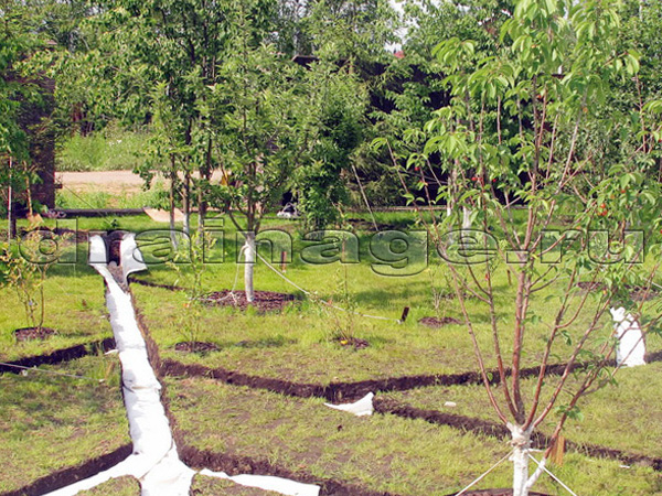
It is advisable to install surface drainage in areas where it is planned to lay paving slabs and stone. The network of trays will remove moisture, protect the decorative material from damage. Separate surface lines are arranged in the area for planting trees and sowing lawn grass. Wall drainage of the foundation is a mandatory element. Installing a simple system will protect the house from flooding, and the foundation from destruction and cracking.
It is mandatory to install an annular drainage on the site:
In complex water-saturated soils, with a predominance of sandy rocks.
With a constantly high level of groundwater.
If the foundation of the house is very deep (below the groundwater level).
When the house is built on a slope.
What to Consider When Designing Drainage
Design work, which includes the development of a scheme and the calculation of the drainage of the site, is carried out taking into account the state of the soil and climatic conditions in the area.
Each soil has a certain percentage of moisture content, the value of which depends on the carrying capacity of the upper layers of the soil and the depth of the aquifers. In this regard, there are three categories:
- Dry. Due to the good water permeability of the upper soil layers, a stable surface runoff is ensured. Groundwater is at a sufficient depth and does not have a special effect on the level of humidity.
- Raw. The upper layers have low water permeability, so water slowly leaves the surface. At the same time, groundwater does not moisten the upper layer of the soil. Such soils have signs of surface waterlogging, which are especially evident in the spring and autumn periods.
- Wet. Given the low permeability of the soil and the proximity of the aquifer, water in such an area can be retained on the surface for more than 20 days. Wet places include peaty and gleyed soils, as well as solonchaks.
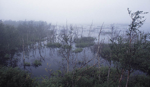
peat area
Another indicator for the correct calculation of the drainage of the site is the source of water supply. That is, the designer needs to find out how the soil is saturated with water.
- Atmospheric nutrition - showers and melt water. It is a source of waterlogging of a site with a small slope, where clay rock predominates.
- Ground feeding - capillary rise of moisture from the lower soil layers.
- Ground pressure supply - the influx of pressure water from the nearest aquifer.
- Abyssal nutrition is the thawing of ice crystals in the spring that have accumulated in the ground during frosts.

Heaving soil is especially dangerous for construction projects
Wall drainage calculation
Wall drainage is calculated per linear meter, and depends on the depth of the basement. The options are usually landscaping companies. offer two, the so-called standard and improved standard. Both the first and the second include digging a trench, laying a pipe, backfilling the bottom layer with crushed granite fraction 20-40 or sand, then laying a layer of coarse sand in geotextile, arranging a clay castle if necessary, compacting with soil and final testing. They differ in that in the first case, the backfilling of the pipe and the entire drain is done with sand, and in the second, the layer-by-layer backfilling is done first with granite rubble, and then with sand. The width in both design options is calculated from the depth of the drainage trench.
We will always welcome your call. Call us at tel. +7 741-16-55 and we will advise you on all your questions!
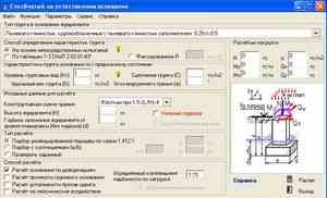
Design order
-
-
-
We define
drainage range according to the formula
I.P. Kusakina
-
-
R
= 2S
(3.17)
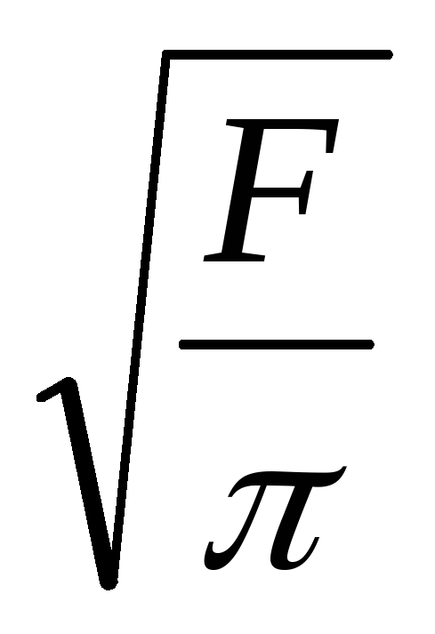
2. According to the formula
xO
=
 (3.18)
determine
circle radius xO,
equal area of a rectangle
F
= a ∙ b,
(3.19)
where
a
and b– parties
rectangle equal in area.
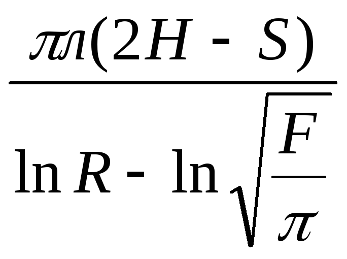
3. According to the formula
Q=
 (3.20)
determine
preliminary consumption of the annular
drainage Qprv.
4. Using the formula
gripping ability definitions
well
gzkv
=
 ,
,
(3.21)
where
gzkv
- gripping ability of the well;
Vq
= 65 m/day,
(3.22)
compose
two inequalities forn
-2 wells:
qzkvn
> Qprv
(3.23)
and
qzkv(n
–2) Qprv
. (3.24)
So,
forn
wells
gzkv
= 2 ,
,
(3.25)
where
atP
=
 , (3.26)
a
for n-2
wells
gzkv
= 2 ,
,
(3.27)
where
atn-2
=
 .
.
(3.28)
ring radius
wondering.
From
inequalities (3.23) and (3.24) by selection we determine
an even number of wells and distribute
them along the contour of the site.
5.
According to the site plan, we determine the distance
from the center A
to each well
X1,
X2,
…, Xn.
According to the formula
(3.20) determine the corrected water flow
ring drainage Q.
6. Next, count
groundwater levels by group
wells located in the same
conditions.
So,
for well 6, symmetrically located
with wells 1, 4, 9, make up a diagram and
calculate the distances from well 6 to
other wells: X1,
X2,
…, Xn.
At
this X6
= r.
Using formula (3.29), we determine at6:
at6
=
 (3.29)
In a similar way
determine the groundwater levels of all
wells and draw up schemes of depression
curves.
If necessary
lowering of the groundwater level by
site is not reached, then change
number of wells and their location.
2.
Payment
annular vertical drainage
For downgrading
groundwater level on the site
location of one of the workshops of the plant
circular drainage designed
vertical type, consisting of a row
tubular wells located along
direct contour of the protected structure
size 40x60 m.
site elevation
an average of 131.5m. Aquiclude mark (clay
Jurassic age) 177.5 m. Above the clays lie
alluvial coarse sands,
covered from the surface with a layer of loam
1–2 m thick. Filtration coefficient
sands 20 m/day. Groundwater is deposited
at around 130m, i.e. about 1.5m lower
the surface of the earth.
In order not to
there was flooding of buried basements
premises, the groundwater level should
be lowered to approximately 125m.
Accept
well radius r
\u003d 0.1 m, the magnitude of the decrease in the water level in
center of the site
S
= 130 - 125 = 5m.
Value
aquifer E
= 130m - 117.5m = 12.5m.
Order
calculation
next:
2.1.
Determine the radius of the drainage by
formula (3.17)
R
= 2S
m.
2.2. water depth in
ground in the center of action of wells
we get
ata
= H —
S = 12.5 m - 5 m =
7.5 m
2.3. circle radius,
equal to the protected area, will be
equals
XO
= m.
m.
2.4.
Preliminary consumption of the annular
drainage is determined by the formula (3.20)
Qprv
=
 m3/day
2.5.
Using formula (9.5), which defines
gripping ability of the well,
calculate the number of wells n,
using these two inequalities
qzkan
>Qright
and qzkv(n-2)
right
or
2
> 3,14 ∙0,1∙ Vg
∙atP
n
> 3600 and 2∙ 3.14∙ 0.1∙Vgatn-2(n-2)
At
this Vg
= 60 =
=
125.8 m/day
Asking
number of wells n
= 10. Then by formula (3.26)
at10
=
 m.
m.
According to the formula
y8
=
 m.
m.
Checking
accepted number of wells n
= 10 by two inequalities
2
∙3.14∙0.1∙ 126.8 ∙5∙10 = 4000 m3/day
> 3600 m3/day
2
∙3.14∙ 0.1 ∙126.8∙ 4.5 ∙8 = 2900 m3/day
3/day
We distribute
these wells along the contour of the shop.
2.6.
We calculate the corrected water consumption
by formula (3.20).
For
we calculate this according to the plan of the workshop
distance from its center A
to individual wells
X1
= X4
= X6
= X9
= 36m;
X5
= X10
= 30m;
X1
= X3
= X7
= X8
= 22m.
Then
Q
=
 m3/day
2.7. Counting
groundwater levels by group
wells located in the same
conditions.
So,
for well 6 (symmetrically located
with wells 1, 4 and 9) draw up a diagram and
calculate the distance from well 6 to
other wells (Fig. 9v):
X1,
X2
…..X10.
At
this X6
= r.
Then by formula (3.29) we obtain
y6
=
 6,3
6,3
m.
9.2.8. Checking
gripping capacity of the well
gzkv
= 2∙3,14 ∙0,1
∙126.8∙ 6.3 = 540 m3/day
> 390 m3/day,
where
390 =
 = average well flow.
2.9. Let's calculate
groundwater levels by well group
2, 3, 7, 8. Using the same method, we determine
at7
= 5.85m.
On wells 5 and 10
we get
at5
= 9.95m.
2.10. We build longitudinal
profiles for equal sections of wells and
check the necessary reduction
groundwater at the site. If this
reduction is not reached, then change
number of wells and their location.
Features of the arrangement of drainage in areas with a slope
Mos-drainage specialists believe that in areas with a slope of no more than 8 °, drainage is arranged in the same way as in areas with normal relief. If the slope is more than 8 °, the arrangement is carried out taking into account special requirements.
Sloping areas are characterized by a heterogeneous structure of the soil. If in one part of the territory groundwater is deep, then in another it can come close to the surface. At the same time, geological surveys are carried out. They provide information about the structure of soils and the location of the aquifer. These data are necessary when designing drainage.
The purpose of the drainage system on a site with a slope is to effectively drain the area. To do this, it is necessary to solve the following tasks:
lowering the level of groundwater throughout the territory to the required value (below the depth of freezing, deepening of the foundation and root systems of plants on the site);
safe collection and removal of surface moisture during rains and snowmelt
It is important that the water does not flow all over the site, washing out the soil. Instead, it is directed to the storm sewer, organizing the flow through the gutters and drains;
drainage of water from the bottom of the plot
So that moisture does not accumulate in the lower part of the territory, it is collected in a collector well, diverted to the nearest water intake. Another option is the arrangement of an artificial reservoir to collect moisture or the collection of water for use in irrigation.
To solve these problems, complex work is carried out: using buried open or closed drainage, storm sewers, and local facilities for collecting water. Specific solutions are selected individually: according to the characteristics of the site, the level of soil moisture, the requirements for drainage of the territory, the estimated cost of work on the arrangement of the drainage system.
When is drainage used?
All drainage systems according to their function can be divided into several types:
- Wall drainage is designed to drain groundwater from the building and protect the site
- The drainage of the wetland area is carried out by more complex systems, which include a number of technological measures.
wall drainage
The need to use one or another type can be determined by a number of indirect signs.
You need drainage if:
- In the spring there is a regular flooding of the basement. In this case, the organization of drainage should be carried out in conjunction with the improvement of the waterproofing of the foundation.
The rising water level in drinking wells also testifies to the close location of groundwater.
The swampy state of the site speaks for itself.
At high humidity, there is also a large number of water-loving plants.
Calculation of the main drainage parameters
Having designed the circuit, it is necessary to calculate the main parameters, such as:
- pipe diameter;
- geotextile density;
- trench depth;
- drain slope;
- distance between inspection wells.
To accurately calculate the diameter of the drainage pipe, you should know the required intensity of drainage. In practice, pipes Ø100-110 mm are most often used, which have a throughput of 7 l / s. This is quite enough to cope with heavy rainfall and perched water.
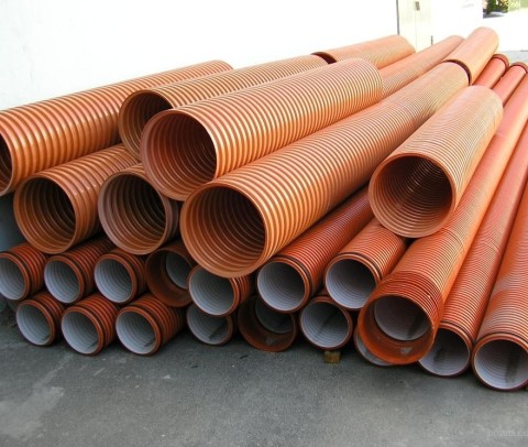
Drainage pipes of different diameters
The geotextile fabric acts as a filter that protects the drain from clogging. The main indicator of this material is the density
It is the calculation of the density of geotextiles for drainage that experts pay special attention to.If this characteristic is low, the fabric may tear during installation
On the other hand, excessive density reduces the moisture filtration coefficient. For drainage work, the value of 100-150 g / m² is considered the best indicator.
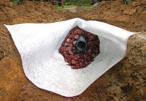
Geotextile fabric is an important element of drainage
The depth of laying drainage pipes is influenced by two factors - the depth of soil freezing and the depth of the foundation (for wall drainage).
If the drain freezes in winter, then during the melting of snow it will not be able to remove excess moisture, and the efficiency of the system will tend to zero. To prevent this, the trench must be developed taking into account the climatic features of a particular area.
The calculation of the depth of wall drainage is very simple: 30 cm is added to the lowest point of the foundation. This will be enough to intercept groundwater during the rainy season or during floods.
Wall drainage scheme
The correct slope of the drainage pipes is of great importance for the functionality of the system. The absence of a slope will lead to stagnation of water, and too large an angle will contribute to the appearance of deposits in the internal cavity of the pipeline.
The depth of the water collector is calculated as follows. First, the distance from the top point of the drainage to the receiving well is measured, then the resulting sum is divided by 100. For example, the length of the drainage pipeline is 30 m, then the collector should be located 30 cm below the top point of the system.
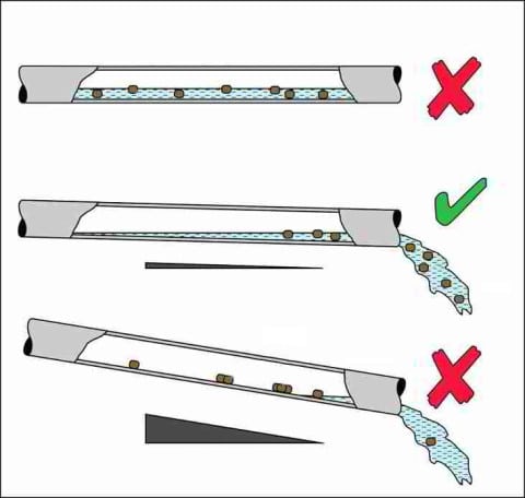
Drain laying angle
The location of revision wells is standardized by SNiP. According to the approved rules, points for maintenance and cleaning of drainage should be located at all turns of the pipeline. For straight sections that are long, wells are installed every 35 m.
Revision wells perform the function of monitoring the performance of the drainage system
This article provides general data for calculating drainage. However, it should be borne in mind that any drainage system is unique in its own way. Therefore, in order for the drainage on the site to work as efficiently as possible, design and installation issues must be resolved by specialists.